EP0647998A1 - Schaltfeld mit Kühlkanal zwischen Hauptstromkreisen und Hilfsstromkreisen - Google Patents
Schaltfeld mit Kühlkanal zwischen Hauptstromkreisen und Hilfsstromkreisen Download PDFInfo
- Publication number
- EP0647998A1 EP0647998A1 EP94250206A EP94250206A EP0647998A1 EP 0647998 A1 EP0647998 A1 EP 0647998A1 EP 94250206 A EP94250206 A EP 94250206A EP 94250206 A EP94250206 A EP 94250206A EP 0647998 A1 EP0647998 A1 EP 0647998A1
- Authority
- EP
- European Patent Office
- Prior art keywords
- control panel
- air duct
- fan
- device unit
- panel according
- Prior art date
- Legal status (The legal status is an assumption and is not a legal conclusion. Google has not performed a legal analysis and makes no representation as to the accuracy of the status listed.)
- Granted
Links
- 238000001816 cooling Methods 0.000 title claims description 18
- 238000010438 heat treatment Methods 0.000 abstract description 4
- 238000009434 installation Methods 0.000 abstract description 2
- 230000000694 effects Effects 0.000 description 6
- 230000000712 assembly Effects 0.000 description 3
- 238000000429 assembly Methods 0.000 description 3
- 238000005259 measurement Methods 0.000 description 1
- 230000005855 radiation Effects 0.000 description 1
Images


Classifications
-
- H—ELECTRICITY
- H02—GENERATION; CONVERSION OR DISTRIBUTION OF ELECTRIC POWER
- H02B—BOARDS, SUBSTATIONS OR SWITCHING ARRANGEMENTS FOR THE SUPPLY OR DISTRIBUTION OF ELECTRIC POWER
- H02B1/00—Frameworks, boards, panels, desks, casings; Details of substations or switching arrangements
- H02B1/56—Cooling; Ventilation
- H02B1/565—Cooling; Ventilation for cabinets
Definitions
- the invention relates to a switchgear panel of a switchgear assembly with at least one first device unit for main circuits and with at least one further device unit for auxiliary circuits, the further device unit being separated from the first device unit by walls.
- Switchgear panels of this type are known in switchgear for different areas of application, in particular for low-voltage switchgear and medium-voltage switchgear.
- the DE company publication Siemens shows: "Low-voltage switchgear 8PU. 003", order no. A19100-E74-A92, pages 4 and 5, a control panel of a low-voltage switchgear with a circuit breaker as a device unit for main circuits and a room above, which serves to accommodate a device unit for auxiliary circuits.
- This includes in particular control and display devices as well as terminal strips.
- a considerable amount of heat is emitted from the busbars arranged on the rear of the device unit for auxiliary circuits and the circuit breaker, which acts on the auxiliary power device unit and can disrupt its functions, in particular if it contains electronic components.
- the invention is based on the object of protecting the device unit for auxiliary circuits from excessive heating and therefore impairing its function.
- an additional wall for forming an air duct is arranged at a distance from the separating walls. Since there are now two walls at a distance from one another, heat radiation can have a less direct effect on the auxiliary power devices. A natural air flow can also form through the air duct, which prevents excessive heating of the auxiliary power devices. With a suitable dimensioning of the air duct, it is therefore possible to provide an operating temperature which is conducive to the auxiliary power unit in all operating conditions of the switchgear.
- the desired cooling effect can be favored in that the additional walls have approximately the area of the separating walls and that the air duct has approximately the width of the switch panel. Based on this dimensioning, the cooling effect can be influenced by the distance between the walls.
- the air duct can be formed by relatively simply shaped parts.
- the air duct can be designed to be approximately angularly shielding the underside and the rear of the second device unit.
- the air duct can have a first mouth located at the top of the control panel and a further mouth located at the front of the control panel.
- an embodiment of the invention is suitable in which in the area of the first, i.e. H. a fan is arranged on the top of the switch panel, the cooling air in the direction of the second, d. H. promotes muzzle located on the front of the panel. This direction of flow runs counter to the natural direction of flow and thus brings the upper wall areas most exposed to heat loss into contact with the cooler air from the area around the switchgear.
- the fan can be, for example, a commercially available cross-flow or roller fan operated by an electric motor, of which several will be briefly explained.
- a niche for receiving the fan can be provided on the upper side of the switch panel and the first opening of the air duct can adjoin the niche and opposite the top of the switch panel be set back.
- the fan can have its own housing, which can be mounted flush with the top of the switch panel or projecting above the top.
- the advantage is achieved that the fan is not located inside the switch panel and can therefore be replaced without stopping or switching off the switchgear. It is assumed that during the relatively short period of time, which requires the replacement of the fan, no inadmissible heating of the device unit for auxiliary circuits will occur, since there is still a certain, albeit reduced, cooling effect due to natural flow through the air duct.
- the air duct is set up for natural flow or for operation with a fan, it can be advantageous to provide at least one wall of the air duct with cooling fins in order to enlarge the surface.
- the air duct can be designed as a prefabricated assembly which can be mounted in the switch panel.
- a niche used to hold the fan can be included in the assembly, for example in such a way that the niche is flush with the top of the control panel or partially or completely overhangs the top.
- An embodiment of the invention is particularly suitable for switchgear assemblies which comprise a plurality of switch panels set up next to one another, in which the mouth located at the top of the switch panel corresponds to a feed channel which may be common to several switch panels, a fan being arranged at at least one end of the feed channel .
- the air requirement for cooling is high, it may be advisable to install a fan with half the total power required at both ends of the supply channel instead of a single fan designed for the entire requirement for cooling air. If, on the other hand, the aspect of operational safety is predominant, the two fans can each be dimensioned for the total output, one of the two fans being able to be activated by means of a closure slide assigned to the fans.
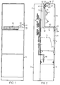
- FIG. 1 shows a control panel of a low-voltage switchgear from the front, while FIG. 2 shows the control panel schematically in section.
- Figures 3, 4 and 5 each show as a detail modified embodiments of an air duct and the type of installation of a fan in a schematically simplified representation.
- a switchgear consisting of several switch panels with a common supply duct for cooling air is shown in simplified perspective in FIG. 6.
- the control panel 1 has a rear busbar compartment 2 with busbars 3 (FIG. 2) and a device compartment 4 which contains a first device unit 5, designed as a circuit breaker, for main circuits. Above the equipment room 4 there is an auxiliary equipment room 6, which contains at least one second device unit 7 for auxiliary circuits. It can z. B. are electronic display, measurement and control devices that are relatively sensitive to heat. Beneath the equipment compartment 4 there is a cable connection compartment 8 in the control panel 1, into which cables can be connected to outlet rails 10 of the appliance unit 4 via a cable duct (not shown).
- the upper auxiliary equipment compartment 5 is thus exposed to the heat loss that is emitted from the busbars 3 and from the first equipment unit 5.
- a special wall arrangement protects the auxiliary equipment compartment 6 against excessive heat.
- further walls 13 and 14 are arranged parallel to walls 11 and 12, which delimit the auxiliary equipment compartment 6 at the rear or at the bottom thereof.
- an air duct 15 is formed, which has a first mouth 16 on the top 17 of the control panel 1 and a further mouth 20 on the front 21 of the control panel 1.
- the walls 11 and 12 and 13 and 14 extend in pairs parallel to one another over the entire width of the control panel 1. Accordingly, the angular air duct also has essentially the width of the control panel, as a result of which the auxiliary equipment compartment is moved rearwards and downwards is shielded. Air is drawn in by a fan 22 on the upper side 17 of the control panel 1 and is conveyed in the direction of the arrow 23 to the front opening 20 of the air duct 15, where an outlet grille 24 is attached. In this arrangement, a relatively small cross section of the air duct 15 with a correspondingly small distance between the walls 11 and 13 and 12 and 14 from one another is sufficient.
- the fan 22 After removal of a cover 25 provided on the upper side 17 of the control panel 1, the fan 22 is accessible in a recess 26 which is formed at the bottom by a support plate 27 mounted at an angle to the upper side 17 and delimiting the auxiliary equipment space 6. The fan 22 can therefore be replaced without opening the equipment compartment 4 or the auxiliary equipment compartment 6.
- the support plate 27 is an integral part of the control panel 1, while the air duct 15 is formed by a prefabricated assembly 30 which is subsequently inserted into the control panel 1.
- the assembly 30 is shown with a larger line width.
- FIG. 4 shows that the air duct 15 and the recess 26 are produced together as a prefabricated assembly 31. This can also include the fan 22.
- FIG. 5 shows that the air duct 15 and the recess 26 can be formed by separate assemblies 32 and 33, the assembly 32 reaching up to the top 17 of the control panel 1 and the assembly 33 being flush with the air duct 15 afterwards Top 17 is placed.
- the wall 13 of the assembly 33 is provided with cooling fins 34 in order to increase the cooling effect by increasing the surface. This measure can also be used irrespective of the inclusion of the wall 13 in the assembly 32 in all the other exemplary embodiments described and can also be used in the other walls that delimit the air duct 15.
- FIG. 6 schematically shows an exemplary embodiment which is particularly suitable for switchgear assemblies with a plurality of switch panels.
- a total of five switch panels 35 are set up side by side, which have a first mouth 37 on their top 36 and a second mouth 40 on their front 38.
- a supply duct 41 for cooling air extends over the upper sides 36 of all switch panels 35, which is shown broken off in the area of the central switch panel 35 in order to make one of the orifices 37 visible.
- an electric motor-operated fan 43 is arranged, which can be, for example, a radial fan. Depending on the dimensioning of these fans 43, cooling is carried out by one or both fans. For operational safety reasons, it may be advisable to provide one fan as a reserve.
Landscapes
- Engineering & Computer Science (AREA)
- Power Engineering (AREA)
- Patch Boards (AREA)
- Cooling Or The Like Of Electrical Apparatus (AREA)
- Containers, Films, And Cooling For Superconductive Devices (AREA)
Abstract
Description
- Die Erfindung betrifft ein Schaltfeld einer Schaltanlage mit wenigstens einer ersten Geräteeinheit für Hauptstromkreise und mit wenigstens einer weiteren Geräteeinheit für Hilfsstromkreise, wobei die weitere Geräteeinheit durch Wände gegenüber der ersten Geräteeinheit abgetrennt ist.
- Schaltfelder dieser Art sind bei Schaltanlagen für unterschiedliche Einsatzgebiete bekannt, insbesondere für Niederspannungs-Schaltanlagen und Mittelspannungs-Schaltanlagen. Beispielsweise zeigt die DE-Firmendruckschrift Siemens: "Niederspannungs-Schaltanlage 8PU. 003", Best.-Nr. A19100-E74-A92, Seiten 4 und 5 ein Schaltfeld einer Niederspannungs-Schaltanlage mit einem Leistungsschalter als Geräteeinheit für Hauptstromkreise und einem darüber befindlichen Raum, der zur Aufnahme einer Geräteeinheit für Hilfsstromkreise dient. Zu dieser gehören insbesondere Steuer- und Anzeigegeräte sowie Klemmleisten. Von den rückseitig der Geräteeinheit für Hilfsstromkreise angeordneten Sammelschienen und dem Leistungsschalter wird eine beträchtliche Wärmemenge abgegeben, welche die Hilfsstrom-Geräteeinheit beaufschlagt und deren Funktionen stören kann, insbesondere wenn darin elektronische Komponenten enthalten sind.
- Sinngemäße Verhältnisse bestehen bei einer Mittelspannungs-Schaltanlage, wie sie der DE-B-1 790 184 zu entnehmen ist. Auch hier besteht somit das Problem, daß die Geräteeinheit für Hilfsstromkreise einer erheblichen Wärmeeinwirkung ausgesetzt sein kann.
- Der Erfindung liegt ausgehend von einem Schaltfeld der eingangs genannten Art die Aufgabe zugrunde, die Geräteeinheit für Hilfsstromkreise vor einer zu starken und daher ihre Funktion beeinträchtigenden Erwärmung zu schützen.
- Die Aufgabe wird gemäß der Erfindung dadurch gelöst, daß im Abstand zu den abtrennenden Wänden jeweils eine zusätzliche Wand zur Bildung eines Luftkanals angeordnet ist. Da nunmehr zwei Wände im Abstand voneinander vorhanden sind, kann Wärmestrahlung weniger direkt auf die Hilfsstromgeräte einwirken. Auch kann sich durch den Luftkanal eine natürliche Luftströmung ausbilden, die eine übermäßige Erwärmung der Hilfsstromgeräte verhindert. Bei geeigneter Dimensionierung des Luftkanals ist es daher möglich, bei allen Betriebsbedingungen der Schaltalage für eine der Hilfsstrom-Geräteeinheit zuträgliche Betriebstemperatur zu sorgen.
- Die angestrebte Kühlwirkung kann dadurch begünstigt werden, daß die zusätzlichen Wände etwa die Fläche der abtrennenden Wände aufweisen und daß der Luftkanal etwa die Breite des Schaltfeldes besitzt. Ausgehend von dieser Bemessung kann die Kühlwirkung durch den Abstand der Wände beeinflußt werden.
- Der Luftkanal kann durch relativ einfach geformte Teile gebildet werden. Insbesondere bei einer Anordnung der ersten Geräteeinheit unterhalb der zweiten Geräteeinheit kann der Luftkanal etwa winkelförmig die Unterseite und die Rückseite der zweiten Geräteeinheit abschirmend ausgebildet sein.
- Um eine vollständige Durchströmung des Luftkanals und damit eine möglichst wirksame Kühlung zu erreichen, kann der Luftkanal eine erste, an der Oberseite des Schaltfeldes gelegene Mündung und eine weitere, an der Frontseite des Schaltfeldes gelegene Mündung besitzen.
- Wie bereits erwähnt, ist es bei geeigneter Dimensionierung des Luftkanals möglich, allein durch natürlichen Auftrieb erwärmter Luft für eine ausreichende Kühlwirkung zu sorgen. Es gibt jedoch Schaltanlagen, bei denen die spezifische Belastung so groß und/oder der für den Luftkanal zur Verfügung stehende Raum derart beschränkt ist, daß durch natürlichen Auftrieb keine ausreichende Kühlung zu erreichen ist. Für diese Fälle eignet sich eine Ausführungsform der Erfindung, bei der im Bereich der ersten, d. h. an der Oberseite des Schaltfeldes befindlichen Mündung ein Lüfter angeordnet ist, der Kühlluft in Richtung der zweiten, d. h. an der Frontseite des Schaltfeldes befindlichen Mündung fördert. Diese Strömungsrichtung verläuft entgegen der natürlichen Strömungsrichtung und bringt somit die obenliegenden, am stärksten durch Verlustwärme beaufschlagten Wandbereiche zuerst mit der kühleren Luft aus der Umgebung der Schaltanlage in Berührung.
- Für die Unterbringung des Lüfters, der beispielsweise ein handelsüblicher elektromotorisch betriebener Querstrom- oder Walzenlüfter sein kann, bestehen mehrere Möglichkeiten, von denen mehrere kurz erläutert werden sollen. Insbesondere kann an der Oberseite des Schaltfeldes eine Nische zur Aufnahme des Lüfters vorgesehen sein und die erste Mündung des Luftkanals kann an die Nische anschließend sowie gegenüber der Oberseite des Schaltfeldes zurückgesetzt angeordnet sein. Ferner kann der Lüfter ein eigenes Gehäuse aufweisen, das bündig mit der Oberseite des Schaltfeldes oder über die Oberseite überragend montierbar ist. In jedem Fall wird der Vorteil erzielt, daß sich der Lüfter nicht im Inneren des Schaltfeldes befindet und daher ohne Stillsetzung bzw. Abschaltung der Schaltanlage auswechselbar ist. Dabei wird davon ausgegangen, daß während der relativ kurzen Zeitspanne, die das Auswechseln des Lüfters erfordert, keine unzulässige Erwärmung der Geräteeinheit für Hilfsstromkreise eintreten wird, da noch eine gewisse, wenngleich verminderte, Kühlwirkung durch natürliche Durchströmung des Luftkanals besteht.
- Unabhängig davon, ob der Luftkanal für natürliche Durchströmung oder für den Betrieb mit einem Lüfter eingerichtet ist, kann es vorteilhaft sein, wenigstens eine Wand des Luftkanals zwecks Vergrößerung der Oberfläche mit Kühlrippen zu versehen.
- Der Luftkanal kann durch Verbindung der ihn begrenzenden Wände als vorgefertigte und in dem Schaltfeld montierbare Baugruppe ausgebildet sein. Dabei kann eine zur Aufnahme des Lüfters dienende Nische in die Baugruppe einbezogen sein, etwa so, daß die Nische mit der Oberseite des Schaltfeldes abschließt oder über die Oberseite ganz oder teilweise übersteht.
- Besonders für Schaltanlagen, die mehrere nebeneinander aufgestellte Schaltfelder umfaßt, eignet sich eine Ausführungsform der Erfindung, bei der die an der Oberseite des Schaltfeldes gelegene Mündung mit einem ggfs. für mehrere Schaltfelder gemeinsamen Zuführkanal korrespondiert, wobei an wenigstens einem Ende des Zuführkanals ein Lüfter angeordnet ist.
- Ist infolge der Anzahl von Schaltfeldern der Luftbedarf für die Kühlung groß, so kann es sich empfehlen, anstelle eines einzigen, für den gesamten Bedarf an Kühlluft bemessenen Lüfters an beiden Enden des Zuführkanals einen Lüfter mit der halben geforderten Gesamtleistung zu montieren. Ist dagegen der Gesichtspunkt der Betriebssicherheit überwiegend, so können die beiden Lüfter jeweils für die Gesamtleistung bemessen sein, wobei durch je einen den Lüftern zugeordneten Verschlußschieber wahlweise der eine oder der andere der beiden Lüfter wirksam zu machen ist.
- Die Erfindung wird im folgenden anhand der in den Figuren dargestellten Ausführungsbeispiele näher erläutert.
- Die Figur 1 zeigt ein Schaltfeld einer Niederspannungs-Schaltanlage von vorn, während die Figur 2 das Schaltfeld schematisch im Schnitt zeigt.
- Die Figuren 3, 4 und 5 zeigen jeweils als Einzelheit abgewandelte Ausführungsformen eines Luftkanals und der Einbauart eines Lüfters in schematisch vereinfachter Darstellung.
- Eine aus mehreren Schaltfeldern bestehende Schaltanlage mit einem gemeinsamen Zuführkanal für Kühlluft ist vereinfacht perspektivisch in der Figur 6 dargestellt.
- Das Schaltfeld 1 gemäß den Figuren 1 und 2 weist einen rückwärtigen Sammelschienenraum 2 mit Sammelschienen 3 (Figur 2) und einen Geräteraum 4 auf, der eine als Leistungsschalter ausgebildete erste Geräteeinheit 5 für Hauptstromkreise enthält. Oberhalb des Geräteraumes 4 befindet sich ein Hilfsgeräteraum 6, der wenigstens eine zweite Geräteeinheit 7 für Hilfsstromkreise enthält. Es kann sich dabei z. B. um elektronische Anzeige-, Meß- und Steuergeräte handeln, die relativ wärmeempfindlich sind. Unterhalb des Geräteraumes 4 befindet sich in dem Schaltfeld 1 ein Kabelanschlußraum 8, in den über einen nicht gezeigten Kabelkanal herangeführte Kabel mit Abgangsschienen 10 der Geräteeinheit 4 verbunden werden können.
- Der obere Hilfsgeräteraum 5 ist somit der Verlustwärme ausgesetzt, die von Sammelschienen 3 und von der ersten Geräteeinheit 5 abgegeben wird. Durch eine besondere Wandanordnung wird der Hilfsgeräteraum 6 gegen eine zu starke Wärmeeinwirkung geschützt. Hierzu sind parallel zu Wänden 11 und 12, welche den Hilfsgeräteraum 6 an dessen Rückseite bzw. nach unten begrenzen, weitere Wände 13 und 14 angeordnet. Hierdurch wird ein Luftkanal 15 gebildet, der eine erste Mündung 16 an der Oberseite 17 des Schaltfeldes 1 und eine weitere Mündung 20 an der Frontseite 21 des Schaltfeldes 1 besitzt.
- Wie die Figuren 1 und 2 zeigen, erstrecken sich die Wände 11 und 12 sowie 13 und 14 paarweise parallel zueinander über die gesamte Breite des Schaltfeldes 1. Dementsprechend hat auch der winkelförmige Luftkanal im wesentlichen die Breite des Schaltfeldes, wodurch der Hilfsgeräteraum nach hinten und unten abgeschirmt ist. Durch einen Lüfter 22 wird Luft an der Oberseite 17 des Schaltfeldes 1 angesaugt und in Richtung des Pfeiles 23 zur frontseitigen Mündung 20 des Luftkanals 15 gefördert, wo ein Austrittsgitter 24 angebracht ist. Es genügt bei dieser Anordnung ein verhältnismäßig geringer Querschnitt des Luftkanals 15 mit entsprechend kleinem Abstand der Wände 11 und 13 sowie 12 und 14 voneinander.
- Der Lüfter 22 ist nach Abnahme einer an der Oberseite 17 des Schaltfeldes 1 vorgesehenen Abdeckung 25 in einer Nische 26 zugänglich, die durch ein winklig zur Oberseite 17 montiertes und den Hilfsgeräteraum 6 begrenzendes Tragblech 27 nach unten gebildet ist. Daher kann der Lüfter 22 ausgewechselt werden, ohne den Geräteraum 4 oder den Hilfsgeräteraum 6 zu öffnen.
- In den Figuren 3, 4 und 5 ist nur der obere Bereich des Schaltfeldes gezeigt, um unterschiedliche Ausführungen des Luftkanals 15 zu veranschaulichen.
- In dem Beispiel gemäß der Figur 3 ist das Tragblech 27 fester Bestandteil des Schaltfeldes 1, während der Luftkanal 15 durch eine vorgefertigte Baugruppe 30 gebildet ist, die nachträglich in das Schaltfeld 1 eingefügt ist. Zur Hervorhebung ist die Baugruppe 30 mit größerer Strichstärke dargestellt. Das weitere Ausführungsbeispiel gemäß der Figur 4 läßt erkennen, daß der Luftkanal 15 und die Nische 26 gemeinsam als vorgefertigte Baugruppe 31 hergestellt sind. Diese kann auch den Lüfter 22 umfassen.
- Als weiteres Ausführungsbeispiel zeigt die Figur 5, daß der Luftkanal 15 und die Nische 26 durch gesonderte Baugruppen 32 und 33 gebildet sein können, wobei die Baugruppe 32 bis zur Oberseite 17 des Schaltfeldes 1 reicht und die Baugruppe 33 bündig an den Luftkanal 15 anschließend auf die Oberseite 17 aufgesetzt ist. Die Wand 13 der Baugruppe 33 ist mit Kühlrippen 34 versehen, um durch Vergrößerung der Oberfläche die Kühlwirkung zu steigern. Diese Maßnahme ist auch unabhängig von der Einbeziehung der Wand 13 in die Baugruppe 32 bei allen anderen beschriebenen Ausführungsbeispielen anwendbar und kann auch wahlweise bei den anderen Wänden getroffen werden, die den Luftkanal 15 begrenzen.
- In der Figur 6 ist schematisch ein besonders für Schaltanlagen mit mehreren Schaltfeldern geeignetes Ausführungsbeispiel gezeigt. Insgesamt sind fünf Schaltfelder 35 nebeneinander aufgestellt, die an ihrer Oberseite 36 eine erste Mündung 37 und an ihrer Frontseite 38 eine zweite Mündung 40 besitzen. Über die Oberseiten 36 aller Schaltfelder 35 erstreckt sich ein Zuführkanal 41 für Kühlluft, der im Bereich des mittleren Schaltfeldes 35 abgebrochen gezeigt ist, um eine der Mündungen 37 sichtbar zu machen. An beiden Enden 42 des Zuführkanals 41 ist je ein elektromotorisch betriebener Lüfter 43 angeordnet, der beispielsweise ein Radiallüfter sein kann. Je nach der Bemessung dieser Lüfter 43 erfolgt die Kühlung durch einen oder beide Lüfter. Aus Gründen der Betriebssicherheit kann es sich empfehlen, jeweils einen Lüfter als Reserve vorzusehen. Durch einen Verschlußschieber 44 an jedem Ende des Zuführkanals 41 ist es dann möglich, die Gesamtanlage durch den linken oder den rechten Lüfter 43 zu kühlen. Im Schadensfall kann der betreffende Lüfter bei geschlossenem Verschlußschieber 44 ausgewechselt werden, ohne die Schaltanlage stillsetzen zu müssen.
Claims (11)
- Schaltfeld (1) einer Schaltanlage mit wenigstens einer ersten, für Hauptstromkreise vorgesehenen Geräteeinheit (5) und mit wenigstens einer weiteren, für Hilfsstromkreise vorgesehenen Geräteeinheit (7), wobei die weitere Geräteeinheit (7) durch Wände (11, 12) gegenüber der ersten Geräteeinheit (5) angetrennt ist,
dadurch gekennzeichnet, daß im Abstand zu den abtrennenden Wänden (11, 12) jeweils eine zusätzliche Wand (13, 14) zur Bildung eines Luftkanals (15) angeordnet ist. - Schaltfeld nach Anspruch 1,
dadurch gekennzeichnet, daß die zusätzlichen Wände (13, 14) etwa die Fläche der abtrennenden Wände (11, 12) aufweisen und daß der Luftkanal (15) etwa die Breite des Schaltfeldes (1) besitzt. - Schaltfeld nach Anspruch 1 oder 2,
dadurch gekennzeichnet, daß bei einer Anordnung der ersten Geräteeinheit (5) unterhalb der zweiten Geräteeinheit (7) der Luftkanal (15) etwa winkelförmig die Unterseite und die Rückseite der zweiten Geräteeinheit (7) abschirmend ausgebildet ist. - Schaltfeld nach Anspruch 3,
dadurch gekennzeichnet, daß der Luftkanal (15) eine erste, an der Oberseite (17) des Schaltfeldes (1) gelegene Mündung (16) und eine weitere, an der Frontseite (21) des Schaltfeldes (1) gelegene Mündung (20) besitzt. - Schaltfeld nach Anspruch 4,
dadurch gekennzeichnet, daß im Bereich der ersten Mündung (16) ein Lüfter (22) angeordnet ist, der Kühlluft in Richtung (23) der zweiten Mündung (20) fördert. - Schaltfeld nach Anspruch 5,
dadurch gekennzeichnet, daß an der Oberseite (17) des Schaltfeldes (1) eine Nische (26) zur Aufnahme des Lüfters (22) vorgesehen ist und daß die erste Mündung (16) des Luftkanals (15) an die Nische (26) anschließend sowie gegenüber der Oberseite (17) des Schaltfeldes (1) zurückgesetzt angeordnet ist. - Schaltfeld nach einem der vorangehenden Ansprüche,
dadurch gekennzeichnet, daß wenigstens eine Wand (13) des Luftkanals (15) mit Kühlrippen (34) versehen ist. - Schaltfeld nach einem der vorangehenden Ansprüche,
dadurch gekennzeichnet, daß der Luftkanal (15) durch Verbindung der ihn begrenzenden Wände (11, 12, 13, 14) als vorgefertige und in dem Schaltfeld (1) montierbare Baugruppe (30, 31, 32) ausgebildet ist. - Schaltfeld nach Anspruch 8,
dadurch gekennzeichnet, daß eine zur Aufnahme eines Lüfters (22) dienende Nische (26) in die Baugruppe (31) einbezogen ist. - Schaltfeld nach Anspruch 5,
dadurch gekennzeichnet, daß die an der Oberseite (36) des Schaltfeldes (35) gelegene Mündung (37) mit einem für ggfs. mehrere nebeneinander aufgestellte Schaltfelder (35) gemeinsamen Zuführkanal (41) korrespondiert und daß an wenigstens einem Ende des Zuführkanals (41) ein Lüfter (43) angeordnet ist. - Schaltfeld nach Anspruch 10,
dadurch gekennzeichnet, daß an beiden Enden (42) des Zuführkanals (41) ein Lüfter (43) angeordnet ist und daß durch je einen den Lüftern (43) zugeordneten Verschlußschieber (44) wahlweise der eine oder der andere der beiden Lüfter (43) wirksam zu machen ist.
Applications Claiming Priority (2)
| Application Number | Priority Date | Filing Date | Title |
|---|---|---|---|
| DE4330509A DE4330509A1 (de) | 1993-09-03 | 1993-09-03 | Schaltfeld mit je einer Geräteeinheit für Hauptstromkreise und Hilfsstromkreise |
| DE4330509 | 1993-09-03 |
Publications (2)
| Publication Number | Publication Date |
|---|---|
| EP0647998A1 true EP0647998A1 (de) | 1995-04-12 |
| EP0647998B1 EP0647998B1 (de) | 1997-05-14 |
Family
ID=6497235
Family Applications (1)
| Application Number | Title | Priority Date | Filing Date |
|---|---|---|---|
| EP94250206A Revoked EP0647998B1 (de) | 1993-09-03 | 1994-08-22 | Schaltfeld mit Kühlkanal zwischen Hauptstromkreisen und Hilfsstromkreisen |
Country Status (4)
| Country | Link |
|---|---|
| EP (1) | EP0647998B1 (de) |
| AT (1) | ATE153185T1 (de) |
| DE (2) | DE4330509A1 (de) |
| GR (1) | GR3024446T3 (de) |
Cited By (1)
| Publication number | Priority date | Publication date | Assignee | Title |
|---|---|---|---|---|
| CN104600960A (zh) * | 2014-04-17 | 2015-05-06 | 南车株洲电力机车研究所有限公司 | 紧凑型电源柜主单元柜及其组装方法及柜内组件排布方法 |
Families Citing this family (2)
| Publication number | Priority date | Publication date | Assignee | Title |
|---|---|---|---|---|
| DE202005018284U1 (de) * | 2005-04-08 | 2006-02-02 | Rittal Gmbh & Co. Kg | Kühleinheit |
| DE102005037802A1 (de) * | 2005-08-03 | 2007-02-08 | Siemens Ag | Schaltfeld mit Luftleitelement |
Citations (5)
| Publication number | Priority date | Publication date | Assignee | Title |
|---|---|---|---|---|
| DE1062307B (de) * | 1953-08-06 | 1959-07-30 | Siemens Ag | Aus Ober- und Unterteil bestehendes Schaltpult |
| JPS5476939A (en) * | 1977-12-02 | 1979-06-20 | Toshiba Corp | Enclosed switchboard |
| FR2610471A1 (fr) * | 1987-02-03 | 1988-08-05 | Chantereine Sarl Ateliers | Armoire de protection pour dispositif de redresseur de courant |
| DE8915141U1 (de) * | 1989-12-23 | 1990-02-08 | Calor-Emag Elektrizitäts AG, 4030 Ratingen | Gekapseltes Schaltfeld |
| WO1991006995A1 (en) * | 1989-10-26 | 1991-05-16 | Abb Sace S.P.A. | Gas-insulated electric switchboard |
Family Cites Families (2)
| Publication number | Priority date | Publication date | Assignee | Title |
|---|---|---|---|---|
| DE8611936U1 (de) * | 1986-04-30 | 1990-07-05 | Stewing, Albert, 4270 Dorsten | Kabelverzweigerschrank |
| CH681404A5 (de) * | 1991-01-10 | 1993-03-15 | Sprecher Energie Ag |
-
1993
- 1993-09-03 DE DE4330509A patent/DE4330509A1/de not_active Withdrawn
-
1994
- 1994-08-22 DE DE59402734T patent/DE59402734D1/de not_active Revoked
- 1994-08-22 AT AT94250206T patent/ATE153185T1/de active
- 1994-08-22 EP EP94250206A patent/EP0647998B1/de not_active Revoked
-
1997
- 1997-08-13 GR GR970402089T patent/GR3024446T3/el unknown
Patent Citations (5)
| Publication number | Priority date | Publication date | Assignee | Title |
|---|---|---|---|---|
| DE1062307B (de) * | 1953-08-06 | 1959-07-30 | Siemens Ag | Aus Ober- und Unterteil bestehendes Schaltpult |
| JPS5476939A (en) * | 1977-12-02 | 1979-06-20 | Toshiba Corp | Enclosed switchboard |
| FR2610471A1 (fr) * | 1987-02-03 | 1988-08-05 | Chantereine Sarl Ateliers | Armoire de protection pour dispositif de redresseur de courant |
| WO1991006995A1 (en) * | 1989-10-26 | 1991-05-16 | Abb Sace S.P.A. | Gas-insulated electric switchboard |
| DE8915141U1 (de) * | 1989-12-23 | 1990-02-08 | Calor-Emag Elektrizitäts AG, 4030 Ratingen | Gekapseltes Schaltfeld |
Non-Patent Citations (2)
| Title |
|---|
| HANS DEDERICHS: "Kompaktschalthäuser für Antriebsspeisungen und Anlagen-Leitsystem in Walzwerken", BBC NACNRICHTEN, vol. 66, no. 7, 1984, MANNHEIM, pages 243 - 249 * |
| PATENT ABSTRACTS OF JAPAN vol. 3, no. 98 (E - 131) 18 August 1979 (1979-08-18) * |
Cited By (2)
| Publication number | Priority date | Publication date | Assignee | Title |
|---|---|---|---|---|
| CN104600960A (zh) * | 2014-04-17 | 2015-05-06 | 南车株洲电力机车研究所有限公司 | 紧凑型电源柜主单元柜及其组装方法及柜内组件排布方法 |
| CN104600960B (zh) * | 2014-04-17 | 2017-02-15 | 南车株洲电力机车研究所有限公司 | 紧凑型电源柜主单元柜及其组装方法及柜内组件排布方法 |
Also Published As
| Publication number | Publication date |
|---|---|
| GR3024446T3 (en) | 1997-11-28 |
| DE59402734D1 (de) | 1997-06-19 |
| EP0647998B1 (de) | 1997-05-14 |
| ATE153185T1 (de) | 1997-05-15 |
| DE4330509A1 (de) | 1995-03-09 |
Similar Documents
| Publication | Publication Date | Title |
|---|---|---|
| EP0297308A2 (de) | Schaltschrank | |
| EP0872000B1 (de) | Schienenkanalsystem einer niederspannungs-schaltanlage | |
| EP1579747A1 (de) | Messgerätmodule und messgerät | |
| DE69209443T2 (de) | Schaltfeld | |
| DE3337313A1 (de) | Hochfrequenz-heizgeraet | |
| EP0647998B1 (de) | Schaltfeld mit Kühlkanal zwischen Hauptstromkreisen und Hilfsstromkreisen | |
| DE19928400C2 (de) | Berührungssichere elektrische Hochspannungsversorgung | |
| EP0458832B1 (de) | Gerätesystem mit einem ersten und wenigstens einem daran ankuppelbaren zweiten elektrischen gerät | |
| DE69702063T2 (de) | Modulare schrankanordnung zur steuerung elektrischer geräte, insbesondere für motoren | |
| EP0253758B1 (de) | Elektrische Schaltanlage in schlagwettergeschützter Ausführung mit einer Steckvorrichtung | |
| DE19852713C1 (de) | Leistungsschalter | |
| EP0008138A1 (de) | Kühlvorrichtung für gekapselte Schaltfelder | |
| DE29505243U1 (de) | Erdungsvorrichtung für einen Einschub eines Energieverteilerschrankes | |
| EP0872002B1 (de) | Niederspannungs-schaltanlage zur abgabe oder verteilung elektrischer energie | |
| EP2362506B1 (de) | Lichtbogenbegrenzungsvorrichtung | |
| DE29517962U1 (de) | Einrichtung zur Regelung der Temperatur für Schalt- und Verteilerschränke | |
| EP0621668A1 (de) | Berührungsschutz für Stromverteilschienen | |
| DE9202810U1 (de) | Generator-Leistungsschalter für eine horizontale Generatorableitung | |
| EP1070372B1 (de) | Bedienfeld eines mit geräteeinschüben bestückten niederspannungs-schaltfeldes | |
| EP1232509B1 (de) | Niederspannungs-leistungsschalter mit einem eine vorderwand und eine rückwand aufweisenden gehäuse | |
| DE29805235U1 (de) | Schaltschrank | |
| EP0560067B1 (de) | Gehäusesystem | |
| DE202025103009U1 (de) | Stromsammelschrank und Energiespeichersystem | |
| EP1524741B1 (de) | Niederspannungsschaltanlage | |
| DE3438206A1 (de) | Anordnung zur waermeableitung bei geraeteeinsaetzen der nachrichtentechnik |
Legal Events
| Date | Code | Title | Description |
|---|---|---|---|
| PUAI | Public reference made under article 153(3) epc to a published international application that has entered the european phase |
Free format text: ORIGINAL CODE: 0009012 |
|
| AK | Designated contracting states |
Kind code of ref document: A1 Designated state(s): AT BE CH DE DK ES FR GB GR IE IT LI LU MC NL PT SE |
|
| 17P | Request for examination filed |
Effective date: 19951011 |
|
| GRAG | Despatch of communication of intention to grant |
Free format text: ORIGINAL CODE: EPIDOS AGRA |
|
| GRAH | Despatch of communication of intention to grant a patent |
Free format text: ORIGINAL CODE: EPIDOS IGRA |
|
| 17Q | First examination report despatched |
Effective date: 19961029 |
|
| GRAH | Despatch of communication of intention to grant a patent |
Free format text: ORIGINAL CODE: EPIDOS IGRA |
|
| GRAA | (expected) grant |
Free format text: ORIGINAL CODE: 0009210 |
|
| AK | Designated contracting states |
Kind code of ref document: B1 Designated state(s): AT BE CH DE DK ES FR GB GR IE IT LI LU MC NL PT SE |
|
| REF | Corresponds to: |
Ref document number: 153185 Country of ref document: AT Date of ref document: 19970515 Kind code of ref document: T |
|
| REG | Reference to a national code |
Ref country code: CH Ref legal event code: EP |
|
| REF | Corresponds to: |
Ref document number: 59402734 Country of ref document: DE Date of ref document: 19970619 |
|
| PGFP | Annual fee paid to national office [announced via postgrant information from national office to epo] |
Ref country code: AT Payment date: 19970723 Year of fee payment: 4 |
|
| PG25 | Lapsed in a contracting state [announced via postgrant information from national office to epo] |
Ref country code: SE Effective date: 19970814 |
|
| PGFP | Annual fee paid to national office [announced via postgrant information from national office to epo] |
Ref country code: MC Payment date: 19970814 Year of fee payment: 4 Ref country code: IE Payment date: 19970814 Year of fee payment: 4 |
|
| REG | Reference to a national code |
Ref country code: CH Ref legal event code: NV Representative=s name: SIEMENS SCHWEIZ AG |
|
| PG25 | Lapsed in a contracting state [announced via postgrant information from national office to epo] |
Ref country code: ES Free format text: LAPSE BECAUSE OF FAILURE TO SUBMIT A TRANSLATION OF THE DESCRIPTION OR TO PAY THE FEE WITHIN THE PRESCRIBED TIME-LIMIT Effective date: 19970816 |
|
| PGFP | Annual fee paid to national office [announced via postgrant information from national office to epo] |
Ref country code: SE Payment date: 19970821 Year of fee payment: 4 |
|
| PGFP | Annual fee paid to national office [announced via postgrant information from national office to epo] |
Ref country code: PT Payment date: 19970822 Year of fee payment: 4 Ref country code: BE Payment date: 19970822 Year of fee payment: 4 |
|
| PGFP | Annual fee paid to national office [announced via postgrant information from national office to epo] |
Ref country code: DK Payment date: 19970826 Year of fee payment: 4 |
|
| PGFP | Annual fee paid to national office [announced via postgrant information from national office to epo] |
Ref country code: FR Payment date: 19970827 Year of fee payment: 4 |
|
| PGFP | Annual fee paid to national office [announced via postgrant information from national office to epo] |
Ref country code: GR Payment date: 19970829 Year of fee payment: 4 Ref country code: ES Payment date: 19970829 Year of fee payment: 4 |
|
| PGFP | Annual fee paid to national office [announced via postgrant information from national office to epo] |
Ref country code: LU Payment date: 19970902 Year of fee payment: 4 |
|
| GBT | Gb: translation of ep patent filed (gb section 77(6)(a)/1977) |
Effective date: 19970811 |
|
| ET | Fr: translation filed | ||
| PGFP | Annual fee paid to national office [announced via postgrant information from national office to epo] |
Ref country code: DE Payment date: 19971022 Year of fee payment: 4 |
|
| REG | Reference to a national code |
Ref country code: GR Ref legal event code: FG4A Free format text: 3024446 |
|
| PGFP | Annual fee paid to national office [announced via postgrant information from national office to epo] |
Ref country code: CH Payment date: 19971119 Year of fee payment: 4 |
|
| REG | Reference to a national code |
Ref country code: PT Ref legal event code: SC4A Free format text: AVAILABILITY OF NATIONAL TRANSLATION Effective date: 19970813 |
|
| PLBQ | Unpublished change to opponent data |
Free format text: ORIGINAL CODE: EPIDOS OPPO |
|
| PLBI | Opposition filed |
Free format text: ORIGINAL CODE: 0009260 |
|
| 26 | Opposition filed |
Opponent name: AEG SACHSENWERK GMBH Effective date: 19980120 |
|
| PLBF | Reply of patent proprietor to notice(s) of opposition |
Free format text: ORIGINAL CODE: EPIDOS OBSO |
|
| NLR1 | Nl: opposition has been filed with the epo |
Opponent name: AEG SACHSENWERK GMBH |
|
| PLBF | Reply of patent proprietor to notice(s) of opposition |
Free format text: ORIGINAL CODE: EPIDOS OBSO |
|
| PG25 | Lapsed in a contracting state [announced via postgrant information from national office to epo] |
Ref country code: LU Free format text: LAPSE BECAUSE OF NON-PAYMENT OF DUE FEES Effective date: 19980822 Ref country code: IE Free format text: LAPSE BECAUSE OF NON-PAYMENT OF DUE FEES Effective date: 19980822 |
|
| RDAH | Patent revoked |
Free format text: ORIGINAL CODE: EPIDOS REVO |
|
| RDAG | Patent revoked |
Free format text: ORIGINAL CODE: 0009271 |
|
| STAA | Information on the status of an ep patent application or granted ep patent |
Free format text: STATUS: PATENT REVOKED |
|
| REG | Reference to a national code |
Ref country code: CH Ref legal event code: PL |
|
| 27W | Patent revoked |
Effective date: 19980918 |
|
| GBPR | Gb: patent revoked under art. 102 of the ep convention designating the uk as contracting state |
Free format text: 980918 |
|
| NLR2 | Nl: decision of opposition | ||
| REG | Reference to a national code |
Ref country code: PT Ref legal event code: MF4A Effective date: 19990204 |