EP0647998B1 - Tableau de distribution avec un canal de refroidissement entre les circuits principaux et les circuits auxiliaires - Google Patents
Tableau de distribution avec un canal de refroidissement entre les circuits principaux et les circuits auxiliaires Download PDFInfo
- Publication number
- EP0647998B1 EP0647998B1 EP94250206A EP94250206A EP0647998B1 EP 0647998 B1 EP0647998 B1 EP 0647998B1 EP 94250206 A EP94250206 A EP 94250206A EP 94250206 A EP94250206 A EP 94250206A EP 0647998 B1 EP0647998 B1 EP 0647998B1
- Authority
- EP
- European Patent Office
- Prior art keywords
- switchpanel
- air duct
- fan
- device unit
- walls
- Prior art date
- Legal status (The legal status is an assumption and is not a legal conclusion. Google has not performed a legal analysis and makes no representation as to the accuracy of the status listed.)
- Revoked
Links
- 238000001816 cooling Methods 0.000 title claims description 18
- 238000012216 screening Methods 0.000 claims 1
- 238000010438 heat treatment Methods 0.000 abstract description 4
- 238000009434 installation Methods 0.000 abstract description 2
- 230000000694 effects Effects 0.000 description 6
- 230000000712 assembly Effects 0.000 description 3
- 238000000429 assembly Methods 0.000 description 3
- 238000005259 measurement Methods 0.000 description 1
- 230000005855 radiation Effects 0.000 description 1
Images

Classifications
-
- H—ELECTRICITY
- H02—GENERATION; CONVERSION OR DISTRIBUTION OF ELECTRIC POWER
- H02B—BOARDS, SUBSTATIONS OR SWITCHING ARRANGEMENTS FOR THE SUPPLY OR DISTRIBUTION OF ELECTRIC POWER
- H02B1/00—Frameworks, boards, panels, desks, casings; Details of substations or switching arrangements
- H02B1/56—Cooling; Ventilation
- H02B1/565—Cooling; Ventilation for cabinets
Definitions
- the invention relates to a switchgear panel of a switchgear assembly with at least one first device unit for main circuits and with at least one further device unit for auxiliary circuits, the further device unit being separated from the first device unit by walls.
- Switchgear panels of this type are known in switchgear for different areas of application, in particular for low-voltage switchgear and medium-voltage switchgear.
- the DE company publication Siemens shows: "Low-voltage switchgear 8PU. 003", order no. A19100-E74-A92, pages 4 and 5, a control panel of a low-voltage switchgear with a circuit breaker as a device unit for main circuits and a room above, which serves to accommodate a device unit for auxiliary circuits.
- This includes in particular control and display devices as well as terminal strips.
- a considerable amount of heat is emitted from the busbars arranged on the rear of the device unit for auxiliary circuits and the circuit breaker, which acts on the auxiliary power device unit and can disrupt its functions, in particular if it contains electronic components.
- the invention is based on the object of protecting the device unit for auxiliary circuits from excessive heating and therefore impairing its function.
- an additional wall for forming an air duct is arranged at a distance from the separating walls. Since there are now two walls at a distance from one another, heat radiation can have a less direct effect on the auxiliary power devices. A natural air flow can also form through the air duct, which prevents excessive heating of the auxiliary power devices. With a suitable dimensioning of the air duct, it is therefore possible to provide an operating temperature which is conducive to the auxiliary power unit in all operating conditions of the switchgear.
- the desired cooling effect can be favored in that the additional walls have approximately the area of the separating walls and that the air duct has approximately the width of the switch panel. Based on this dimensioning, the cooling effect can be influenced by the distance between the walls.
- the air duct can be formed by relatively simply shaped parts.
- the air duct can be designed to be approximately angularly shielding the underside and the rear of the second device unit.
- the air duct can have a first mouth located at the top of the control panel and a further mouth located at the front of the control panel.
- an embodiment of the invention is suitable in which in the area of the first, i.e. H. a fan is arranged on the top of the switch panel, the cooling air in the direction of the second, d. H. promotes muzzle located on the front of the panel. This direction of flow runs counter to the natural direction of flow and thus brings the upper wall areas most exposed to heat loss into contact with the cooler air from the area around the switchgear.
- the fan can be, for example, a commercially available cross-flow or roller fan operated by an electric motor, of which several will be briefly explained.
- a niche for receiving the fan can be provided on the upper side of the switch panel and the first opening of the air duct can adjoin the niche and opposite the top of the switch panel be set back.
- the fan can have its own housing, which can be mounted flush with the top of the switch panel or projecting above the top.
- the advantage is achieved that the fan is not located inside the switch panel and can therefore be replaced without stopping or switching off the switchgear. It is assumed that during the relatively short period of time that requires replacement of the fan, there will be no inadmissible heating of the device unit for auxiliary circuits, since there is still a certain, albeit reduced, cooling effect due to natural flow through the air duct.
- the air duct is set up for natural flow or for operation with a fan, it can be advantageous to provide at least one wall of the air duct with cooling fins in order to enlarge the surface.
- the air duct can be designed as a prefabricated assembly which can be mounted in the switch panel.
- a niche used to hold the fan can be included in the assembly, for example in such a way that the niche is flush with the top of the control panel or partially or completely overhangs the top.
- An embodiment of the invention is particularly suitable for switchgear assemblies which comprise a plurality of switch panels set up next to one another, in which the mouth located at the top of the switch panel corresponds to a feed channel which may be common for several switch panels, with a fan being arranged at at least one end of the feed channel .
- the air requirement for cooling is high, it may be advisable to install a fan with half the total power required at both ends of the supply channel instead of a single fan designed for the entire requirement for cooling air. If, on the other hand, the aspect of operational safety is predominant, the two fans can each be dimensioned for the total output, one of the two fans being able to be activated by means of a closure slide assigned to the fans.
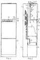
- FIG. 1 shows a control panel of a low-voltage switchgear from the front, while FIG. 2 shows the control panel schematically in section.
- Figures 3, 4 and 5 each show as a detail modified embodiments of an air duct and the type of installation of a fan in a schematically simplified representation.
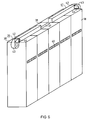
- a switchgear consisting of several switch panels with a common supply duct for cooling air is shown in simplified perspective in FIG. 6.
- the control panel 1 has a rear busbar compartment 2 with busbars 3 (FIG. 2) and a device compartment 4 which contains a first device unit 5, designed as a circuit breaker, for main circuits. Above the equipment room 4 there is an auxiliary equipment room 6, which contains at least one second device unit 7 for auxiliary circuits. It can z. B. are electronic display, measurement and control devices that are relatively sensitive to heat. Beneath the equipment compartment 4 there is a cable connection compartment 8 in the control panel 1, into which cables can be connected to outlet rails 10 of the appliance unit 4 via a cable duct (not shown).
- the upper auxiliary equipment compartment 5 is thus exposed to the heat loss that is emitted from the busbars 3 and from the first equipment unit 5.
- a special wall arrangement protects the auxiliary equipment compartment 6 against excessive heat.
- further walls 13 and 14 are arranged parallel to walls 11 and 12, which delimit the auxiliary equipment compartment 6 at the rear or at the bottom thereof.
- an air duct 15 is formed, which has a first mouth 16 on the top 17 of the control panel 1 and a further mouth 20 on the front 21 of the control panel 1.
- the walls 11 and 12 and 13 and 14 extend in pairs parallel to one another over the entire width of the control panel 1. Accordingly, the angular air duct also has essentially the width of the control panel, as a result of which the auxiliary equipment compartment is moved rearwards and downwards is shielded. Air is drawn in by a fan 22 on the upper side 17 of the control panel 1 and is conveyed in the direction of the arrow 23 to the front opening 20 of the air duct 15, where an outlet grille 24 is attached. In this arrangement, a relatively small cross section of the air duct 15 with a correspondingly small distance between the walls 11 and 13 and 12 and 14 from one another is sufficient.
- the fan 22 After removal of a cover 25 provided on the upper side 17 of the control panel 1, the fan 22 is accessible in a recess 26 which is formed at the bottom by a support plate 27 mounted at an angle to the upper side 17 and delimiting the auxiliary equipment space 6. The fan 22 can therefore be replaced without opening the equipment compartment 4 or the auxiliary equipment compartment 6.
- the support plate 27 is an integral part of the control panel 1, while the air duct 15 is formed by a prefabricated assembly 30 which is subsequently inserted into the control panel 1.
- the assembly 30 is shown with a larger line width.
- FIG. 4 shows that the air duct 15 and the recess 26 are produced together as a prefabricated assembly 31. This can also include the fan 22.
- FIG. 5 shows that the air duct 15 and the recess 26 can be formed by separate assemblies 32 and 33, the assembly 32 reaching up to the top 17 of the control panel 1 and the assembly 33 being flush with the air duct 15 afterwards Top 17 is placed.
- the wall 13 of the assembly 33 is provided with cooling fins 34 in order to increase the cooling effect by increasing the surface. This measure can also be used irrespective of the inclusion of the wall 13 in the assembly 32 in all the other exemplary embodiments described and can optionally also be used in the other walls that delimit the air duct 15.
- FIG. 6 schematically shows an embodiment which is particularly suitable for switchgear assemblies with a plurality of switchgear panels.
- a total of five switch panels 35 are set up side by side, which have a first mouth 37 on their top 36 and a second mouth 40 on their front 38.
- a supply duct 41 for cooling air extends over the upper sides 36 of all switch panels 35, which is shown broken off in the area of the central switch panel 35 in order to make one of the orifices 37 visible.
- an electric motor-operated fan 43 is arranged, which can be, for example, a radial fan. Depending on the dimensioning of these fans 43, cooling is carried out by one or both fans. For operational safety reasons, it may be advisable to provide one fan as a reserve.
Landscapes
- Engineering & Computer Science (AREA)
- Power Engineering (AREA)
- Patch Boards (AREA)
- Cooling Or The Like Of Electrical Apparatus (AREA)
- Containers, Films, And Cooling For Superconductive Devices (AREA)
Claims (11)
- Tableau de distribution (1) d'une installation de distribution, comportant au moins une première unité (5) d'appareils prévue pour des circuits électriques principaux, et au moins une autre unité (7) d'appareils destinée à des circuits électriques auxiliaires, l'autre unité (7) d'appareils étant séparée de la première unité (5) d'appareils par des cloisons (11, 12),
caractérisé par le fait qu'une cloison supplémentaire (13, 14), qui est destinée à former un canal d'aération (15), est disposée à une certaine distance des cloisons de séparation (11, 12). - Tableau de distribution selon la revendication 1,
caractérisé par le fait que les cloisons supplémentaires (13, 14) ont approximativement la même surface que les cloisons de séparation (11, 12), et que la largeur du canal d'aération (15) est approximativement égale à celle du tableau de distribution (1). - Tableau de distribution selon la revendication 1 ou 2,
caractérisé par le fait que, lorsque la première unité (5) d'appareils est disposée au-dessous de la deuxième unité (7) d'appareils, le canal d'aération (15) est réalisé avec une forme angulaire qui protège le côté inférieur et la face arrière de la deuxième unité (7) d'appareils. - Tableau de distribution selon la revendication 3,
caractérisé par le fait que le canal d'aération (15) comporte un premier orifice (16) situé du côté supérieur (17) du tableau de distribution (1), et un autre orifice (20) situé en face frontale (21) du tableau de distribution (1). - Tableau de distribution selon la revendication 4,
caractérisé par le fait qu'un ventilateur (22) , qui envoie de l'air de refroidissement en direction (23) du deuxième orifice (20), est disposé dans la zone du premier orifice (16). - Tableau de distribution selon la revendication 5,
caractérisé par le fait qu'une niche (26) destinée à recevoir le ventilateur (22) est prévue du côté supérieur (17) du tableau de distribution (1), et que le premier orifice (16) du canal d'aération (15) est disposé de façon à se raccorder à la niche (26) et en retrait par rapport au côté supérieur (17) du tableau de distribution (1). - Tableau de distribution selon l'une quelconque des revendications précédentes,
caractérisé par le fait que l'une au moins des cloisons (13) du canal d'aération (15) comporte des ailettes de refroidissement (34). - Tableau de distribution selon l'une quelconque des revendications précédentes,
caractérisé par le fait que, grâce à la liaison des cloisons (11, 12, 13, 14) le délimitant, le canal d'aération (15) est réalisé sous la forme de modules préfabriqués (30, 31, 32) pouvant être montés dans le tableau de distribution (1). - Tableau de distribution selon la revendication 8,
caractérisé par le fait qu'une niche (26) servant à la réception d'un ventilateur (22) est intégrée au module (31). - Tableau de distribution selon la revendication 5,
caractérisé par le fait que l'orifice (37) situé du côté supérieur (36) du tableau de distribution (35) communique avec un canal d'amenée (41), qui est commun pour plusieurs tableaux de distribution (35) disposés le cas échéant côte-à-côte, et qu'un ventilateur (43) est disposé à une extrémité au moins du canal d'amenée (41). - Tableau de distribution selon la revendication 10,
caractérisé par le fait qu'un ventilateur (43) est disposé aux deux extrémités (42) du canal d'amenée (41), et que l'un ou l'autre des deux ventilateurs (43) peut, au choix, être mis en action par un coulisseau de fermeture (44) associé à chacun des ventilateurs (43).
Applications Claiming Priority (2)
| Application Number | Priority Date | Filing Date | Title |
|---|---|---|---|
| DE4330509A DE4330509A1 (de) | 1993-09-03 | 1993-09-03 | Schaltfeld mit je einer Geräteeinheit für Hauptstromkreise und Hilfsstromkreise |
| DE4330509 | 1993-09-03 |
Publications (2)
| Publication Number | Publication Date |
|---|---|
| EP0647998A1 EP0647998A1 (fr) | 1995-04-12 |
| EP0647998B1 true EP0647998B1 (fr) | 1997-05-14 |
Family
ID=6497235
Family Applications (1)
| Application Number | Title | Priority Date | Filing Date |
|---|---|---|---|
| EP94250206A Revoked EP0647998B1 (fr) | 1993-09-03 | 1994-08-22 | Tableau de distribution avec un canal de refroidissement entre les circuits principaux et les circuits auxiliaires |
Country Status (4)
| Country | Link |
|---|---|
| EP (1) | EP0647998B1 (fr) |
| AT (1) | ATE153185T1 (fr) |
| DE (2) | DE4330509A1 (fr) |
| GR (1) | GR3024446T3 (fr) |
Families Citing this family (3)
| Publication number | Priority date | Publication date | Assignee | Title |
|---|---|---|---|---|
| DE202005018284U1 (de) * | 2005-04-08 | 2006-02-02 | Rittal Gmbh & Co. Kg | Kühleinheit |
| DE102005037802A1 (de) * | 2005-08-03 | 2007-02-08 | Siemens Ag | Schaltfeld mit Luftleitelement |
| CN104600960B (zh) * | 2014-04-17 | 2017-02-15 | 南车株洲电力机车研究所有限公司 | 紧凑型电源柜主单元柜及其组装方法及柜内组件排布方法 |
Family Cites Families (7)
| Publication number | Priority date | Publication date | Assignee | Title |
|---|---|---|---|---|
| DE1062307B (de) * | 1953-08-06 | 1959-07-30 | Siemens Ag | Aus Ober- und Unterteil bestehendes Schaltpult |
| JPS5476939A (en) * | 1977-12-02 | 1979-06-20 | Toshiba Corp | Enclosed switchboard |
| DE8611936U1 (de) * | 1986-04-30 | 1990-07-05 | Stewing, Albert, 4270 Dorsten | Kabelverzweigerschrank |
| FR2610471A1 (fr) * | 1987-02-03 | 1988-08-05 | Chantereine Sarl Ateliers | Armoire de protection pour dispositif de redresseur de courant |
| IT1237503B (it) * | 1989-10-26 | 1993-06-08 | Sace Spa | Quadro elettrico con isolamento in gas |
| DE8915141U1 (de) * | 1989-12-23 | 1990-02-08 | Calor-Emag Elektrizitäts AG, 4030 Ratingen | Gekapseltes Schaltfeld |
| CH681404A5 (fr) * | 1991-01-10 | 1993-03-15 | Sprecher Energie Ag |
-
1993
- 1993-09-03 DE DE4330509A patent/DE4330509A1/de not_active Withdrawn
-
1994
- 1994-08-22 AT AT94250206T patent/ATE153185T1/de active
- 1994-08-22 DE DE59402734T patent/DE59402734D1/de not_active Revoked
- 1994-08-22 EP EP94250206A patent/EP0647998B1/fr not_active Revoked
-
1997
- 1997-08-13 GR GR970402089T patent/GR3024446T3/el unknown
Also Published As
| Publication number | Publication date |
|---|---|
| ATE153185T1 (de) | 1997-05-15 |
| EP0647998A1 (fr) | 1995-04-12 |
| GR3024446T3 (en) | 1997-11-28 |
| DE59402734D1 (de) | 1997-06-19 |
| DE4330509A1 (de) | 1995-03-09 |
Similar Documents
| Publication | Publication Date | Title |
|---|---|---|
| EP0297308A2 (fr) | Armoire de commutation | |
| DE19719507A1 (de) | Gestellrahmen mit Baugruppenträger und Belüftungseinrichtung | |
| DE10306548A1 (de) | Schutzschaltereinrichtung | |
| WO2006081857A1 (fr) | Dispositif pour refroidir des unites modulaires electroniques dans des armoires d'equipements et de reseau | |
| DE3830133A1 (de) | Belueftete, spritzwassergeschuetzte gehaeusebaugruppe fuer elektrische bauteile | |
| DE69209443T2 (de) | Schaltfeld | |
| DE3337313A1 (de) | Hochfrequenz-heizgeraet | |
| DE3784016T2 (de) | Metallgekapselte schaltanlage. | |
| EP0647998B1 (fr) | Tableau de distribution avec un canal de refroidissement entre les circuits principaux et les circuits auxiliaires | |
| EP0109568B1 (fr) | Armoire ou châssis destiné à supporter des tiroirs pour systèmes électriques | |
| DE29622662U1 (de) | Lüfteranordnung für in einem Schrank angeordnete Funktionseinheiten | |
| EP0458832B1 (fr) | Systeme d'appareils comprenant un premier appareil electrique et au moins un deuxieme appareil electrique qui lui est couple | |
| DE19928400A1 (de) | Berührungssichere elektrische Hochspannungsversorgung | |
| EP0253758B1 (fr) | Installation de commutation en version protégée contre les coups de grisou avec un dispositif à fiche | |
| EP0008138A1 (fr) | Dispositif de refroidissement pour installations de commutation blindées | |
| DE29517962U1 (de) | Einrichtung zur Regelung der Temperatur für Schalt- und Verteilerschränke | |
| EP1070372B1 (fr) | Panneau de commande d'une armoire electrique basse tension equipee d'unites extractibles | |
| DE29805235U1 (de) | Schaltschrank | |
| EP4147259B1 (fr) | Support pour au moins un appareil de commutation et appareillage de commutation comprenant un tel support | |
| EP0560067B1 (fr) | Système de boîtier | |
| DE102010008903A1 (de) | Lichtbogenbegrenzungsvorrichtung | |
| DE3438206A1 (de) | Anordnung zur waermeableitung bei geraeteeinsaetzen der nachrichtentechnik | |
| DE202025103009U1 (de) | Stromsammelschrank und Energiespeichersystem | |
| EP1524741B1 (fr) | Installation de commutation à basse tension | |
| DE29824123U1 (de) | Schaltschrank zur Aufnahme elektrischer und elektronischer Aggregate |
Legal Events
| Date | Code | Title | Description |
|---|---|---|---|
| PUAI | Public reference made under article 153(3) epc to a published international application that has entered the european phase |
Free format text: ORIGINAL CODE: 0009012 |
|
| AK | Designated contracting states |
Kind code of ref document: A1 Designated state(s): AT BE CH DE DK ES FR GB GR IE IT LI LU MC NL PT SE |
|
| 17P | Request for examination filed |
Effective date: 19951011 |
|
| GRAG | Despatch of communication of intention to grant |
Free format text: ORIGINAL CODE: EPIDOS AGRA |
|
| GRAH | Despatch of communication of intention to grant a patent |
Free format text: ORIGINAL CODE: EPIDOS IGRA |
|
| 17Q | First examination report despatched |
Effective date: 19961029 |
|
| GRAH | Despatch of communication of intention to grant a patent |
Free format text: ORIGINAL CODE: EPIDOS IGRA |
|
| GRAA | (expected) grant |
Free format text: ORIGINAL CODE: 0009210 |
|
| AK | Designated contracting states |
Kind code of ref document: B1 Designated state(s): AT BE CH DE DK ES FR GB GR IE IT LI LU MC NL PT SE |
|
| REF | Corresponds to: |
Ref document number: 153185 Country of ref document: AT Date of ref document: 19970515 Kind code of ref document: T |
|
| REG | Reference to a national code |
Ref country code: CH Ref legal event code: EP |
|
| REF | Corresponds to: |
Ref document number: 59402734 Country of ref document: DE Date of ref document: 19970619 |
|
| PGFP | Annual fee paid to national office [announced via postgrant information from national office to epo] |
Ref country code: AT Payment date: 19970723 Year of fee payment: 4 |
|
| PG25 | Lapsed in a contracting state [announced via postgrant information from national office to epo] |
Ref country code: SE Effective date: 19970814 |
|
| PGFP | Annual fee paid to national office [announced via postgrant information from national office to epo] |
Ref country code: MC Payment date: 19970814 Year of fee payment: 4 Ref country code: IE Payment date: 19970814 Year of fee payment: 4 |
|
| REG | Reference to a national code |
Ref country code: CH Ref legal event code: NV Representative=s name: SIEMENS SCHWEIZ AG |
|
| PG25 | Lapsed in a contracting state [announced via postgrant information from national office to epo] |
Ref country code: ES Free format text: LAPSE BECAUSE OF FAILURE TO SUBMIT A TRANSLATION OF THE DESCRIPTION OR TO PAY THE FEE WITHIN THE PRESCRIBED TIME-LIMIT Effective date: 19970816 |
|
| PGFP | Annual fee paid to national office [announced via postgrant information from national office to epo] |
Ref country code: SE Payment date: 19970821 Year of fee payment: 4 |
|
| PGFP | Annual fee paid to national office [announced via postgrant information from national office to epo] |
Ref country code: PT Payment date: 19970822 Year of fee payment: 4 Ref country code: BE Payment date: 19970822 Year of fee payment: 4 |
|
| PGFP | Annual fee paid to national office [announced via postgrant information from national office to epo] |
Ref country code: DK Payment date: 19970826 Year of fee payment: 4 |
|
| PGFP | Annual fee paid to national office [announced via postgrant information from national office to epo] |
Ref country code: FR Payment date: 19970827 Year of fee payment: 4 |
|
| PGFP | Annual fee paid to national office [announced via postgrant information from national office to epo] |
Ref country code: GR Payment date: 19970829 Year of fee payment: 4 Ref country code: ES Payment date: 19970829 Year of fee payment: 4 |
|
| PGFP | Annual fee paid to national office [announced via postgrant information from national office to epo] |
Ref country code: LU Payment date: 19970902 Year of fee payment: 4 |
|
| GBT | Gb: translation of ep patent filed (gb section 77(6)(a)/1977) |
Effective date: 19970811 |
|
| ET | Fr: translation filed | ||
| PGFP | Annual fee paid to national office [announced via postgrant information from national office to epo] |
Ref country code: DE Payment date: 19971022 Year of fee payment: 4 |
|
| REG | Reference to a national code |
Ref country code: GR Ref legal event code: FG4A Free format text: 3024446 |
|
| PGFP | Annual fee paid to national office [announced via postgrant information from national office to epo] |
Ref country code: CH Payment date: 19971119 Year of fee payment: 4 |
|
| REG | Reference to a national code |
Ref country code: PT Ref legal event code: SC4A Free format text: AVAILABILITY OF NATIONAL TRANSLATION Effective date: 19970813 |
|
| PLBQ | Unpublished change to opponent data |
Free format text: ORIGINAL CODE: EPIDOS OPPO |
|
| PLBI | Opposition filed |
Free format text: ORIGINAL CODE: 0009260 |
|
| 26 | Opposition filed |
Opponent name: AEG SACHSENWERK GMBH Effective date: 19980120 |
|
| PLBF | Reply of patent proprietor to notice(s) of opposition |
Free format text: ORIGINAL CODE: EPIDOS OBSO |
|
| NLR1 | Nl: opposition has been filed with the epo |
Opponent name: AEG SACHSENWERK GMBH |
|
| PLBF | Reply of patent proprietor to notice(s) of opposition |
Free format text: ORIGINAL CODE: EPIDOS OBSO |
|
| PG25 | Lapsed in a contracting state [announced via postgrant information from national office to epo] |
Ref country code: LU Free format text: LAPSE BECAUSE OF NON-PAYMENT OF DUE FEES Effective date: 19980822 Ref country code: IE Free format text: LAPSE BECAUSE OF NON-PAYMENT OF DUE FEES Effective date: 19980822 |
|
| RDAH | Patent revoked |
Free format text: ORIGINAL CODE: EPIDOS REVO |
|
| RDAG | Patent revoked |
Free format text: ORIGINAL CODE: 0009271 |
|
| STAA | Information on the status of an ep patent application or granted ep patent |
Free format text: STATUS: PATENT REVOKED |
|
| REG | Reference to a national code |
Ref country code: CH Ref legal event code: PL |
|
| 27W | Patent revoked |
Effective date: 19980918 |
|
| GBPR | Gb: patent revoked under art. 102 of the ep convention designating the uk as contracting state |
Free format text: 980918 |
|
| NLR2 | Nl: decision of opposition | ||
| REG | Reference to a national code |
Ref country code: PT Ref legal event code: MF4A Effective date: 19990204 |