EP0648071B1 - Charrue a socs multiples - Google Patents
Charrue a socs multiples Download PDFInfo
- Publication number
- EP0648071B1 EP0648071B1 EP94913758A EP94913758A EP0648071B1 EP 0648071 B1 EP0648071 B1 EP 0648071B1 EP 94913758 A EP94913758 A EP 94913758A EP 94913758 A EP94913758 A EP 94913758A EP 0648071 B1 EP0648071 B1 EP 0648071B1
- Authority
- EP
- European Patent Office
- Prior art keywords
- plough
- frame section
- section
- rear frame
- actuator
- Prior art date
- Legal status (The legal status is an assumption and is not a legal conclusion. Google has not performed a legal analysis and makes no representation as to the accuracy of the status listed.)
- Expired - Lifetime
Links
- 230000002441 reversible effect Effects 0.000 claims abstract description 13
- 239000012530 fluid Substances 0.000 claims description 7
- 230000001960 triggered effect Effects 0.000 claims 1
- 239000002689 soil Substances 0.000 description 8
- 230000001276 controlling effect Effects 0.000 description 3
- 230000003044 adaptive effect Effects 0.000 description 2
- 238000005259 measurement Methods 0.000 description 2
- 230000001105 regulatory effect Effects 0.000 description 2
- 238000010276 construction Methods 0.000 description 1
- 230000007812 deficiency Effects 0.000 description 1
- 238000010586 diagram Methods 0.000 description 1
- 238000011144 upstream manufacturing Methods 0.000 description 1
Images

Classifications
-
- A—HUMAN NECESSITIES
- A01—AGRICULTURE; FORESTRY; ANIMAL HUSBANDRY; HUNTING; TRAPPING; FISHING
- A01B—SOIL WORKING IN AGRICULTURE OR FORESTRY; PARTS, DETAILS, OR ACCESSORIES OF AGRICULTURAL MACHINES OR IMPLEMENTS, IN GENERAL
- A01B15/00—Elements, tools, or details of ploughs
- A01B15/12—Beams; Handles
- A01B15/125—Articulated beams
-
- A—HUMAN NECESSITIES
- A01—AGRICULTURE; FORESTRY; ANIMAL HUSBANDRY; HUNTING; TRAPPING; FISHING
- A01B—SOIL WORKING IN AGRICULTURE OR FORESTRY; PARTS, DETAILS, OR ACCESSORIES OF AGRICULTURAL MACHINES OR IMPLEMENTS, IN GENERAL
- A01B3/00—Ploughs with fixed plough-shares
- A01B3/46—Ploughs supported partly by tractor and partly by their own wheels
- A01B3/464—Alternating ploughs with frame rotating about a horizontal axis, e.g. turn-wrest ploughs
- A01B3/466—Alternating ploughs with frame rotating about a horizontal axis, e.g. turn-wrest ploughs the frame comprising an articulated beam
Definitions
- This invention relates to a multi-share plough and particularly, though not exclusively, to a semi-mountable plough of the reversible type, comprising an elongate plough frame carrying a plurality of plough bodies and being supported on wheel means, said elongate plough frame comprising a front plough frame section and a rear plough frame section , with the rear plough frame section being articulated directly to said front plough frame section or indirectly via an intermediate frame section (see DE-U-9205779).
- the plough frame In semi-mounted ploughs, the plough frame carries a large number of plough bodies, and therefore the plough frame has to be divided in order to constitute two mutually articulated frame sections, namely a front plough frame section and a rear plough frame section, and optionally with an intermediate frame section between the front and rear plough frame sections.
- long semi-mounted ploughs have a support frame of such a longitudinal extent that the rear end portion possesses a tendency of being deflected resiliently.
- this area is ploughed laterally of the furrows in a final ploughing operation.
- the soil becomes partly reversed back again within said triangular areas which already have been ploughed such that the soil which should have been the lowermost, comes uppermost again.
- a multi-share plough comprising an elongate plough frame having a forward frame section adapted to be connected at its leading end to the rear of a towing vehicle, a rear frame section pivotally connected at its forward end to the rear of the forward section so as to be capable of pivoting upwardly and downwardly relative to the forward section in order to follow unevennesses in the surface of the ground being ploughed, and a plurality of plough bodies mounted on said frame sections, in which an actuator is coupled with said rear frame section and is operable in a first mode to allow limited pivotal movement of the rear frame section and in a second mode to prevent such pivotal movement.
- the present invention seeks to improve the multi-share plough disclosed and claimed in our aforesaid UK patent application, by providing improved depth control of the plough bodies, and especially (though not exclusively) when the number of plough bodies carried by the rear frame section is reduced and / or during heavy soil conditions such that otherwise ploughing by the rear end plough bodies may not be as deep as is required.
- the present invention provides a multi-share plough comprising an elongate plough frame having a forward frame section adapted to be connected at its leading end to the rear of a towing vehicle, a rear frame section pivotally connected at its forward end to the rear of the forward section so as to be capable of pivoting upwardly and downwardly relative to the forward section in order to follow unevennesses in the surface of the ground being ploughed, and a plurality of plough bodies mounted on said frame sections, an hydraulically operated actuator being coupled with said rear frame section and operative to urge the frame section to pivot downwardly about said horizontal pivot and thereby maintain the plough bodies carried by the rear frame section at a required ploughing depth, characterised in that a hydraulic control circuit is connected to said actuator and includes a pressure regulator to control the hydraulic pressure supplied to the actuator so that a controlled biasing force is applied to the rear frame section which maintains the required ploughing depth of the plough bodies, but which can be overcome so as to allow pivoting movement of the rear frame section in order to follow the contour of
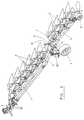
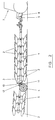
- the elongate plough frame comprises an intermediate frame section 3 provided with wheels 4, as well as a rear plough frame section 5 rearmost carrying a so-called depth wheel 6 (not shown in Figure 2).
- the front plough frame section 1 is coupled to the rear of tractor 7 ( Figure 2) via pull bars 8 and drag shaft 9.
- the wheels 4 of the intermediate section 3 may be raised and lowered by means of a pair of pressure fluid operated (hydraulic) cylinders 10. This set of wheels 4 are controlled by a manoeuvring valve (not shown) within the tractor 7.
- the elongate plough frame is of an articulated construction, the articulation being effected by means of a horizontal pivot 11 supported by the intermediate frame section 3 (and extending generally perpendicular to the ploughing direction) and about which the rear plough frame section 5 may tilt up and down.
- the rear plough frame section 5 may be raised and lowered.
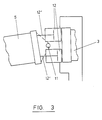
- the tilting of the rear plough frame section 5 is effected by means of two pressure fluid operated actuator means (such as hydraulic cylinders) 12 - see Figure 3, said actuator means 12 being controlled by means of a hydraulic control circuit according to the invention and as disclosed in Figure 4.
- actuator means 12 such as hydraulic cylinders
- Figure 3 is a detail view showing part only of the hydraulic control circuit to control the attitude of the rear plough frame section 5 about horizontal pivot 11.
- the actuators 12 can operate in a first mode to allow limited pivotal movement of the rear frame section and can operate in a second mode to prevent such pivotal movement. When they allow pivotal movement, the rear frame section can pivot about horizontal pivot 11 in order to follow undulations and unevennesses in the ground which is being ploughed.
- the preferred embodiment of the invention disclosed herein utilises the hydraulic depth control circuit shown in Figure 4, and which is applied to a semi-mounted reversible plough of the type described above with reference to Figures 1 to 3.
- This preferred embodiment is particularly useful to control the ploughing depth of the ploughing bodies carried by the rear frame section, and especially when the number of plough bodies on the rear frame section is reduced i.e. there are only a few plough bodies and / or during encountering heavy soil conditions. In these situations, there can be a tendency for the ploughing depth of the plough bodies carried by the rear frame section not to be as deep as is required.
- the preferred embodiment of the invention therefore provides a means whereby the uppermost of the cylinders (at any instance for right or left handed ploughing) is arranged to press continuously against the rear frame section 5 i.e. downwardly about pivot 11 so that the plough bodies carried by the rear frame section can always be held in the required ploughing depth position.
- the force applied by the cylinders (actuator) must be sufficiently large that the rear frame section with the plough bodies is pressed downwardly to the required ploughing depth. However, this force should not be too large, and particularly not so large that there should be any tendency for the reaction force from the ground to tend to press the front end of the rear frame section upwardly.
- the force which is applied by the actuator is therefore arranged to be made adjustable by any convenient manual or automatically operating device controlling the operation of the hydraulic control circuit shown in Figure 4.
- the regulator When manual control is satisfactory, this can be achieved by providing a regulator which can be adjusted manually by the driver of the tractor.
- the regulator can be connected to an adaptive electronic measurement and control system.
- the plough is still capable of adjusting itself to undulations and unevennesses in the surface of the ground being ploughed, with the respective cylinder rods moving in and out to compensate automatically.
- the rear frame section 5 is hinged to the rear of the intermediate frame section 3 via horizontal pivot 11, and actuator cylinders 18 and 19 control the attitude of the frame section 5 about pivot 11 via corresponding movement of the piston rods 12' connected to pistons 12 in the cylinders 18 and 19.
- a 4/3 way valve 16 controls the operation of the cylinders 18 and 19, depending upon which of the three positions shown (A, B, C) is taken up.
- valve 16 is mechanically operated by a toggle mechanism 17, and the arrangement is such that valve 16 can only be operated when the plough is either in the right hand ploughing position shown in Figure 1, or the left hand ploughing position, and in addition when the toggle mechanism 17 is in its operating position.
- the toggle mechanism 17 is arranged to be operated by the arm 13 which controls the depth of the depth control wheel 6, and toggle mechanism 17 is moved into its inoperative position by the wheel arm 13 only when the rear frame section 5 is in its highest position with the plough bodies out of the ground as shown in Figure 2. However, the toggle mechanism 17 is moved into its operating position only when the rear frame section is in the lowest position.
- the valve 16 is mounted on a part of the plough which carries out movement during turning i.e. during plough body reversal, and the position of the valve 16 is such that it can be operated by the toggle mechanism 17 on one side when the plough is in the left side ploughing position, and is operated by the toggle mechanism 17 on the other side when the plough is in the right side ploughing position.
- a hydraulic accumulator 26 is provided in the hydraulic circuit to maintain hydraulic pressure in the system on the pressure side.
- the pressure in the system is regulated by a pressure regulator 20, which can be adjusted manually by the driver of the tractor, or automatically by connecting the regulator 20 to an adaptive electronic measurement and control system.
- a check valve 22 is arranged between pressure regulator 20 and the control valve 16 to lock the pressure in the system, whereas a further check valve 24 ensures that the high pressure tractor system does not come into communication with the low pressure part of the system.
- An accumulator 25 acts as a reservoir for the varying amounts of oil in the system.
- a throttle valve 23 arranged adjacent to and upstream of the pressure regulator 20 ensures that the pressure regulator 20 does not shut-off the oil flow, if there should be any pressure surges when a tractor mounted valve 21 is opened.
- Depth control wheel 6 mounted at the rear end of rear frame section 5 has its height controlled via wheel control arm 13 and connecting rod 15 of a control cylinder 14. Hydraulic pressure fluid is supplied to the system from the hydraulic pump P of the tractor, and controlled by the valve 21 and with return to tank T. The component parts of the hydraulic control system have now been described, and the mode of operation of the system will now be described below.
- the pressure in the system, and therefore the force of the actuator cylinders is controlled so as to be not large enough to hold the weight of the rear frame section, and neither is it able to withstand any substantial force generated by the depth control wheel 6.
- the rear frame section therefore has the plough bodies pressed into the ground surface with a sufficient force, and yet is able to follow undulations in the field surface.
- the rods 12' can therefore move in and out of the cylinders 18 and 19 to compensate for this movement of the rear frame section 3 about pivot 11 , and the volume on both sides of the pistons 12 will ?.
- These variations are taken-up by the accumulators 25 and 26.
- Accumulator 25 is preloaded with a low pressure.
- the valve 21 When the plough has come to the end of the furrow, and is going to be lifted out of the ground, the valve 21 is operated by the driver to the switching position C.
- the accumulator 25 then empties to the tank T, and the accumulator 26 becomes fully pressurised again.
- the piston rod 15 of cylinder 14 acts on wheel arm 13 and therefore moves the wheel 6 downwardly in order to raise the rear end of the rear frame section. In conjunction with the lifting movement of the intermediate frame section 3 by lowering of the wheels 4, this causes the plough bodies to be lifted out of the ground.
- the rear frame section tends to rotate downwardly about pivot 11, by its own weight and by the cylinder rod 12' following after and pressing out until the rear frame section stops against an abutment (not shown).
- the plough can now be lowered into the ground again, which is done by switching the valve 21 so that the switching position A becomes active and the cylinder rod 12' is retracted.
- the toggle mechanism 17 is once again switched into operating position.
- the control valve 16 has also been turned together with the plough and it is the switching position A that is now made active.
- the plough has now returned to the starting position, with the difference that the plough is now in a left hand ploughing position and cylinder 19 is uppermost and has its control rod 12' which is uppermost and which is pressing against the rear frame section 5 above the pivot 11 in order to press the rear frame section downwardly to maintain a required ploughing body depth.
- the toggle mechanism 17 Because of the toggle mechanism 17, it is possible to regulate the ploughing depth during the ploughing operation.
- the toggle mechanism 17 only switches the valve 16 when the plough is in the highest or in the lowest position, and the plough can therefore be regulated by the depth control wheels between these two positions without switching the valve 16.
- the drag shaft 9 When the plough comes to the end of the furrow, the drag shaft 9 is lifted, so that the plough front will become free of the soil. Thereafter, the intermediate section 3 is lifted by means of the actuators 10 via the wheels 4. Because of the pivot 11, the rear plough frame section 5 still occupies a correct ploughing depth by means of the depth wheel 6. However, when the intermediate frame section 3 has been lifted up sufficiently, the rear section will also be brought to a level above ground level.
- the rear plough frame section 5 will occupy an elevated (swung-up) position, such as shown in Figure 2.
- the movements take place in the opposite order.
- the pull bars 8 of the tractor 7 are lowered and then the intermediate frame section 3.
- the rear plough frame section 5 will be lowered such that it, once more, takes a correct ploughing position.
- the rear plough frame section 5 may, once more, tilt about pivot 11 to follow the contour of the ground, but with a controlled biasing force urging the rear frame section 5 downwardly about the pivot to maintain a required ploughing body depth of the plough bodies carried by the rear frame section.
- the drag shaft 9, the intermediate wheels 4 and the depth wheel 6 determined the ploughing depth.
Landscapes
- Life Sciences & Earth Sciences (AREA)
- Engineering & Computer Science (AREA)
- Mechanical Engineering (AREA)
- Soil Sciences (AREA)
- Environmental Sciences (AREA)
- Soil Working Implements (AREA)
- Farming Of Fish And Shellfish (AREA)
- Transmission Devices (AREA)
- Compression Or Coding Systems Of Tv Signals (AREA)
- Circuit Arrangement For Electric Light Sources In General (AREA)
- Micro-Organisms Or Cultivation Processes Thereof (AREA)
- Lifting Devices For Agricultural Implements (AREA)
Claims (8)
- Charrue à socs multiples comprenant un châssis de charrue allongé présentant une section de châssis avant (1, 3) susceptible d'être reliée, à son extrémité avant (9), à l'arrière d'un véhicule de traction (7), une section de châssis arrière (5) accouplée de façon pivotante, en son extrémité avant, à l'arrière de la section avant (13) afin de pouvoir pivoter vers le haut et vers le bas, par rapport à la section avant, de manière à épouser toute irrégularité du sol en cours de labourage, et une pluralité de socs (2) montés sur les sections de châssis (1, 3, 5), un dispositif d'actionnement à commande hydraulique (18, 19, 12') étant accouplé à la section de châssis arrière est étant conçu pour entraíner la section de châssis à pivoter vers le bas sur le pivot horizontal (11) et pour maintenir ainsi les porte-socs (21) supportés par la section de châssis arrière (5) à une profondeur de labourage requise, caractérisée en ce qu'un circuit de commande hydraulique est connecté au dispositif d'actionnement et comporte un régulateur de pression (20) commandant la pression hydraulique fournie au dispositif d'actionnement (12, 19, 12'), de sorte qu'est appliquée, sur la section de châssis arrière, une force de poussée commandée maintenant la profondeur de labourage requise pour les socs, mais qui peut être neutralisée de manière à permettre à la section de châssis arrière (5) de pivoter afin d'épouser les contours du sol en cours de labourage.
- Charrue selon la revendication 1, dans laquelle le dispositif d'actionnement comprend deux cylindres (18, 19) positionnés l'un au-dessus, et l'autre au-dessous du pivot (11), qui est globalement horizontal.
- Charrue selon les revendications 1 ou 2, se présentant sous la forme d'une charrue réversible semi-portée.
- Charrue selon la revendication 3, dans laquelle la section de châssis arrière (5) est accouplée, indirectement, à la section de châssis avant (1), au moyen d'une section de châssis intermédiaire (3) courte, qui constitue une prolongation, vers l'arrière, de la section de châssis avant.
- Charrue selon la revendication 4, dans laquelle la section intermédiaire (3) est reliée, de façon pivotante, en son extrémité avant, à l'arrière de la section de châssis avant (1) et, en son extrémité arrière, à l'avant de la section de châssis arrière (5), chaque connexion pivotante étant constituée d'un pivot vertical qui permet un mouvement de pivotement relatif, latéral, globalement horizontal, de s'effectuer à chaque renversement du corps de la charrue.
- Charrue selon l'une quelconque des revendications 2 à 5, dans laquelle une vanne de commande (16) à 4/3 voies commande l'acheminement d'un fluide sous pression vers les cylindres (18, 19) des dispositifs d'actionnement et qui peut fonctionner, dans un premier mode (C), pour étendre la tige 12' de l'un des cylindres (18) et, dans un deuxième mode (A), pour étendre la tige (12') de l'autre cylindre (19) et, dans un troisième mode (B) pour bloquer la fourniture de fluide en direction ou en provenance des cylindres (18, 19).
- Charrue selon la revendication 6, dans laquelle la vanne de commande (16) est montée sur une partie mobile du châssis d'une charrue réversible, et une liaison à genouillère (17) est conçue pour ne faire fonctionner la vanne de commande (16) que lorsque la charrue a été complètement placée dans l'une ou l'autre de ses deux positions de labourage.
- Charrue selon la revendication 7, dans laquelle la liaison à genouillère (17) est couplée à un bras de commande (13) sur lequel est monté le volant de commande de profondeur (6) de la section de châssis arrière (5), et est déclenchée dans un état opératoire lorsque le volant de commande de profondeur (6) est réglé en position de labourage.
Applications Claiming Priority (3)
| Application Number | Priority Date | Filing Date | Title |
|---|---|---|---|
| GB939309166A GB9309166D0 (en) | 1993-05-04 | 1993-05-04 | Multi-share plough |
| GB9309166 | 1993-05-04 | ||
| PCT/GB1994/000945 WO1994024842A1 (fr) | 1993-05-04 | 1994-05-03 | Charrue a socs multiples |
Publications (2)
| Publication Number | Publication Date |
|---|---|
| EP0648071A1 EP0648071A1 (fr) | 1995-04-19 |
| EP0648071B1 true EP0648071B1 (fr) | 1998-12-16 |
Family
ID=10734898
Family Applications (1)
| Application Number | Title | Priority Date | Filing Date |
|---|---|---|---|
| EP94913758A Expired - Lifetime EP0648071B1 (fr) | 1993-05-04 | 1994-05-03 | Charrue a socs multiples |
Country Status (6)
| Country | Link |
|---|---|
| US (1) | US5603381A (fr) |
| EP (1) | EP0648071B1 (fr) |
| AT (1) | ATE174466T1 (fr) |
| DE (1) | DE69415260T2 (fr) |
| GB (1) | GB9309166D0 (fr) |
| WO (1) | WO1994024842A1 (fr) |
Families Citing this family (11)
| Publication number | Priority date | Publication date | Assignee | Title |
|---|---|---|---|---|
| US5701960A (en) * | 1993-07-10 | 1997-12-30 | Kverneland Klepp As | Reversible Plough |
| US5685378A (en) * | 1995-02-10 | 1997-11-11 | Kverneland Klepp As | Multiple section reversible plough |
| FR2734688B1 (fr) * | 1995-05-29 | 1998-02-20 | Gregoire & Cie Besson | Charrue multi-socs reversible semi-portee |
| US7419784B2 (en) * | 2002-04-02 | 2008-09-02 | Dubrow Robert S | Methods, systems and apparatus for separation and isolation of one or more sample components of a sample biological material |
| US7066279B2 (en) | 2004-11-08 | 2006-06-27 | Earth Tool Company, L.L.C. | Pneumatic ground piercing tool |
| US8157473B2 (en) * | 2009-04-23 | 2012-04-17 | M.A.S. Markers, Incorporated | Apparatus and method for highway marker removal |
| DE102010019819B4 (de) * | 2010-05-08 | 2014-09-18 | Lemken Gmbh & Co. Kg | Aufsatteldrehpflug |
| US20130062083A1 (en) * | 2011-09-14 | 2013-03-14 | Robert T. Casper | Agricultural implement drawbar mechanism |
| NO336787B1 (no) | 2013-12-30 | 2015-11-02 | Kverneland Group Operations Norway As | Et beltearrangement for dybdekontroll av et jordarbeidende redskap |
| CN107409496A (zh) * | 2017-09-14 | 2017-12-01 | 山东农业大学 | 一种翻转犁 |
| IT202000017923A1 (it) * | 2020-07-23 | 2022-01-23 | Maschio Gaspardo Spa | Aratro reversibile |
Family Cites Families (10)
| Publication number | Priority date | Publication date | Assignee | Title |
|---|---|---|---|---|
| DE2248186A1 (de) * | 1972-09-30 | 1974-04-25 | Rabewerk Clausing Heinrich | Beetpflug |
| US4648466A (en) * | 1984-06-13 | 1987-03-10 | Baker Christopher J | Furrow opener operating apparatus |
| FR2616999B1 (fr) * | 1987-06-29 | 1991-03-29 | Gregoire Besson Cie Sarl Ets | Perfectionnement aux charrues multi-socs, reversibles, semi-portees |
| US5065681A (en) * | 1990-10-10 | 1991-11-19 | Deere & Company | Hydraulic down pressure structure for an implement with multiple ground engaging tools |
| GB2264031B (en) * | 1992-01-23 | 1994-08-31 | Kverneland Klepp As | Adjusting devices for a semi-mounted plough |
| GB2264216B (en) * | 1992-02-15 | 1995-06-21 | Kverneland Klepp As | Multi-share plough |
| DE9205779U1 (de) * | 1992-02-21 | 1992-07-02 | Rabewerk GmbH + Co, 4515 Bad Essen | Aufsattel- oder Anhänge-Drehpflug |
| US5277257A (en) * | 1992-10-05 | 1994-01-11 | Deere & Company | Depth control mechanism for an implement |
| US5339906A (en) * | 1993-01-08 | 1994-08-23 | Deere & Company | Positon feedback mechanism for an implement |
| DE9302221U1 (de) * | 1993-02-17 | 1993-04-08 | Rabewerk GmbH + Co, 4515 Bad Essen | Drehpflug |
-
1993
- 1993-05-04 GB GB939309166A patent/GB9309166D0/en active Pending
-
1994
- 1994-05-03 WO PCT/GB1994/000945 patent/WO1994024842A1/fr not_active Ceased
- 1994-05-03 US US08/362,540 patent/US5603381A/en not_active Expired - Fee Related
- 1994-05-03 AT AT94913758T patent/ATE174466T1/de not_active IP Right Cessation
- 1994-05-03 DE DE69415260T patent/DE69415260T2/de not_active Expired - Fee Related
- 1994-05-03 EP EP94913758A patent/EP0648071B1/fr not_active Expired - Lifetime
Also Published As
| Publication number | Publication date |
|---|---|
| US5603381A (en) | 1997-02-18 |
| DE69415260D1 (de) | 1999-01-28 |
| EP0648071A1 (fr) | 1995-04-19 |
| GB9309166D0 (en) | 1993-06-16 |
| DE69415260T2 (de) | 1999-04-29 |
| WO1994024842A1 (fr) | 1994-11-10 |
| ATE174466T1 (de) | 1999-01-15 |
Similar Documents
| Publication | Publication Date | Title |
|---|---|---|
| US6302220B1 (en) | Agricultural ground working implement with hydraulic downpressure circuit | |
| EP0648071B1 (fr) | Charrue a socs multiples | |
| AU745933B2 (en) | Electrohydraulic control of implement lift cylinders | |
| EP0076611B1 (fr) | Attelage pour tracteur | |
| EP2055171B1 (fr) | Système de suspension pour une tête de coupe flottante sur un outil agricole | |
| CA2252276C (fr) | Outil d'agriculture ailete avec un systeme de controle headlands | |
| US11466417B2 (en) | Plow assembly | |
| US4317489A (en) | Ground-working implement and lift linkage therefor | |
| US3630290A (en) | Hydraulic power lift system for tractor and implement | |
| US3663032A (en) | Hydraulic depth control for agricultural implements | |
| US4121852A (en) | Releasably retained hinged plow | |
| US4817730A (en) | Hydraulic weight transfer system for an implement with a lift assist wheel | |
| US5024281A (en) | Reversible moldboard plow | |
| US5381866A (en) | Multi-share plough | |
| US2887167A (en) | Hitch device | |
| US2666376A (en) | Tractor mounted two-way plow | |
| US6971453B2 (en) | Control system for a three point implement hitch assembly | |
| CN116171104B (zh) | 可翻转的耕犁 | |
| US3731749A (en) | Towed plow | |
| US2969119A (en) | Implement positioning device | |
| EP0712270B1 (fr) | Circuit de commande de pression destine a une charrue reversible couplee a plusieurs dispositifs de preparation des sols | |
| EP1080622A1 (fr) | Charrue réversible | |
| CA2252293C (fr) | Instrument agraire pour travailler le sol avec un circuit hydraulique a basse pression | |
| GB2088682A (en) | Reversible plough | |
| JPS5991805A (ja) | 農作業機用角度制御装置 |
Legal Events
| Date | Code | Title | Description |
|---|---|---|---|
| PUAI | Public reference made under article 153(3) epc to a published international application that has entered the european phase |
Free format text: ORIGINAL CODE: 0009012 |
|
| 17P | Request for examination filed |
Effective date: 19941215 |
|
| AK | Designated contracting states |
Kind code of ref document: A1 Designated state(s): AT DE FR GB SE |
|
| 17Q | First examination report despatched |
Effective date: 19961121 |
|
| GRAG | Despatch of communication of intention to grant |
Free format text: ORIGINAL CODE: EPIDOS AGRA |
|
| GRAG | Despatch of communication of intention to grant |
Free format text: ORIGINAL CODE: EPIDOS AGRA |
|
| GRAH | Despatch of communication of intention to grant a patent |
Free format text: ORIGINAL CODE: EPIDOS IGRA |
|
| GRAH | Despatch of communication of intention to grant a patent |
Free format text: ORIGINAL CODE: EPIDOS IGRA |
|
| GRAA | (expected) grant |
Free format text: ORIGINAL CODE: 0009210 |
|
| AK | Designated contracting states |
Kind code of ref document: B1 Designated state(s): AT DE FR GB SE |
|
| REF | Corresponds to: |
Ref document number: 174466 Country of ref document: AT Date of ref document: 19990115 Kind code of ref document: T |
|
| REF | Corresponds to: |
Ref document number: 69415260 Country of ref document: DE Date of ref document: 19990128 |
|
| ET | Fr: translation filed | ||
| PLBE | No opposition filed within time limit |
Free format text: ORIGINAL CODE: 0009261 |
|
| STAA | Information on the status of an ep patent application or granted ep patent |
Free format text: STATUS: NO OPPOSITION FILED WITHIN TIME LIMIT |
|
| 26N | No opposition filed | ||
| PGFP | Annual fee paid to national office [announced via postgrant information from national office to epo] |
Ref country code: AT Payment date: 20000407 Year of fee payment: 7 |
|
| PGFP | Annual fee paid to national office [announced via postgrant information from national office to epo] |
Ref country code: FR Payment date: 20000411 Year of fee payment: 7 |
|
| PGFP | Annual fee paid to national office [announced via postgrant information from national office to epo] |
Ref country code: SE Payment date: 20000417 Year of fee payment: 7 |
|
| PGFP | Annual fee paid to national office [announced via postgrant information from national office to epo] |
Ref country code: DE Payment date: 20000425 Year of fee payment: 7 |
|
| PGFP | Annual fee paid to national office [announced via postgrant information from national office to epo] |
Ref country code: GB Payment date: 20000428 Year of fee payment: 7 |
|
| PG25 | Lapsed in a contracting state [announced via postgrant information from national office to epo] |
Ref country code: GB Free format text: LAPSE BECAUSE OF NON-PAYMENT OF DUE FEES Effective date: 20010503 Ref country code: AT Free format text: LAPSE BECAUSE OF NON-PAYMENT OF DUE FEES Effective date: 20010503 |
|
| PG25 | Lapsed in a contracting state [announced via postgrant information from national office to epo] |
Ref country code: SE Free format text: LAPSE BECAUSE OF NON-PAYMENT OF DUE FEES Effective date: 20010504 |
|
| GBPC | Gb: european patent ceased through non-payment of renewal fee |
Effective date: 20010503 |
|
| PG25 | Lapsed in a contracting state [announced via postgrant information from national office to epo] |
Ref country code: FR Free format text: LAPSE BECAUSE OF NON-PAYMENT OF DUE FEES Effective date: 20020131 |
|
| PG25 | Lapsed in a contracting state [announced via postgrant information from national office to epo] |
Ref country code: DE Free format text: LAPSE BECAUSE OF NON-PAYMENT OF DUE FEES Effective date: 20020301 |