EP0648513B1 - Infusionsvorrichtung - Google Patents
Infusionsvorrichtung Download PDFInfo
- Publication number
- EP0648513B1 EP0648513B1 EP19940420277 EP94420277A EP0648513B1 EP 0648513 B1 EP0648513 B1 EP 0648513B1 EP 19940420277 EP19940420277 EP 19940420277 EP 94420277 A EP94420277 A EP 94420277A EP 0648513 B1 EP0648513 B1 EP 0648513B1
- Authority
- EP
- European Patent Office
- Prior art keywords
- liquid
- inlet
- outlet
- check valve
- upstream
- Prior art date
- Legal status (The legal status is an assumption and is not a legal conclusion. Google has not performed a legal analysis and makes no representation as to the accuracy of the status listed.)
- Expired - Lifetime
Links
- 238000010999 medical injection Methods 0.000 title description 2
- 239000007788 liquid Substances 0.000 claims description 91
- 238000011144 upstream manufacturing Methods 0.000 claims description 55
- 238000002347 injection Methods 0.000 claims description 37
- 239000007924 injection Substances 0.000 claims description 37
- 239000000463 material Substances 0.000 claims description 6
- 238000001990 intravenous administration Methods 0.000 claims description 3
- 239000012780 transparent material Substances 0.000 claims description 3
- 230000004913 activation Effects 0.000 claims 5
- 238000011109 contamination Methods 0.000 description 10
- 239000012530 fluid Substances 0.000 description 9
- 238000007789 sealing Methods 0.000 description 8
- 241000894006 Bacteria Species 0.000 description 3
- 208000031968 Cadaver Diseases 0.000 description 3
- 241000700605 Viruses Species 0.000 description 3
- 201000010099 disease Diseases 0.000 description 3
- 208000037265 diseases, disorders, signs and symptoms Diseases 0.000 description 3
- 239000007864 aqueous solution Substances 0.000 description 2
- 230000035515 penetration Effects 0.000 description 2
- 150000003384 small molecules Chemical class 0.000 description 2
- 208000030507 AIDS Diseases 0.000 description 1
- 102000015696 Interleukins Human genes 0.000 description 1
- 108010063738 Interleukins Proteins 0.000 description 1
- 244000052616 bacterial pathogen Species 0.000 description 1
- 230000005540 biological transmission Effects 0.000 description 1
- 239000008280 blood Substances 0.000 description 1
- 210000004369 blood Anatomy 0.000 description 1
- 238000005202 decontamination Methods 0.000 description 1
- 230000003588 decontaminative effect Effects 0.000 description 1
- 238000013461 design Methods 0.000 description 1
- 238000011161 development Methods 0.000 description 1
- 238000006073 displacement reaction Methods 0.000 description 1
- 230000000694 effects Effects 0.000 description 1
- 230000005489 elastic deformation Effects 0.000 description 1
- 230000005484 gravity Effects 0.000 description 1
- 208000015181 infectious disease Diseases 0.000 description 1
- 230000002458 infectious effect Effects 0.000 description 1
- 238000000034 method Methods 0.000 description 1
- 239000002991 molded plastic Substances 0.000 description 1
- 239000004033 plastic Substances 0.000 description 1
- 229920003023 plastic Polymers 0.000 description 1
- 238000012545 processing Methods 0.000 description 1
- 238000004064 recycling Methods 0.000 description 1
- 238000012360 testing method Methods 0.000 description 1
- 230000000007 visual effect Effects 0.000 description 1
- 238000003466 welding Methods 0.000 description 1
Images


Classifications
-
- A—HUMAN NECESSITIES
- A61—MEDICAL OR VETERINARY SCIENCE; HYGIENE
- A61M—DEVICES FOR INTRODUCING MEDIA INTO, OR ONTO, THE BODY; DEVICES FOR TRANSDUCING BODY MEDIA OR FOR TAKING MEDIA FROM THE BODY; DEVICES FOR PRODUCING OR ENDING SLEEP OR STUPOR
- A61M39/00—Tubes, tube connectors, tube couplings, valves, access sites or the like, specially adapted for medical use
- A61M39/22—Valves or arrangement of valves
- A61M39/24—Check- or non-return valves
- A61M2039/242—Check- or non-return valves designed to open when a predetermined pressure or flow rate has been reached, e.g. check valve actuated by fluid
-
- A—HUMAN NECESSITIES
- A61—MEDICAL OR VETERINARY SCIENCE; HYGIENE
- A61M—DEVICES FOR INTRODUCING MEDIA INTO, OR ONTO, THE BODY; DEVICES FOR TRANSDUCING BODY MEDIA OR FOR TAKING MEDIA FROM THE BODY; DEVICES FOR PRODUCING OR ENDING SLEEP OR STUPOR
- A61M39/00—Tubes, tube connectors, tube couplings, valves, access sites or the like, specially adapted for medical use
- A61M39/22—Valves or arrangement of valves
- A61M39/24—Check- or non-return valves
- A61M2039/2433—Valve comprising a resilient or deformable element, e.g. flap valve, deformable disc
- A61M2039/2446—Flexible disc
- A61M2039/2466—Flexible disc being fixed in its center
Definitions
- the present invention relates to devices for medical use allowing the injection of liquids into the human body.
- Liquid injections are usually done by means of an injection line such as a cathelon, a catheter, a needle hypodermic or intravenous.
- This injection pipe intended to penetrate in the human body, is connected to a syringe or a pipe liquid injection to inject the liquid from a reservoir.
- the problem proposed by the present invention is to design a new structure of a device for medical use for the injection of liquids which make it possible to avoid throwing after treatment of a patient the the entire injection device, while eliminating any risk of contamination between successive patients.
- the anti-contamination effectiveness of the device must be ensured both by authorizing high injection rates, i.e. flow rates of the order of 10 ml / s or more, and effectively opposing any transmission of infectious germs, even small ones, within usual conditions of use, especially in the absence of flow.
- the anti-contamination effectiveness of the device must be able to be easily checked during use in order to detect as soon as possible any faults and possible risks of contamination between successive patients.
- Another object of the invention is to facilitate the use of the injection device, avoiding the escape of fluids during disconnections, especially in devices with liquid source under pressure such as devices used in radiology.
- the device of the invention must also be compatible with an injection set that can be filled several times.
- the invention provides a device for medical use for the injection of liquids according to claim 1
- the removable connector itself constitutes a disposable element, which prevents all retrograde contamination, that is to say all passages of fluids, bacteria or viruses from the patient's body to the inlet nozzle allowing its connection to an outlet pipe of the liquid supply device. This ensures that the liquid supply device with its outlet pipe is not itself not contaminated, and that it can be used for several patients successive, provided that each time a new removable connector is fitted or decontaminated.
- the upstream and downstream tubular parts are made of a transparent material, revealing the appearance of liquid flowing through them.
- We can thus, by a simple visual control, ensure that there is no contamination upstream of the valve when a contamination is visible downstream of the valve, for example during a red or pink coloration in the presence of blood.
- the upstream tubular part is intended to contain a liquid under pressure. Liquid under pressure naturally tends to repel walls of the tubular parts, which can then contain liquid in excess. When disconnecting the removable connector, the natural elasticity the walls of the tubular parts flush out the excess liquid, which tends to flow outward. This results in an escape of one or several drops of liquid.
- a device for medical use for injecting liquids usually includes an injection line 1 such as a cathelon, catheter, hypodermic needle or intravenous, connected by means of conduction pipelines liquids 2 to a liquid supply device 3.
- the device liquid supply 3 is adapted to force the liquid under pressure in the means for conduction of liquids 2 and the injection pipe 1, for injecting the liquid into the body of a patient.
- the device for injecting liquids comprises a removable connector 4, inserted in the means of pipes of conduction of liquids 2 between the outlet pipe 5 of the device liquid supply 3 and the inlet 6 of the injection pipe 1.
- the removable connector 4 comprises a threshold non-return valve 7, adapted to prevent the flow of liquid from its outlet 13 towards its inlet 11, and adapted to allow the flow of liquid from its inlet 11 to its outlet 13 as illustrated by arrow 8 when the liquid pressure at its input exceeds the output pressure by a higher value or equal to a determined trigger threshold S.
- the removable connector 4 further comprises a tubular part upstream 9, a first end of which is provided with an inlet nozzle 10 adapted to allow its disconnectable connection to a outlet 5 of the liquid supply device 3, the second of which end is connected to inlet 11 of the threshold non-return valve 7.
- a simple upstream tube preferably with internal section generally constant over its entire length, connects the first and second ends upstream tubular part 9.
- the removable connector 4 also includes a tubular part downstream 12, a first end of which is connected to outlet 13 of the non-return valve with threshold 7, and the second end of which is provided with a outlet nozzle 14 suitable for direct disconnectable connection to the inlet of the injection pipe 1.
- a simple downstream tube preferably at interior section generally constant over its entire length, connects the first and second ends of downstream tubular part 12.
- the inlet nozzle 10 can be connected directly to the liquid supply device 3, or indirectly by the outlet pipe 5.
- the removable connector 4 may include inlet 10 and outlet 14 tips shaped and adapted to be removably connected to various pipes, the ends of which include similar end fittings.
- male end caps and end caps should be used females in such a way that we cannot reverse the input and the outlet of the removable connector 4, in order to respect the direction of propagation 8 some cash.
- the inlet nozzle 10 is a female end piece, while the outlet end piece 14 is a end piece male.
- the outlet nozzle 14 adapts to a conduit inlet 6 injection fitted with a corresponding female nozzle
- the inlet nozzle 10 adapts to a male connector provided at the outlet of the supply device in liquid 3 or at the outlet of the outlet pipe 5 which connects the liquid supply device 3 and the removable connector 4.
- the upstream tubular part 9 and the downstream tubular part 12 are preferably made of a transparent material, revealing the appearance of the liquid flowing through them.
- At least the downstream tubular part 12 is produced by a material giving it an adapted flexibility. Its length can advantageously be between 10 and 30 centimeters.
- the part upstream tubular 9 can also be flexible, to increase the possibilities of displacement and orientation of the injection pipe 1.
- the upstream tubular part 9 has a length reduced, for example between 1 and 4 centimeters approximately.
- this upstream tubular part can be made of a material relatively deformable, so that it can be flexible.
- the deformation of the wall of upstream tubular part 9 under the effect of the pressure of the liquid it contains causes a slight increase in his capacity.
- the wall of upstream tubular part 9 tends to regain its shape, driving out the excess liquid it contains and which flows outside.
- the upstream tubular part 9 must be short, as shown above.
- the trigger threshold S of the threshold non-return valve 7 is advantageously between 50 and 400 hecto Pascal. Thanks to such a threshold trigger, we make sure that no fluid, no bacteria, no virus cannot progress from the downstream tubular part 12 to the upstream tubular part 9, even when the supply device liquid 3 is at rest or when the upstream tubular part 9 is at a pressure lower than or equal to the pressure in the downstream tubular part 12. Passage through the threshold non-return valve 7 is only made when the pressure in the upstream tubular part 9 is significantly higher than the pressure in the downstream tubular part 12, so that the direction of progression of the liquid in the valve 7 is necessarily in accordance with the direction indicated by arrow 8, from upstream to downstream.
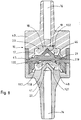
- FIG. 3 illustrates a first embodiment of the valve non-return threshold 7, made entirely of plastic.
- the valve as shown comprises a valve body 15 in two parts 40 and 41 holes in a through channel 16, the central part of which forms a shutter chamber 17.
- the shutter chamber 17 includes a seat intermediate 20 with sharp edge formed at the junction of an upstream portion 42 a smaller section sealing chamber and a downstream portion 43 of wider section sealing chamber.
- the shutter chamber 17 contains an elastically flexible transverse obturator disc 18 of which the periphery of the upstream face 19 is supported on the seat 20 with a sharp edge of the valve body 15 and whose downstream face 21 is axially constrained upstream by a central needle 22 of the valve body 15.
- the obturator disc 18 By elastic deformation under the action of needle 22, the obturator disc 18 is pressed against the seat 20. It is understood that the shutter disc 18 prohibits the passage of fluid from outlet 13 to inlet 11, because any excess fluid pressure in outlet 13 presses the obturator disc 18 against the seat 20. On the other hand, the shutter disc 18 authorizes the passage of fluid from inlet 11 to outlet 13 when the overpressure at inlet 11 is sufficient to elastically flex the periphery of the shutter disc 18 and to move it slightly away from the seat 20.
- the setting of the trigger threshold S is carried out by the choice appropriate thickness and hardness of the shutter disc 18.
- the body valve 15 is formed by the axial assembly of two parts, a part 40 forming the first upstream half of the valve body, a part 41 forming the second downstream half of the valve body.
- the two pieces 40 and 41 have annular ribs, as shown, shaped to fit into each other and create the room at the interface shutter 17.
- the assembly of parts 40 and 41 can, for example, be performed by ultrasonic welding, or by any other means.
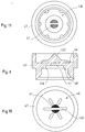
- FIGS 4 and 5 illustrate the part 40 forming half upstream of the valve body.
- the through channel 16 comprises, at the entrance to the sealing chamber 17, a diametrical bridge 44 intended to cooperate with the obturator disc 18.
- the fluid can pass freely on either side of the diametrical bridge 44.
- FIGS 6 and 7 illustrate the part 41 constituting half downstream of the valve body.
- the needle 22 is a diametral rib generally flat with triangular longitudinal profile, as shown. Liquids can pass on either side of the rib forming the needle 22, from the sealing chamber 17 to the canal crossing 16.
- FIG. 8 illustrates, in longitudinal section, a second mode of preferred embodiment of a threshold check valve according to the present invention.
- a threshold check valve having a risk of passage less than 10 -5 .
- This risk of passage is measured according to the following test: downstream of the non-return valve, an aqueous solution of a product whose molecules are small in size is introduced, for example the product 3 H-2 deoxy-D-glucose, or the interleukin 6rH product. On the upstream side, an aqueous solution devoid of the small molecule product is introduced. The device is kept in this state for a determined period, for example 3 hours, at the end of which the quantity of small molecules which have been able to pass from the upstream side of the non-return valve is measured.
- FIG. 8 makes it possible to reduce the risk of passing to a value of less than 10 -5 , thus providing satisfactory safety for the usual applications of medical injections.
- the valve body 15 is produced by axial assembly of three parts 40, 41 and 45.
- Part 40 can advantageously be identical to the upstream part 40 of the embodiment of Figure 3.
- the part 41 may advantageously be identical downstream part 41 of the embodiment of FIG. 3.
- Part 45 is an intermediate part 45 inserted between the upstream part 40 and the part downstream 41.
- the intermediate piece 45 has an upstream face 46, also illustrated in FIG. 10, having the same shape as the upstream face of the downstream part 41, that is to say with a central needle 122 similar to the needle 22, in the shape of a diametrical rib, and with lateral passages 47 for the passage of liquid on either side of the rib forming the needle 122.
- the intermediate piece has a downstream face 48, also shown in Figure 11, shaped like the downstream face of the upstream part 40, that is to say with a similar intermediate seat 120 of the seat 20 of the upstream part 40.
- a first sealing chamber 17 is formed between the upstream part 40 and the intermediate part 45
- a second identical sealing chamber 117 is formed between the part intermediate 45 and the downstream part 41.
- the first sealing chamber 17 contains the first disc shutter 18, the periphery of the upstream face 19 is supported on the first intermediate seat 20 of the valve body 15, and whose downstream face 21 is axially constrained upstream by the central needle 122 of the intermediate part 45.
- the second sealing chamber 117 contains a second elastically transverse obturating disc 118 flexible whose periphery of the upstream face 119 is supported on the seat intermediate 120 of intermediate part 45 and whose downstream face 121 is constrained axially upstream by the central needle 22 of the downstream part 41 of the valve body 15.
- the shutter discs 18 and 118 perform a double filling.
- the threshold non-return valve 7, the part upstream tubular 9, downstream tubular part 12 and end pieces 10 and 14 can be made of molded plastics, the materials being chosen to comply with medical standards, to be compatible with the products to be injected and to be sterilizable by the usual methods.
- the liquid injection device comprises, upstream of the removable connector 4, an intermediate supply pipe 23 comprising a branch outlet 24 provided with a second non-return valve 25 with threshold, preventing the ascent of liquid from its outlet 26 to its inlet 27, and authorizing the passage of the liquid downstream when the pressure at the inlet 27 of the second non-return valve 25 exceeds the pressure at its outlet 26 according to a second determined trigger threshold S2.
- the output branch 24 advantageously comprises, downstream of the second non-return valve 25, a short pipe 28 of length less than about two centimeters. This avoids the flow of excess liquid when disconnecting the inlet nozzle 10.
- the intermediate supply line 23 includes in addition to an input branch 29 adapted to connect the input of the branch outlet 24 to outlet pipe 5 of a supply device in liquid 3 provided with means for generating overpressure and depression.
- the intermediate supply line 23 comprises also a filling branch 30 adapted to connect the inlet of the outlet branch 24 to a liquid reservoir 31, the branch of filling 30 being provided with a third non-return valve 32 at third low or zero S3 trigger threshold.
- the device for supplying liquid 3 generates an internal depression, causing a flow of liquid from the reservoir 31, through the third non-return valve 32 and the filling branch 30, and through the inlet branch 29 as far as the liquid supply device 3.
- the device for supplying liquid 3 pushes the liquid back under pressure through the inlet branch 29, the outlet branch 24, the second valve 25, the removable connector 4 and the injection line 1, when the pressure produced by the device liquid supply 3 is sufficient to force the liquid to through the two successive non-return valves 25 and 7.
- the second valve non-return 25 prevents the flow of liquid from the reservoir 31 to the output 26, provided that the second threshold S2 of the second valve 25 is higher than the liquid pressure resulting from the position raised tank 31.
- the liquid pressure inside the upstream tubular part 9 may be less than the pressure in the part downstream tubular 12, but the non-return valve 7 prevents any progression liquid, bacteria or virus from downstream to upstream, and prevents contamination of the upstream tubular part 9, of the nozzle input 10 and all the elements upstream.
- the disconnection of the inlet nozzle 10 is sufficient to isolate the fitting removable 4 and the injection pipe 1 relative to the other elements of the device that is not contaminated.
- the injection pipe 1 and the removable connector 4, which are possibly contaminated, are then discarded, or treated by recycling or decontamination.
- the second trigger threshold S2 of the second non-return valve with threshold 25 is less than the first threshold of triggering S of the first non-return valve 7 of the removable connector 4.
Landscapes
- Health & Medical Sciences (AREA)
- Heart & Thoracic Surgery (AREA)
- Pulmonology (AREA)
- Engineering & Computer Science (AREA)
- Anesthesiology (AREA)
- Biomedical Technology (AREA)
- Hematology (AREA)
- Life Sciences & Earth Sciences (AREA)
- Animal Behavior & Ethology (AREA)
- General Health & Medical Sciences (AREA)
- Public Health (AREA)
- Veterinary Medicine (AREA)
- Infusion, Injection, And Reservoir Apparatuses (AREA)
Claims (11)
- Vorrichtung zum medizinischen Gebrauch für die Injektion von Flüssigkeiten, bestehend aus Leitungsmitteln zur Hindurchleitung von Flüssigkeiten und einem Rückschlag-Schwellenventilmittel (7) zum Hindurchleiten von Flüssigkeiten in einer Richtung zwischen dem Ausgang (5) einer Druckflüssigkeit-Versorgungsvorrichtung (3) und dem Eingang (6) einer Injektionsleitung (1), wie bspw. Kathelon, Katheter, subkutane oder intravenöse Nadel, wobei die Vorrichtung dadurch gekennzeichnet ist, daß sie besteht aus:einem lösbaren Anschluß (4), der austauschbar ausgebildet ist aus:einem Rückschlag-Schwellenventilmittel (7), welches zur Verhinderung des Flüssigkeitsflusses von seinem Ausgang (13) gegen seinen Eingang (11) angepaßt ist und zur Ermöglichung des Flüssigkeitsflusses von seinem Eingang (11) gegen seinen Ausgang (13), sobald der Flüssigkeitsdruck an seinem Eingang (11) den Druck am Ausgang (13) um einen Wert übersteigt, der größer oder gleich einer bestimmten Auslöseschwelle (S) ist,einem stromaufwärts verlaufenden rohrförmigen Teil (9) mit einem ersten Ende, das mit einem weiblichen Eingangsansatzstück (10) für einen trennbaren Anschluß an eine Ausgangsleitung (5) der Flüssigkeit-Versorgungsvorrichtung (3) versehen ist, mit einem zweiten Ende, das mit dem Eingang (11) des Rückschlag-Schwellenventilmittels (7) verbunden ist, und mit einer stromaufwärts angeordneten einfachen Röhre, welche das Eingangsansatzstück (10) und den Eingang (11) des Rückschlag-Schwellenventilmittels (7) miteinander verbindet,einem stromabwärts verlaufenden rohrförmigen Teil (12) mit einem ersten Ende, das mit dem Ausgang (13) des Rückschlag-Schwellenventilmittels (7) verbunden ist, mit einem zweiten Ende, das mit einem Ausgangsansatzstück (14) versehen ist, welches für einen trennbaren Anschluß direkt mit dem Eingang (6) der Injektionsleitung (1) angepaßt ist, und mit einer stromabwärts angeordneten einfachen Röhre, welche den Ausgang (13) des Rückschlag-Schwellenventilmittels (7) und das Ausgangsansatzstück (14) miteinander verbindet.
- Vorrichtung nach Anspruch 1, dadurch gekennzeichnet, daß das Rückschlag-Schwellenventilmittel (7) eine erste Verschlußkammer (17) aufweist, die eine erste Verschlußscheibe (18) enthält, und eine zweite Verschlußkammer (117), die eine zweite Verschlußscheibe (118) enthält, wobei die Verschlußkammern (17, 117) aufeinander folgen und die Verschlußscheiben (18, 118) einen Doppelverschluß realisieren.
- Vorrichtung nach Anspruch 2, dadurch gekennzeichnet, daß das Rückschlag-Schwellenventilmittel (7) einen Ventilkörper (15) aufweist, der durch den Zusammenbau von drei Teilen (40, 41, 45) realisiert ist, die mit Leitungen (16) für die Hindurchleitung von Flüssigkeiten durchbohrt sind und die beiden aufeinanderfolgenden Verschlußkammern (17, 117) bilden, die jeweils eine transversal elastisch flexible Verschlußscheibe (18, 118) enthalten, bei welcher der äußere Umfang der stromaufwärts befindlichen Stirnseite (19, 119) an einem Zwischensitz (20, 120) des Ventilkörpers (15) anliegt und deren stromabwärts befindliche Stirnseite (21, 121) axial in der Richtung stromaufwärts durch eine zentrale Injektornadel (22, 122) des Ventilkörpers (15) belastet ist.
- Vorrichtung nach einem der Ansprüche 1 bis 3, dadurch gekennzeichnet, daß die stromaufwärts (9) und stromabwärts (12) verlaufenden rohrförmigen Teile mit einem transparenten Material realisiert sind, welches das Aussehen der sie durchquerenden Flüssigkeit erscheinen läßt.
- Vorrichtung nach einem der Ansprüche 1 bis 4, dadurch gekennzeichnet, daß wenigstens der stromabwärts verlaufende rohrförmige Teil (12) aus einem Material realisiert ist, welches ihm eine Flexibilität verleiht, die der Verschiebung und der Orientierung der Injektionsleitung (1) angepaßt ist.
- Vorrichtung nach Anspruch 5, dadurch gekennzeichnet, daß auch der stromaufwärts verlaufende rohrförmige Teil (9) flexibel ist.
- Vorrichtung nach Anspruch 6, dadurch gekennzeichnet, daß der stromaufwärts verlaufende rohrförmige Teil (9) eine Länge aufweist, die etwa zwischen 1 und 4 cm beträgt.
- Vorrichtung nach einem der Ansprüche 1 bis 5, dadurch gekennzeichnet, daß der stromaufwärts verlaufende rohrförmige Teil (9) aus einem unelastischen Material realisiert ist.
- Vorrichtung nach einem der Ansprüche 1 bis 8, dadurch gekennzeichnet, daß die bestimmte Auslöseschwelle (S) mit zwischen 50 und 400 Hektopascal gebildet ist.
- Vorrichtung nach einem der Ansprüche 1 bis 9, dadurch gekennzeichnet, daß sie weiterhin eine dazwischenliegende Versorgungsleitung (23) aufweist, bestehend aus:einer Ausgangszweigleitung (24), die mit einem zweiten Rückschlag-Schwellenventil (25) versehen ist, welches das Ansteigen der Flüssigkeit von ihrem Ausgang (26) gegen ihren Eingang (27) verhindert und den Durchfluß der Flüssigkeit in der Richtung stromabwärts erlaubt, sobald der Druck am Eingang (27) des zweiten Rückschlagventils (25) den Druck an seinem Ausgang (26) übersteigt gemäß einer zweiten bestimmten Auslöseschwelle (S2), wobei die Ausgangszweigleitung (24) stromabwärts von dem zweiten Rückschlagventil (25) eine kurze Leitung (28) mit einer Länge von weniger als etwa 2 cm aufweist,einer Eingangszweigleitung (29), die für eine Verbindung des Eingangs der Ausgangszweigleitung (24) mit einer Flüssigkeit-Versorgungsvorrichtung (3) angepaßt ist, die mit Mitteln zur Erzeugung eines Überdruckes und eines Unterdruckes versehen ist,einer Füllungszweigleitung (30), die zur Verbindung des Eingangs der Ausgangszweigleitung (24) mit einem Flüssigkeitsreservoir (31) angepaßt ist, wobei die Füllungszweigleitung (30) mit einem dritten Rückschlagventil (32) mit einer schwachen oder nicht vorhandenen Schwelle (S3) versehen ist.
- Vorrichtung nach Anspruch 10, dadurch gekennzeichnet, daß die zweite Auslöseschwelle (S2) des zweiten Rückschlagventils (25) geringer ist als die erste Auslöseschwelle (S) des Rückschlagventils (7) des lösbaren Anschlusses (4).
Applications Claiming Priority (2)
| Application Number | Priority Date | Filing Date | Title |
|---|---|---|---|
| FR9312590A FR2711319B1 (fr) | 1993-10-19 | 1993-10-19 | Dispositif pour l'injection médicale de liquides. |
| FR9312590 | 1993-10-19 |
Publications (2)
| Publication Number | Publication Date |
|---|---|
| EP0648513A1 EP0648513A1 (de) | 1995-04-19 |
| EP0648513B1 true EP0648513B1 (de) | 1998-03-04 |
Family
ID=9452101
Family Applications (1)
| Application Number | Title | Priority Date | Filing Date |
|---|---|---|---|
| EP19940420277 Expired - Lifetime EP0648513B1 (de) | 1993-10-19 | 1994-10-19 | Infusionsvorrichtung |
Country Status (3)
| Country | Link |
|---|---|
| EP (1) | EP0648513B1 (de) |
| DE (1) | DE69408765T2 (de) |
| FR (1) | FR2711319B1 (de) |
Cited By (1)
| Publication number | Priority date | Publication date | Assignee | Title |
|---|---|---|---|---|
| US8777900B2 (en) | 2010-12-14 | 2014-07-15 | Kimberly-Clark Worldwide, Inc. | Ambulatory enteral feeding system |
Families Citing this family (10)
| Publication number | Priority date | Publication date | Assignee | Title |
|---|---|---|---|---|
| DE19545452C1 (de) * | 1995-12-06 | 1996-11-14 | Thomas Michael Jokisch | Rückschlagventil für Fluide mit geringen Druckunterschieden, insbesondere für die Medizintechnik und Aquaristik |
| FR2757069A1 (fr) | 1996-12-18 | 1998-06-19 | Debiotech Sa | Dispositif medical d'injection de liquide |
| US6156025A (en) * | 1999-06-17 | 2000-12-05 | Bracco Research Usa Inc. | Twist valve |
| FR2991881B1 (fr) | 2012-06-13 | 2014-09-05 | Medex Sa | Dispositif d'injection d'un produit liquide comprenant deux demi-coques mobiles en rotation l'une par rapport a l'autre |
| FR2991880B1 (fr) | 2012-06-13 | 2019-11-22 | Medex | Controleur pour l'asservissement d'un dispositif d'injection |
| WO2013186300A2 (fr) | 2012-06-13 | 2013-12-19 | Medex | Ensemble d'injection de produit liquide et visqueux |
| DE202012007884U1 (de) * | 2012-08-20 | 2012-09-07 | Illinois Tool Works Inc. | Einweg-Ventileinrichtung |
| DE102017102586A1 (de) | 2017-02-09 | 2018-08-09 | Eagle Actuator Components Gmbh & Co. Kg | Rückschlagventil |
| CN109125863A (zh) * | 2018-09-30 | 2019-01-04 | 天津伊腾圣杰医疗器械有限公司 | 一种多功能注射组件 |
| WO2025186466A1 (fr) | 2024-03-08 | 2025-09-12 | Guerbet | Double valve |
Family Cites Families (6)
| Publication number | Priority date | Publication date | Assignee | Title |
|---|---|---|---|---|
| US2538662A (en) * | 1950-01-24 | 1951-01-16 | Charles C Abbott | Expendable valve unit for surgical appliances |
| BE775758A (fr) * | 1971-02-12 | 1972-03-16 | American Hospital Supply Corp | Ensemble d'administration medical et procede de distribution deplusieurs liquides medicaux |
| US4114617A (en) * | 1977-02-28 | 1978-09-19 | Turner Thomas D | Apparatus for infusion of a measured volume of blood |
| AU3775578A (en) * | 1977-07-08 | 1980-01-10 | Johnson & Johnson | Vented filter assembly |
| US4573974A (en) * | 1982-12-01 | 1986-03-04 | Baxter Travenol Laboratories, Inc. | Medical administration set enabling sequential delivery of two liquids at different flow rate |
| US5025829A (en) * | 1990-01-29 | 1991-06-25 | Harmac Medical Products, Inc. | Parenteral check valve |
-
1993
- 1993-10-19 FR FR9312590A patent/FR2711319B1/fr not_active Expired - Fee Related
-
1994
- 1994-10-19 EP EP19940420277 patent/EP0648513B1/de not_active Expired - Lifetime
- 1994-10-19 DE DE1994608765 patent/DE69408765T2/de not_active Expired - Lifetime
Cited By (1)
| Publication number | Priority date | Publication date | Assignee | Title |
|---|---|---|---|---|
| US8777900B2 (en) | 2010-12-14 | 2014-07-15 | Kimberly-Clark Worldwide, Inc. | Ambulatory enteral feeding system |
Also Published As
| Publication number | Publication date |
|---|---|
| FR2711319A1 (fr) | 1995-04-28 |
| DE69408765D1 (de) | 1998-04-09 |
| EP0648513A1 (de) | 1995-04-19 |
| DE69408765T2 (de) | 1998-10-08 |
| FR2711319B1 (fr) | 1995-12-08 |
Similar Documents
| Publication | Publication Date | Title |
|---|---|---|
| EP0648513B1 (de) | Infusionsvorrichtung | |
| EP2861276B1 (de) | Anordnung zur injektion eines zähflüssigen produkts | |
| EP0846008B1 (de) | Vorrichtung zur kontinuierlichen injektion | |
| FR2522969A1 (fr) | Connecteur pour tubulure medicale et poche pour solution medicale utilisant ce connecteur | |
| FR2758088A1 (fr) | Dispositif d'injection de liquide medical | |
| EP0854735B1 (de) | Nadellose strahlinjektionsvorrichtung mit übergegossener ampulle | |
| EP0448418A2 (de) | Verbesserungen an implantierbaren vaskularen Anschlussvorrichtungen | |
| FR2593400A1 (fr) | Dispositif d'administration sous-cutanee et procede pour supporter et guider une aiguille de seringue pendant et une fois qu'elle est inseree dans un tel dispositif | |
| FR2522776A1 (fr) | Connecteur pour equipement de dialyse peritoneale ambulatoire continue | |
| FR2988006A1 (fr) | Ensemble securise de transfert de liquide a usage medical | |
| EP2170448A1 (de) | Vorrichtung zur einführung eines katheterführungsdrahts in ein gefäss | |
| HUE029184T2 (en) | Medical valve assembly | |
| FR2561924A1 (fr) | Dispositif de commande d'ecoulement | |
| CA2982611A1 (fr) | Robinet medical, kit comprenant un tel robinet et methode de preparation d'un melange ou d'une emulsion | |
| FR2550704A1 (fr) | Recipient souple pour usage medical, notamment pour dialyse | |
| CH705153A1 (fr) | Mors et système pour envoyer une substance visqueuse et/ou liquide dans la bouche d'un animal. | |
| EP0676214A1 (de) | Infusionsvorrichtung für medizinische Flüssigkeit | |
| FR2475903A1 (en) | Safety coupling for cannulae or catheters - comprises cone penetrating elastomeric disc with slit, which closes passage if coupling breaks | |
| WO2006005855A1 (fr) | Introducteur pour intervention endoluminale | |
| EP0947752B1 (de) | Schwellwertventil | |
| FR2678837A1 (fr) | Dispositif d'injection de precision. | |
| FR2928838A1 (fr) | Dispositif de raccordement/protection de capteur, en particulier pour des lignes biomedicales d'hemodialyse | |
| EP4688044A1 (de) | Tragbare vorrichtung zur erkennung eines hindernisses, überwachung des hindernisses und zerstörung eines katheters | |
| EP3086826B1 (de) | Hydraulikaggregat eines generators von gepulsten oder ungepulsten mittel- und hochdruckstrahlen | |
| FR2627698A1 (fr) | Cartouche d'injection de medicament a utiliser dans un injecteur a vide-compression |
Legal Events
| Date | Code | Title | Description |
|---|---|---|---|
| PUAI | Public reference made under article 153(3) epc to a published international application that has entered the european phase |
Free format text: ORIGINAL CODE: 0009012 |
|
| AK | Designated contracting states |
Kind code of ref document: A1 Designated state(s): BE DE FR GB SE |
|
| 17P | Request for examination filed |
Effective date: 19950905 |
|
| 17Q | First examination report despatched |
Effective date: 19951103 |
|
| RAP1 | Party data changed (applicant data changed or rights of an application transferred) |
Owner name: MEDEX |
|
| GRAG | Despatch of communication of intention to grant |
Free format text: ORIGINAL CODE: EPIDOS AGRA |
|
| GRAG | Despatch of communication of intention to grant |
Free format text: ORIGINAL CODE: EPIDOS AGRA |
|
| GRAH | Despatch of communication of intention to grant a patent |
Free format text: ORIGINAL CODE: EPIDOS IGRA |
|
| GRAH | Despatch of communication of intention to grant a patent |
Free format text: ORIGINAL CODE: EPIDOS IGRA |
|
| GRAA | (expected) grant |
Free format text: ORIGINAL CODE: 0009210 |
|
| AK | Designated contracting states |
Kind code of ref document: B1 Designated state(s): BE DE FR GB SE |
|
| REF | Corresponds to: |
Ref document number: 69408765 Country of ref document: DE Date of ref document: 19980409 |
|
| PG25 | Lapsed in a contracting state [announced via postgrant information from national office to epo] |
Ref country code: SE Free format text: LAPSE BECAUSE OF FAILURE TO SUBMIT A TRANSLATION OF THE DESCRIPTION OR TO PAY THE FEE WITHIN THE PRESCRIBED TIME-LIMIT Effective date: 19980604 |
|
| GBT | Gb: translation of ep patent filed (gb section 77(6)(a)/1977) |
Effective date: 19980604 |
|
| PLBE | No opposition filed within time limit |
Free format text: ORIGINAL CODE: 0009261 |
|
| STAA | Information on the status of an ep patent application or granted ep patent |
Free format text: STATUS: NO OPPOSITION FILED WITHIN TIME LIMIT |
|
| 26N | No opposition filed | ||
| REG | Reference to a national code |
Ref country code: GB Ref legal event code: IF02 |
|
| PGFP | Annual fee paid to national office [announced via postgrant information from national office to epo] |
Ref country code: FR Payment date: 20131021 Year of fee payment: 20 Ref country code: GB Payment date: 20131022 Year of fee payment: 20 Ref country code: DE Payment date: 20131024 Year of fee payment: 20 |
|
| PGFP | Annual fee paid to national office [announced via postgrant information from national office to epo] |
Ref country code: BE Payment date: 20131112 Year of fee payment: 20 |
|
| REG | Reference to a national code |
Ref country code: DE Ref legal event code: R071 Ref document number: 69408765 Country of ref document: DE |
|
| REG | Reference to a national code |
Ref country code: GB Ref legal event code: PE20 Expiry date: 20141018 |
|
| PG25 | Lapsed in a contracting state [announced via postgrant information from national office to epo] |
Ref country code: GB Free format text: LAPSE BECAUSE OF EXPIRATION OF PROTECTION Effective date: 20141018 |