EP0648519A2 - Alambic d'évaporation pour une évaporateur rotative - Google Patents
Alambic d'évaporation pour une évaporateur rotative Download PDFInfo
- Publication number
- EP0648519A2 EP0648519A2 EP94810533A EP94810533A EP0648519A2 EP 0648519 A2 EP0648519 A2 EP 0648519A2 EP 94810533 A EP94810533 A EP 94810533A EP 94810533 A EP94810533 A EP 94810533A EP 0648519 A2 EP0648519 A2 EP 0648519A2
- Authority
- EP
- European Patent Office
- Prior art keywords
- evaporator
- piston
- cup
- guide tube
- flask according
- Prior art date
- Legal status (The legal status is an assumption and is not a legal conclusion. Google has not performed a legal analysis and makes no representation as to the accuracy of the status listed.)
- Withdrawn
Links
Images

Classifications
-
- B—PERFORMING OPERATIONS; TRANSPORTING
- B01—PHYSICAL OR CHEMICAL PROCESSES OR APPARATUS IN GENERAL
- B01L—CHEMICAL OR PHYSICAL LABORATORY APPARATUS FOR GENERAL USE
- B01L7/00—Heating or cooling apparatus; Heat insulating devices
- B01L7/02—Water baths; Sand baths; Air baths
-
- B—PERFORMING OPERATIONS; TRANSPORTING
- B01—PHYSICAL OR CHEMICAL PROCESSES OR APPARATUS IN GENERAL
- B01D—SEPARATION
- B01D3/00—Distillation or related exchange processes in which liquids are contacted with gaseous media, e.g. stripping
- B01D3/08—Distillation or related exchange processes in which liquids are contacted with gaseous media, e.g. stripping in rotating vessels; Atomisation on rotating discs
- B01D3/085—Distillation or related exchange processes in which liquids are contacted with gaseous media, e.g. stripping in rotating vessels; Atomisation on rotating discs using a rotary evaporator
-
- Y—GENERAL TAGGING OF NEW TECHNOLOGICAL DEVELOPMENTS; GENERAL TAGGING OF CROSS-SECTIONAL TECHNOLOGIES SPANNING OVER SEVERAL SECTIONS OF THE IPC; TECHNICAL SUBJECTS COVERED BY FORMER USPC CROSS-REFERENCE ART COLLECTIONS [XRACs] AND DIGESTS
- Y10—TECHNICAL SUBJECTS COVERED BY FORMER USPC
- Y10S—TECHNICAL SUBJECTS COVERED BY FORMER USPC CROSS-REFERENCE ART COLLECTIONS [XRACs] AND DIGESTS
- Y10S159/00—Concentrating evaporators
- Y10S159/16—Vacuum
-
- Y—GENERAL TAGGING OF NEW TECHNOLOGICAL DEVELOPMENTS; GENERAL TAGGING OF CROSS-SECTIONAL TECHNOLOGIES SPANNING OVER SEVERAL SECTIONS OF THE IPC; TECHNICAL SUBJECTS COVERED BY FORMER USPC CROSS-REFERENCE ART COLLECTIONS [XRACs] AND DIGESTS
- Y10—TECHNICAL SUBJECTS COVERED BY FORMER USPC
- Y10S—TECHNICAL SUBJECTS COVERED BY FORMER USPC CROSS-REFERENCE ART COLLECTIONS [XRACs] AND DIGESTS
- Y10S159/00—Concentrating evaporators
- Y10S159/42—Seals
-
- Y—GENERAL TAGGING OF NEW TECHNOLOGICAL DEVELOPMENTS; GENERAL TAGGING OF CROSS-SECTIONAL TECHNOLOGIES SPANNING OVER SEVERAL SECTIONS OF THE IPC; TECHNICAL SUBJECTS COVERED BY FORMER USPC CROSS-REFERENCE ART COLLECTIONS [XRACs] AND DIGESTS
- Y10—TECHNICAL SUBJECTS COVERED BY FORMER USPC
- Y10S—TECHNICAL SUBJECTS COVERED BY FORMER USPC CROSS-REFERENCE ART COLLECTIONS [XRACs] AND DIGESTS
- Y10S203/00—Distillation: processes, separatory
- Y10S203/02—Laboratory distillation
Definitions
- the invention relates to an evaporator piston for a rotary evaporator according to the preamble of claim 1.
- rotary evaporators are known and customary in large numbers.
- DE-A-25 34 446 such a rotary evaporator with a steam guide tube for passing the steam through a holding and driving device.
- the holding and driving device carries the piston and transmits the rotational movement. Since the cooler or condenser is arranged in a stationary manner, while the piston rotates, a shaft seal with a sealing lip is provided which engages the steam guide tube.
- EP-A1-504 099 shows a comparable arrangement with a two-part guide tube.
- the object of the invention is to improve evaporator pistons of this type and, in particular, to optimize their use and performance.
- the two-part design of the piston ensures that the cup part is freely accessible after loosening the cover part. This makes it easy to fill or remove pasty or powdery products. This also applies to glued or encrusted residues.
- the lid part also remains attached to the drive device and only the cup part can be removed for material removal or for filling. This not only simplifies operation, but also speeds it up.
- Approximately cylindrical is to be understood to mean cross-sectional shapes in which the container wall is tubular and cylindrical or is also slightly conically inclined inwards or outwards, without leaving the cup character of the piston.
- the cylindrical design of the cup part also allows sensors or mechanical manipulators for the filling material to be introduced.
- scrapers can be introduced to continuously strip or spread the filling material.
- Agitators or mixing arrangements can also be provided. Combinations of such manipulators, such as a scraper and agitator as a unit, can also be attached.
- the cup part only has to be detached from the cover part and the manipulator can be removed through the cup opening.
- the lid part itself can be easily constructed so that it has a first flange for attachment to the holding and drive device and a second flange for connection to the cup part.
- a sealing element is arranged between the cover part and the cup part.
- the lid part can be connected by a connecting element, e.g. a screw ring or tensioning elements, which are connected to the cup part under pre-tension, so that reliable sealing is guaranteed.
- a connecting element e.g. a screw ring or tensioning elements
- the cover part can be designed with a cylindrical flange, which engages with a sealing seat in the opening of the cup part and "sucks" the cup part when the vacuum is applied, without the need for a separate connecting element.
- an arrangement for mechanically influencing the filling material is provided in the cup part, this can expediently be fastened to a holder which is fastened to the stationary part of the steam guide tube. For this purpose, it is expedient if the holder is surrounded by the steam guide tube.
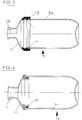
- FIG. 1 shows an evaporator piston 5 which is connected by means of a screw connection 8 to a steam guide tube 6 which is connected on the one hand to a collecting vessel 9 and on the other hand to a cooler 7.
- FIG. 2 shows the overall structure of a rotary evaporator 1, a conventional round-bottom flask 5 being shown there.
- the evaporator flask according to the invention according to FIG. 1 can be used directly instead of a conventional evaporator piston in an arrangement according to FIG.
- a stand part 2 is provided, on which a motor 3 is fastened, which drives the evaporator piston 5 via a holding and drive device 4.
- the steam guide tube 6 (FIG. 1) runs through the drive part 4, through which the steam rising from the piston 5 is guided into the cooler 7.
- the cooler 7 is fixed stationary on the stand 2 in a known manner.
- the evaporator flask 5 consists of a cylindrical cup part 5a and a cover part 5b.
- the cover part 5b is provided on the one hand with a flange 10 through which it can be fastened to the drive device 4 by means of the screw connection 8.
- the cover part 5b has a second flange 11, on which a connecting element in the form of a screw ring 12 is provided.
- the screw ring 12 engages in a corresponding thread (not shown) on the outer edge of the cup part 5a, so that the cover part 5b and cup part 5a can be firmly screwed together.
- an elastic sealing ring 13 is arranged in the screw ring 12, which is pressed together in the sealing position between the cover part 5b and the upper edge of the cup part 5a when the screw ring 12 is screwed on.
- the screw ring 12 can either in a known manner with a continuous thread or be provided with a bayonet thread or another type of arrangement for the positive connection of the cup part 5a and the lid part 5b.
- a holder 15 is fastened in the stationary steam guide tube 6 by means of a fastening device 21, which is surrounded by the steam guide tube 6 and projects into the piston 5.
- An arrangement 16 is provided on the holder 15, with which the material located in the piston 5 can be mechanically influenced. It can be seen that the holder 15 and thus the arrangement 16 remain stationary since it is attached to the stationary steam guide tube 6. Accordingly, if the piston 5 rotates during operation, there is a relative movement between the material located in the piston 5 and the arrangement 16, so that the material can be influenced mechanically.
- the arrangement 16 carries a scraper 17 which constantly brushes the inner wall of the piston 5 during operation and thus wipes off the material in the piston 5 and spreads it on the piston wall.
- a passage 18 is provided in the upper area of the arrangement 16, so that the arrangement 16 simultaneously acts as a stirrer for the material located in the piston 5.
- Figure 4 shows a modified embodiment of a piston 5 with cover part 5b and cup part 5a.
- the cover part 5b is provided with a cylindrical extension 20 which engages in the cup part 5a and supports its wall in the opening area from the inside.
- a cylindrical extension 20 which engages in the cup part 5a and supports its wall in the opening area from the inside.
Landscapes
- Chemical & Material Sciences (AREA)
- Chemical Kinetics & Catalysis (AREA)
- Health & Medical Sciences (AREA)
- Clinical Laboratory Science (AREA)
- Vaporization, Distillation, Condensation, Sublimation, And Cold Traps (AREA)
- Devices For Use In Laboratory Experiments (AREA)
Priority Applications (1)
| Application Number | Priority Date | Filing Date | Title |
|---|---|---|---|
| DE9422261U DE9422261U1 (de) | 1993-10-14 | 1994-09-15 | Verdampfer-Kolben für einen Rotationsverdampfer |
Applications Claiming Priority (2)
| Application Number | Priority Date | Filing Date | Title |
|---|---|---|---|
| DE9315698U DE9315698U1 (de) | 1993-10-14 | 1993-10-14 | Verdampfer-Kolben für einen Rotationsverdampfer |
| DE9315698U | 1993-10-14 |
Publications (2)
| Publication Number | Publication Date |
|---|---|
| EP0648519A2 true EP0648519A2 (fr) | 1995-04-19 |
| EP0648519A3 EP0648519A3 (fr) | 1995-09-06 |
Family
ID=6899432
Family Applications (1)
| Application Number | Title | Priority Date | Filing Date |
|---|---|---|---|
| EP94810533A Withdrawn EP0648519A3 (fr) | 1993-10-14 | 1994-09-15 | Alambic d'évaporation pour une évaporateur rotative. |
Country Status (4)
| Country | Link |
|---|---|
| US (2) | US5536374A (fr) |
| EP (1) | EP0648519A3 (fr) |
| JP (1) | JP3002981U (fr) |
| DE (1) | DE9315698U1 (fr) |
Cited By (1)
| Publication number | Priority date | Publication date | Assignee | Title |
|---|---|---|---|---|
| EP2962760A1 (fr) | 2014-07-01 | 2016-01-06 | Büchi Labortechnik AG | Fermeture de gobelet destiné à fermer un récipient de traitement |
Families Citing this family (21)
| Publication number | Priority date | Publication date | Assignee | Title |
|---|---|---|---|---|
| US6045588A (en) | 1997-04-29 | 2000-04-04 | Whirlpool Corporation | Non-aqueous washing apparatus and method |
| US7534304B2 (en) | 1997-04-29 | 2009-05-19 | Whirlpool Corporation | Non-aqueous washing machine and methods |
| US7513132B2 (en) | 2003-10-31 | 2009-04-07 | Whirlpool Corporation | Non-aqueous washing machine with modular construction |
| US7513004B2 (en) | 2003-10-31 | 2009-04-07 | Whirlpool Corporation | Method for fluid recovery in a semi-aqueous wash process |
| US7739891B2 (en) | 2003-10-31 | 2010-06-22 | Whirlpool Corporation | Fabric laundering apparatus adapted for using a select rinse fluid |
| US7695524B2 (en) | 2003-10-31 | 2010-04-13 | Whirlpool Corporation | Non-aqueous washing machine and methods |
| US7300468B2 (en) | 2003-10-31 | 2007-11-27 | Whirlpool Patents Company | Multifunctioning method utilizing a two phase non-aqueous extraction process |
| WO2005106105A1 (fr) | 2004-04-29 | 2005-11-10 | Unilever N.V. | Procede de nettoyage a sec |
| FR2871283B1 (fr) * | 2004-06-03 | 2006-09-22 | Tech En Milieu Ionisant Stmi S | Procede de stabilisation du mercure metallique par le soufre |
| US7966684B2 (en) | 2005-05-23 | 2011-06-28 | Whirlpool Corporation | Methods and apparatus to accelerate the drying of aqueous working fluids |
| JP5246842B2 (ja) * | 2007-10-02 | 2013-07-24 | 独立行政法人放射線医学総合研究所 | ロータリエバポレータ及びこのロータリエバポレータを備えた放射性薬剤の自動調剤装置 |
| DE102009006816A1 (de) * | 2009-01-30 | 2010-08-05 | Hans Heidolph Gmbh & Co. Kg | Rotationsverdampfer |
| DE102009006746A1 (de) * | 2009-01-30 | 2010-08-05 | Hans Heidolph Gmbh & Co. Kg | Rotationsverdampfer |
| CN102513171B (zh) * | 2011-12-20 | 2014-04-30 | 深圳市华测检测技术股份有限公司 | 可度量的旋转蒸发仪 |
| DE102013204459A1 (de) * | 2013-03-14 | 2014-09-18 | Hans Heidolph Gmbh & Co. Kg | Rotationsverdampfer |
| USD748232S1 (en) | 2013-06-17 | 2016-01-26 | Büchi Labortechnik AG | Rotary evaporator |
| DE102014107187A1 (de) * | 2014-05-21 | 2015-11-26 | Hans Heidolph Gmbh & Co. Kg | Rotationsverdampfer |
| CN107970630A (zh) * | 2018-01-02 | 2018-05-01 | 北京师范大学 | 带有电加热带的旋转蒸发装置 |
| CN109925737B (zh) * | 2019-04-23 | 2021-04-06 | 宁波巨化化工科技有限公司 | 耦合精馏设备 |
| DE102019005861B4 (de) * | 2019-08-20 | 2022-02-10 | Uwe Külz | Rotationsverdampfer |
| CN119607585B (zh) * | 2025-02-12 | 2025-05-02 | 山西润金茂环保科技股份有限公司 | 一种表面活性剂减压蒸馏反应装置 |
Family Cites Families (17)
| Publication number | Priority date | Publication date | Assignee | Title |
|---|---|---|---|---|
| FR443054A (fr) * | 1911-04-29 | 1912-09-16 | Martin Andre Rosanoff | Procédé et dispositif perfectionnés pour la distillation fractionnée |
| FR956754A (fr) * | 1944-06-13 | 1950-02-07 | ||
| NL96388C (fr) * | 1957-05-15 | |||
| US3054444A (en) * | 1959-03-09 | 1962-09-18 | Frank E Robbins | Wiper blade construction for wiped film liquid processors |
| US3138370A (en) * | 1963-03-04 | 1964-06-23 | Thermolyne Corp | Magnetic stirring device |
| FR1583466A (fr) * | 1968-06-28 | 1969-10-31 | ||
| US3837491A (en) * | 1972-11-03 | 1974-09-24 | Pollution Control Inc | Liquid purification apparatus and process |
| DE2534446A1 (de) * | 1975-08-01 | 1977-02-10 | Buechi Laboratoriumstechnik Ag | Vakuum-rotationsdampfer |
| US4024648A (en) * | 1975-10-22 | 1977-05-24 | Bender Charles E | Safety flask for freeze drying |
| DE3330764C2 (de) * | 1982-10-15 | 1994-10-27 | Yamato Scient Co Ltd | Rotationsverdampfer |
| US4790911A (en) * | 1987-03-10 | 1988-12-13 | Martin Parkinson | Solvent evaporator |
| US4913777A (en) * | 1987-12-11 | 1990-04-03 | Martin Parkinson | Solvent evaporator |
| DE59202997D1 (de) * | 1991-03-15 | 1995-08-31 | Buechi Lab Tech | Dichtungseinrichtung für einen Rotationsverdampfer. |
| TW279808B (fr) * | 1992-10-29 | 1996-07-01 | Idemitsu Kosan Co | |
| DE59407365D1 (de) * | 1993-06-11 | 1999-01-14 | Werner Lautenschlaeger | Rotationsverdampfer |
| DE4405717C1 (de) * | 1994-02-23 | 1995-06-14 | Genser Fritz | Anordnung zur Abführung und Sammlung des Destillats von Vakuumrotationsverdampfern |
| AU2002366951A1 (en) * | 2001-12-10 | 2003-07-09 | Nuvelo,Inc. | Novel nucleic acids and polypeptides |
-
1993
- 1993-10-14 DE DE9315698U patent/DE9315698U1/de not_active Expired - Lifetime
-
1994
- 1994-01-19 US US08/183,319 patent/US5536374A/en not_active Expired - Fee Related
- 1994-02-14 JP JP1994000601U patent/JP3002981U/ja not_active Expired - Lifetime
- 1994-09-15 EP EP94810533A patent/EP0648519A3/fr not_active Withdrawn
-
1996
- 1996-02-22 US US08/603,917 patent/US5759356A/en not_active Expired - Lifetime
Cited By (2)
| Publication number | Priority date | Publication date | Assignee | Title |
|---|---|---|---|---|
| EP2962760A1 (fr) | 2014-07-01 | 2016-01-06 | Büchi Labortechnik AG | Fermeture de gobelet destiné à fermer un récipient de traitement |
| WO2016000942A1 (fr) * | 2014-07-01 | 2016-01-07 | Büchi Labortechnik AG | Bouchon à bécher destiné à fermer un récipient de procédé |
Also Published As
| Publication number | Publication date |
|---|---|
| JP3002981U (ja) | 1994-10-11 |
| EP0648519A3 (fr) | 1995-09-06 |
| US5759356A (en) | 1998-06-02 |
| DE9315698U1 (de) | 1993-12-23 |
| US5536374A (en) | 1996-07-16 |
Similar Documents
| Publication | Publication Date | Title |
|---|---|---|
| EP0648519A2 (fr) | Alambic d'évaporation pour une évaporateur rotative | |
| DE202022102495U1 (de) | Bodenwaschmaschine und Reinigungssystem | |
| DE212018000003U1 (de) | Tasse mit durch Zusammendrücken angetriebenen Rühreinrichtungen | |
| DE1486813C3 (de) | Filtervorrichtung, insbesondere Druckoder Vakuumfiltervorrichtung mit einem oder mehreren Filtertellern | |
| EP0538190B1 (fr) | Dispositif d'essuyage pour machine à imprimer en creux | |
| DE2459881B2 (de) | Zahnärztliches Gerät mit einer Absaugvorrichtung | |
| DE3515711C2 (fr) | ||
| DE9301281U1 (de) | Vorrichtung zum Reinigen von Arbeitsgeräten von Malerbetrieben | |
| DE19819640A1 (de) | Reinigungsvorrichtung | |
| DE4010679C2 (de) | Reinigungsvorrichtung für Siebdruckschablonen und Zubehör | |
| DE9422261U1 (de) | Verdampfer-Kolben für einen Rotationsverdampfer | |
| EP0232835B1 (fr) | Tambour d'onguent pour la préparation de suspensions pharmaceutiques ou cosmétiques | |
| DE10030458A1 (de) | Dosiervorrichtung für flüssige oder pastöse Produkte | |
| DE2341083C2 (de) | Rührwerkaggregat | |
| DE7733655U1 (de) | Fußbodenreinigungsmaschine | |
| DE2745853C2 (de) | Farbtonmischvorrichtung | |
| DE1921717A1 (de) | Zellenlose Vakuumdrehfilter | |
| EP0277541A1 (fr) | Récipient pour stockage de produits à pomper | |
| DE102006054946A1 (de) | Vorrichtung zum Reinigen eines Behälters im Druckwerk einer Rotationsdruckmaschine | |
| DE1940644U (de) | Vorrichtung zum entsaften von citrusfruechten od. dgl. | |
| DE2121276C3 (de) | Staubabscheider | |
| EP0451448A1 (fr) | Machine à café | |
| DE3610421A1 (de) | Vorrichtung an ablassoeffnungen von oelwannen | |
| DE102024128832A1 (de) | Mischer zum Verarbeiten von pulver- grieß- und /oder granulatförmigen Stoffen und Flüssigkeiten | |
| DE462885C (de) | Mechanische Siebvorrichtung fuer Hefe |
Legal Events
| Date | Code | Title | Description |
|---|---|---|---|
| PUAI | Public reference made under article 153(3) epc to a published international application that has entered the european phase |
Free format text: ORIGINAL CODE: 0009012 |
|
| AK | Designated contracting states |
Kind code of ref document: A2 Designated state(s): CH DE FR GB LI |
|
| PUAL | Search report despatched |
Free format text: ORIGINAL CODE: 0009013 |
|
| AK | Designated contracting states |
Kind code of ref document: A3 Designated state(s): CH DE FR GB LI |
|
| 17P | Request for examination filed |
Effective date: 19960129 |
|
| 17Q | First examination report despatched |
Effective date: 19970828 |
|
| STAA | Information on the status of an ep patent application or granted ep patent |
Free format text: STATUS: THE APPLICATION IS DEEMED TO BE WITHDRAWN |
|
| 18D | Application deemed to be withdrawn |
Effective date: 19990713 |