EP0648522B1 - Appareil de coalescence du type chargé pour séparer l'huile de l'eau - Google Patents
Appareil de coalescence du type chargé pour séparer l'huile de l'eau Download PDFInfo
- Publication number
- EP0648522B1 EP0648522B1 EP94115781A EP94115781A EP0648522B1 EP 0648522 B1 EP0648522 B1 EP 0648522B1 EP 94115781 A EP94115781 A EP 94115781A EP 94115781 A EP94115781 A EP 94115781A EP 0648522 B1 EP0648522 B1 EP 0648522B1
- Authority
- EP
- European Patent Office
- Prior art keywords
- oil
- water
- electrode
- liquid
- separated
- Prior art date
- Legal status (The legal status is an assumption and is not a legal conclusion. Google has not performed a legal analysis and makes no representation as to the accuracy of the status listed.)
- Expired - Lifetime
Links
- XLYOFNOQVPJJNP-UHFFFAOYSA-N water Substances O XLYOFNOQVPJJNP-UHFFFAOYSA-N 0.000 title claims description 128
- 239000007788 liquid Substances 0.000 claims description 76
- 239000002245 particle Substances 0.000 claims description 27
- 238000009825 accumulation Methods 0.000 claims description 16
- 239000012535 impurity Substances 0.000 claims description 10
- 239000002184 metal Substances 0.000 claims description 10
- 229910052751 metal Inorganic materials 0.000 claims description 10
- 238000001914 filtration Methods 0.000 claims description 8
- 238000000034 method Methods 0.000 claims description 6
- 230000003247 decreasing effect Effects 0.000 claims description 2
- 239000003921 oil Substances 0.000 description 84
- 230000005684 electric field Effects 0.000 description 10
- 230000000694 effects Effects 0.000 description 9
- 238000000926 separation method Methods 0.000 description 7
- 239000000428 dust Substances 0.000 description 6
- 239000000839 emulsion Substances 0.000 description 6
- 230000007423 decrease Effects 0.000 description 5
- 239000000463 material Substances 0.000 description 5
- 239000012212 insulator Substances 0.000 description 4
- 238000004064 recycling Methods 0.000 description 4
- 230000005611 electricity Effects 0.000 description 3
- 230000005484 gravity Effects 0.000 description 3
- 239000000203 mixture Substances 0.000 description 3
- 239000002699 waste material Substances 0.000 description 3
- 230000033228 biological regulation Effects 0.000 description 2
- 239000000835 fiber Substances 0.000 description 2
- 238000009413 insulation Methods 0.000 description 2
- 230000002940 repellent Effects 0.000 description 2
- 239000005871 repellent Substances 0.000 description 2
- OKTJSMMVPCPJKN-UHFFFAOYSA-N Carbon Chemical compound [C] OKTJSMMVPCPJKN-UHFFFAOYSA-N 0.000 description 1
- 229920000049 Carbon (fiber) Polymers 0.000 description 1
- 230000001174 ascending effect Effects 0.000 description 1
- 230000004323 axial length Effects 0.000 description 1
- 229910052799 carbon Inorganic materials 0.000 description 1
- 239000004917 carbon fiber Substances 0.000 description 1
- 238000004140 cleaning Methods 0.000 description 1
- 239000004020 conductor Substances 0.000 description 1
- 238000005260 corrosion Methods 0.000 description 1
- 230000007797 corrosion Effects 0.000 description 1
- 238000007599 discharging Methods 0.000 description 1
- 239000012530 fluid Substances 0.000 description 1
- JEIPFZHSYJVQDO-UHFFFAOYSA-N iron(III) oxide Inorganic materials O=[Fe]O[Fe]=O JEIPFZHSYJVQDO-UHFFFAOYSA-N 0.000 description 1
- 239000010410 layer Substances 0.000 description 1
- 150000002739 metals Chemical class 0.000 description 1
- VNWKTOKETHGBQD-UHFFFAOYSA-N methane Chemical compound C VNWKTOKETHGBQD-UHFFFAOYSA-N 0.000 description 1
- 238000006386 neutralization reaction Methods 0.000 description 1
- 239000012811 non-conductive material Substances 0.000 description 1
- 230000000149 penetrating effect Effects 0.000 description 1
- 230000002093 peripheral effect Effects 0.000 description 1
- 230000003449 preventive effect Effects 0.000 description 1
- 239000010734 process oil Substances 0.000 description 1
- 238000007789 sealing Methods 0.000 description 1
- 239000002356 single layer Substances 0.000 description 1
- 239000010802 sludge Substances 0.000 description 1
- 239000007787 solid Substances 0.000 description 1
- 239000002569 water oil cream Substances 0.000 description 1
Images

Classifications
-
- B—PERFORMING OPERATIONS; TRANSPORTING
- B01—PHYSICAL OR CHEMICAL PROCESSES OR APPARATUS IN GENERAL
- B01D—SEPARATION
- B01D17/00—Separation of liquids, not provided for elsewhere, e.g. by thermal diffusion
- B01D17/02—Separation of non-miscible liquids
- B01D17/04—Breaking emulsions
- B01D17/045—Breaking emulsions with coalescers
-
- B—PERFORMING OPERATIONS; TRANSPORTING
- B01—PHYSICAL OR CHEMICAL PROCESSES OR APPARATUS IN GENERAL
- B01D—SEPARATION
- B01D17/00—Separation of liquids, not provided for elsewhere, e.g. by thermal diffusion
- B01D17/06—Separation of liquids from each other by electricity
-
- B—PERFORMING OPERATIONS; TRANSPORTING
- B03—SEPARATION OF SOLID MATERIALS USING LIQUIDS OR USING PNEUMATIC TABLES OR JIGS; MAGNETIC OR ELECTROSTATIC SEPARATION OF SOLID MATERIALS FROM SOLID MATERIALS OR FLUIDS; SEPARATION BY HIGH-VOLTAGE ELECTRIC FIELDS
- B03C—MAGNETIC OR ELECTROSTATIC SEPARATION OF SOLID MATERIALS FROM SOLID MATERIALS OR FLUIDS; SEPARATION BY HIGH-VOLTAGE ELECTRIC FIELDS
- B03C11/00—Separation by high-voltage electrical fields, not provided for in other groups of this subclass
-
- B—PERFORMING OPERATIONS; TRANSPORTING
- B03—SEPARATION OF SOLID MATERIALS USING LIQUIDS OR USING PNEUMATIC TABLES OR JIGS; MAGNETIC OR ELECTROSTATIC SEPARATION OF SOLID MATERIALS FROM SOLID MATERIALS OR FLUIDS; SEPARATION BY HIGH-VOLTAGE ELECTRIC FIELDS
- B03C—MAGNETIC OR ELECTROSTATIC SEPARATION OF SOLID MATERIALS FROM SOLID MATERIALS OR FLUIDS; SEPARATION BY HIGH-VOLTAGE ELECTRIC FIELDS
- B03C2201/00—Details of magnetic or electrostatic separation
- B03C2201/02—Electrostatic separation of liquids from liquids
-
- C—CHEMISTRY; METALLURGY
- C02—TREATMENT OF WATER, WASTE WATER, SEWAGE, OR SLUDGE
- C02F—TREATMENT OF WATER, WASTE WATER, SEWAGE, OR SLUDGE
- C02F2201/00—Apparatus for treatment of water, waste water or sewage
- C02F2201/002—Construction details of the apparatus
- C02F2201/003—Coaxial constructions, e.g. a cartridge located coaxially within another
-
- Y—GENERAL TAGGING OF NEW TECHNOLOGICAL DEVELOPMENTS; GENERAL TAGGING OF CROSS-SECTIONAL TECHNOLOGIES SPANNING OVER SEVERAL SECTIONS OF THE IPC; TECHNICAL SUBJECTS COVERED BY FORMER USPC CROSS-REFERENCE ART COLLECTIONS [XRACs] AND DIGESTS
- Y10—TECHNICAL SUBJECTS COVERED BY FORMER USPC
- Y10S—TECHNICAL SUBJECTS COVERED BY FORMER USPC CROSS-REFERENCE ART COLLECTIONS [XRACs] AND DIGESTS
- Y10S210/00—Liquid purification or separation
- Y10S210/05—Coalescer
Definitions
- the present invention relates to a charged coalescer type oil-water separating apparatus which efficiently separates water from water-containing oil or oil from oil-containing water to enable their recycling, and which contributes to not only saying of resources and energy but also cleaning of the earth environment by reducing waste oil and liquids.
- coalescer type oil-water separating apparatus uses a coalescer type filter element in which filtering materials are different in mesh size and are layered such that meshes become finer in a step-like manner toward the downstream side in the fluid passing direction.
- the most general form of this type of oil-water separating apparatus is as follows. A cylindrical coalescer type filter element is disposed at the center of a container, and a pressurized liquid to be processed is introduced into the container from the outside and passed through the filter element from its outside to inside. While the liquid is passed through the filter element, oil particles are interrupted by meshes that become finer in a step-like manner in the liquid passing direction, and caused to go up. Water thus separated is extracted from the axial portion of the filter element.
- a cylindrical charge electrode made of a perforated metal plate is disposed outside the filter element so as to contact with its outer surface, and a voltage that can lower or eliminate the zeta potential of impurity particles in a liquid being processed is applied between the cylindrical charge electrode and the outer cylinder grounding electrode and between the cylindrical charge electrode and the central cylinder electrode.
- a pressurized liquid to be processed that has been introduced into the container from the outside is first passed through an oil-water separating space formed between the cylindrical charge electrode and the outer cylinder grounding electrode, in which space oil particles cohere due to the charge effect and oil goes up. i.e., separated, due to the difference in specific gravity. Then, the separated water is passed through the filter element from its outer surface to its axial portion, and a filtered liquid is discharged from the filter axial portion,
- the oil-water separating apparatus using the coalescer type filter element in which the oil-water separation relies on only the physical operation, i.e., the interruption of oil particles by meshes of the filter, has a limitation in the size of separable oil particles.
- filter meshes need to have a very small size of less than 1 micron. Since such a filter tends to clog up early due to inclusion of dust or oil having a high viscosity, the filter element needs to be replaced at a high frequency. That is, in the conventional coalescer type oil-water separating apparatus, the running cost inevitably increases to obtain a higher accuracy.
- US-A-3 876 544 discloses an electrogalvanic filter cell.
- the filter cell is comprised of a central tubular perforated core of metal, about which is wrapped at least one layer or fibrous bed of metal fibers. Different metals are wound around a core for the purpose of generating an electrogalvanic potential, i.e. to create an electrogalvanic cell when a water-oil emulsion is introduced into the filter cell.
- US-A-4 919 777 discloses an electrostatic/mechanical emulsion treating method and apparatus.
- CA-A- 963 400 relates to a combination filter and a water separator for use in the separation of water from oil.
- the combination filter and water separator comprises a cylindrically shaped baffle which is mounted in the filter chamber between the coalescer filter element and the separator filter element.
- the baffle is disposed closer to the coalescer filter element and to the separator element and, as a result, the velocity of oil travelling downwardly in the annular chamber is substantially greater than that of the oil travelling upwardly in the annular chamber. This change in velocity assists in the separation of the water particles from the oil and large particles of water will settle to the bottom of a chamber after travelling downwardly to the annular chamber.
- the present invention has been made in view of the above circumstances, and has an object of providing a charged coalescer type oil-water separating apparatus which not only can separate, by a single-unit apparatus with high accuracy, oil and water from such subject liquids as a mixture of oil and water in the form of emulsion that are hardly separated by the conventional apparatuses, but also enables reuse of both water and oil that are separated and collected.
- the present invention which has been made based on the above conceptions, has the following constitution.
- a charged coalescer type oil-water separating apparatus comprises:
- the charged coalescer type oil-water separating apparatus having the above constitution operates in the following manner.
- a pressurized subject liquid is introduced by a pump or the like through the one open end of the central cylinder electrode.
- the pressurized subject liquid introduced into the central cylinder electrode enters the coalescer type filter element through the liquid passing holes and the inner surface of the filter element, passes through the filter toward its outer surface, and goes out of the filter through the holes of the cylindrical charge electrode disposed outside the filter surface.
- the primary processed liquid discharged outside of the filter is introduced into the oil-water separating space formed between the filter and the outer cylinder grounding electrode, to which the electric field is applied and in which the bypass cylinder electrode is disposed to elongate the liquid passing path.
- the primary processed liquid is already in such a state that impurity particles have been removed and oil particles and water molecules have been separated from each other. While the primary processed liquid passes through the oil-water separating space, oil particles and water molecules further cohere to become coarser under the influence of the electric field. Then, oil goes up due to the difference in specific gravity to be accumulated in the separated oil accumulation space, and is discharged outside of the container through the separated oil outlet. On the other hand, water goes down to be accumulated in the separated water accumulation space, and is discharged outside of the container through the separated water outlet. Since the separated oil and water thus collected are clean, they are suitable for recycling.
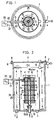
- An apparatus shown in Figs. 1 and 2 is directed to a subject liquid that is water containing a small amount of oil (hereinafter called oil-containing water).
- an apparatus shown in Figs. 5 and 6 is directed to a subject liquid that is oil containing a small amount of water (hereinafter called water-containing oil).
- water-containing oil a subject liquid that is oil containing a small amount of water
- reference numeral 1 denotes an outer cylinder grounding electrode also serving as a main body container, which is a cylinder having an open top and a closed bottom. Its side wall is formed with, at an upper position, a separated oil outlet 2 that is equipped with an electromagnetic valve 4.
- the bottom plate is formed with a drain 3 for discharging dust, sludge, etc. deposited in the container when necessary. Further, the bottom plate is formed with a separated water outlet 5 at a peripheral position.
- the outer cylinder grounding electrode 1 is further formed with a flange 6 around the top edge.
- the top opening of the outer cylinder grounding electrode 1 is covered with a lid 7, which is fixed to the flange 6 with bolts 8 that penetrate through the flange 6.
- An oil-water boundary detecting sensor 9 is suspended from the lid 7 toward the inside of the container.
- a central cylinder electrode 11 having a plurality of liquid passing holes 10 in its cylindrical wall and given the same potential as the outer cylinder grounding electrode 1 is disposed at the center (in the radial direction) of the outer cylinder grounding electrode 1.
- the bottom end of the central cylinder electrode 11 penetrates through the bottom plate of the outer cylinder grounding electrode 1 so as to project outside of the container, and the open bottom end of the projecting portion serves as an inlet 12 of a pressurized subject liquid.
- a coalescer type filter element 13 (hereinafter simply called a filter 13) is disposed outside the central cylinder electrode 11 such that the inner surface of the filter element 13 is in close proximity to or in contact with the central cylinder electrode 11.
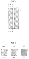
- the filter 13 is a layered body made of paper or fiber in which the mesh size decreases in a step-like manner from the inside to outside in the radial direction. While non-conductive materials are generally used as the filter material, conductive materials such as active carbon and carbon fiber may be used to improve the charge effect of the filter 13. Since this embodiment is directed to oil-containing water, an oil repellent material is used as the filter material so that oil hardly remains in the filter.
- a cylindrical charge electrode 14 made of a perforated metal plate or a mesh-like metal body is disposed outside the cylindrical surface of the filter 13 so as to contact with it.
- a predetermined voltage is applied between the cylindrical charge electrode 14 and the outer cylinder grounding electrode 1 and between the cylindrical charge electrode 14 and the central cylinder electrode 11.
- the filter 13 is detachable, and is fixed to a predetermined place in the container by being held between a filter receiving insulator 15 and a filter pressing insulator 16.
- reference numeral 17 denotes a filter fastening screw
- 18 and 19 represent O-rings for sealing.
- a grounding line 21 led from a power supply 20 that is installed outside the container is connected to the outer cylinder grounding electrode 1, and a charge line 22 that is inserted into an insulator 23 penetrating through the outer cylinder grounding electrode 1 is connected to the cylindrical charge electrode 14.
- the application voltage is selected so as to be able to lower or eliminate the zeta potential of impurity particles contained in a liquid.
- This voltage is selected in accordance with the kind of subject liquid. In general, the voltage is set lower when the subject liquid is a water soluble one such as oil-containing water, because it is low in insulation performance. Further, a DC voltage is not employed to avoid electrolytic corrosion. On the other hand, the voltage is set higher when the subject liquid is not a water soluble one such as water-containing oil, because it is high in insulation performance. In this embodiment, which is directed to oil-containing water, an AC voltage of 0.5 to 30 V/cm or an AC voltage having a high-frequency component is employed.
- An oil-water separating space 24 is formed between the cylindrical charge electrode 14 and the outer cylinder grounding electrode 1.
- a bypass cylinder electrode 25 is erected from the bottom plate of the outer cylinder grounding electrode 1 at an intermediate position in the radial direction in the oil-water separating space 24 so that the top end is spaced from the lid 7.
- the bypass cylinder electrode 25 serves to elongate the path length of a liquid that passes through the oil-water separating space 24. More specifically, the space inside the bypass cylinder electrode 25 is an ascending space and the space outside the electrode 25 is a descending space.
- the illustrated bypass cylinder electrode 25 completely prevents a liquid from passing through it, its upper half may be replaced by a perforated plate to control the amount of passing liquid.
- the upper portion of the inside space of the main body container is made a separated oil accumulation space that communicates with the separated oil outlet 2.
- the lower portion of the inside space serves as a separated water accumulation space that communicates with the separated water outlet 5.
- the charged coalescer type oil-water separating apparatus having the above configuration operates in the following manner. As indicated by solid arrows in the figures, a pressurized subject liquid is introduced by a pump from the outside of the container to the internal space of the central cylinder electrode 11. Then, the liquid is passed through the filter 13 from its inside to outside to simultaneously effect filtration and preliminary cohesion, to thereby produce a primary processed liquid, which enters the oil-water separating space 24.
- the primary processed liquid first flows upward and then downward in the oil-water separating space 24, in which process oil particles further cohere to become coarser. During this process, while separated oil goes up as indicated by dashed arrows in Fig. 2, and separated water goes dawn as indicated by chain lines. The separated oil and water are collected through the separated oil outlet 2 and the separated water outlet 5.
- the filter 13 While the subject liquid passes through the filter 13 under an electric field, i.e., passes through its fine holes whose sizes decrease in a step-like manner toward the downstream side in the subject liquid passing direction, oil and water are separated from each other by emulsion breaking and, at the same time, impurity particles such as dust are removed from the subject liquid.
- the filter 13 there occur at the same time the physical filtering operation by the meshes and the charge-induced phenomenon that particles cohere to become coarser.
- the primary processed liquid discharged outside of the filter 13 is already in such a state that impurity particles have been removed and oil particles and water molecules have been separated from each other. While the primary processed liquid passes through the oil-water separating space 24 to which an electric field is applied, oil particles further cohere to become coarser under the influence of the electric field. Then, oil goes up due to the difference in specific gravity to be accumulated in the separated oil accumulation space, and is discharged outside of the container through the separated oil outlet 2. On the other hand, water goes down to be accumulated in the separated water accumulation space, and is discharged outside of the container through the separated water outlet 5. The accumulation amount of the separated oil is always monitored by the boundary detecting sensor 9. When the accumulation amount has reached a predetermined level, the electromagnetic valve 4 is opened to discharge the oil.
- Figs. 5 and 6 show an oil-water separating apparatus directed to a subject liquid of water-containing oil.
- a bypass cylinder electrode 25a is suspended downward with its top end contacted with a filter pressing insulator 16a that contacts with the lid 7.
- a gap is provided between the bottom end of the bypass cylinder electrode 25a and the bottom plate of the outer cylinder grounding electrode 1.
- An oil-water boundary detecting sensor 9a is erected from the bottom plate of the outer cylinder grounding electrode 1, and an electromagnetic valve 4a is attached to the separated water outlet 5.
- a water repellent filter material is used to prevent water from remaining in the filter.
- an application of voltage is a DC or AC voltage of 0.5 to 200 V/cm, a DC voltage and an AC voltage superimposed an each other, or one of these types of voltages further having a high-frequency component.
- the inside of the container is mostly filled with oil, and separated water is accumulated in the bottom portion of the container.
- a primary processed liquid that has passed through the filter 13 from its inside to outside enters an oil-water separating space 24a, where the primary processed liquid first flaws downward to facilitate fail and accumulation of separated water, and then flows upward to allow separated oil to go up.
- the amount of water accumulated in the container bottom portion is always monitored by the boundary detecting sensor 9a.
- the electromagnetic valve is opened to discharge the water.
- a coalescer type filter element incorporated in the test apparatus had an outside diameter of 62 ⁇ mm, an axial length of 125 mm, and a minimum mesh size ( on the outer surface side) of 2 ⁇ m.
- a liquid to be processed as a test subject was prepared such that warm water at 50°C of 40 liters was mixed with rust preventive oil (known as hardest to be separated from water) of 0.8 liter (that is, the oil content was 2%), and a mixture was agitated and then emulsified.
- a pump for supplying the subject liquid to the test apparatus provided a flow rate of 2.5 liters/min, and the subject liquid of 40.8 liters took 16 minutes to pass, once, through the test apparatus, i.e., charged coalescer type oil-water separating apparatus.
- the subject liquid was supplied to the test apparatus, and subjected to oil-water separation. Separated water was returned to the test apparatus through a recycling path. It was measured how the oil content of the subject liquid in a tank of the test apparatus and the oil content at an outlet of the apparatus vary with the number of passages through the test apparatus, specifically, one passage, three passages and five passages.
- an electric field is applied to the coalescer type filter element in which the mesh size decreases in a step- like manner toward the outside. Further, a subject liquid is passed through the filter from its inside to outside, and a primary processed liquid discharged from the filter is introduced into the oil-water separating space that is provided outside the cylindrical outer surface of the filter. While the primary processed liquid passes through the oil-water separating space which has a long path and to which an electric field is applied, rise of separated oil and fall of separated water are facilitated. As a result, the oil-water separation of such subject liquids as a mixture of oil and water in the form of emulsion, which is hardly performed by the conventional apparatuses, can be performed efficiently with high accuracy.
- the separated oil and water discharged from the apparatus of the invention are clean and suitable for recycling, because they have been filtered.
- the apparatus since the main part of the apparatus of the invention is accommodated, as a single unit, in a single container and all the processing is performed in the single container, the apparatus is compact and can be handled easily.
Landscapes
- Physics & Mathematics (AREA)
- Thermal Sciences (AREA)
- Chemical & Material Sciences (AREA)
- Chemical Kinetics & Catalysis (AREA)
- Electrostatic Separation (AREA)
- Water Treatment By Electricity Or Magnetism (AREA)
Claims (2)
- Appareil de séparation huile-eau du type dispositif de coalescence chargé, comprenant :une électrode cylindrique extérieure (1) de mise à la masse servant aussi de récipient principal ;une électrode cylindrique centrale (11) prévue à l'intérieur de l'électrode cylindrique extérieure (1) de mise à la masse, soumise au même potentiel que l'électrode cylindrique extérieure (1) de mise à la masse, et ayant une pluralité d'orifices (10) de passage d'un liquide et une extrémité ouverte (12) servant d'entrée pour un liquide pressurisé à traiter ;un élément formant filtre (13), cylindrique, du type à coalescence, intercalé de manière amovible entre l'électrode cylindrique extérieure (1) de mise à la masse et l'électrode cylindrique centrale (11), une dimension des mailles de l'élément formant filtre (13) diminuant par échelon vers l'extérieur de l'élément formant filtre (13) suivant la direction radiale de ce dernier, une surface cylindrique intérieure de l'élément formant filtre (13) étant en contact avec l'électrode cylindrique centrale (11) ou à proximité étroite de cette dernière ;un espace de séparation (24) de l'huile et de l'eau, prévu entre l'élément formant filtre (13) et l'électrode cylindrique extérieure (1) de mise à la masse, une partie supérieure et une partie inférieure de l'espace de séparation (24, 24a) de l'huile et de l'eau servant, respectivement, d'espace d'accumulation de l'huile séparée en communication avec une sortie (2) de l'huile séparée et d'espace d'accumulation de l'eau séparée en communication avec une sortie (5) de l'eau séparée ;une électrode cylindrique de charge (14) formée d'une plaque métallique perforée ou d'un corps métallique en forme de treillis et placée à l'extérieur de l'élément formant filtre (13) de manière à être en contact avec, ou à proximité étroite de la surface cylindrique extérieure de l'élément formant filtre (13) ; etune électrode cylindrique de dérivation (25, 25a) placée dans l'espace de séparation de l'huile et de l'eau (24, 24a) de manière à être concentrique avec l'électrode cylindrique extérieure (1) de mise à la masse pour allonger le trajet de passage de liquide ;
dans lequel une tension assez élevée pour abaisser ou éliminer un potentiel zêta de particules d'impuretés dans le liquide à traiter est appliquée entre l'électrode cylindrique extérieure (1) de mise à la masse et l'électrode cylindrique de charge (14), et entre l'électrode cylindrique centrale (11) et l'électrode cylindrique de charge (14) ; et
dans lequel le liquide pressurisé à traiter est introduit par une pompe, de l'extérieur du récipient dans un espace interne de l'électrode cylindrique centrale (11), et amené à traverser l'élément formant filtre de l'intérieur de celui-ci vers l'extérieur pour former un liquide traité primaire qui a été soumis à une filtration et à une première cohésion, lequel liquide traité primaire est introduit dans l'espace de séparation de l'huile et de l'eau (24, 24a), à l'intérieur duquel l'huile et l'eau séparées s'accumulent dans les espaces respectifs d'accumulation au cours d'un procédé pendant lequel le liquide traité primaire s'écoule vers le haut et le bas, et l'huile ainsi que l'eau accumulées séparées sont finalement déchargées du récipient. - Procédé pour séparer de l'huile et de l'eau au moyen d'un appareil selon la revendication 1.
Applications Claiming Priority (2)
| Application Number | Priority Date | Filing Date | Title |
|---|---|---|---|
| JP251420/93 | 1993-10-07 | ||
| JP25142093A JPH07106283B2 (ja) | 1993-10-07 | 1993-10-07 | 荷電コアレッサー型油水分離装置 |
Publications (2)
| Publication Number | Publication Date |
|---|---|
| EP0648522A1 EP0648522A1 (fr) | 1995-04-19 |
| EP0648522B1 true EP0648522B1 (fr) | 1998-05-20 |
Family
ID=17222590
Family Applications (1)
| Application Number | Title | Priority Date | Filing Date |
|---|---|---|---|
| EP94115781A Expired - Lifetime EP0648522B1 (fr) | 1993-10-07 | 1994-10-06 | Appareil de coalescence du type chargé pour séparer l'huile de l'eau |
Country Status (4)
| Country | Link |
|---|---|
| US (1) | US5468385A (fr) |
| EP (1) | EP0648522B1 (fr) |
| JP (1) | JPH07106283B2 (fr) |
| DE (1) | DE69410384T2 (fr) |
Families Citing this family (34)
| Publication number | Priority date | Publication date | Assignee | Title |
|---|---|---|---|---|
| CN1125909A (zh) * | 1994-03-31 | 1996-07-03 | 杉浦荣市 | 清洗装置及适用于该清洗装置的分离装置及过滤装置 |
| JP2664877B2 (ja) * | 1994-10-13 | 1997-10-22 | 榮市 杉浦 | 油水分離装置 |
| US5554301A (en) * | 1995-05-08 | 1996-09-10 | Universal Environmental Technologies, Inc. | Water clarification system |
| US5849100A (en) * | 1995-05-15 | 1998-12-15 | Bowden Industries | Method for cleaning oily objects |
| US6068779A (en) * | 1996-01-29 | 2000-05-30 | Spintek Systems, Inc. | Enhanced liquid mixture separation system |
| US6200489B1 (en) * | 1996-01-29 | 2001-03-13 | Spintek Systems, Inc. | Liquid mixture separation system |
| US6106592A (en) * | 1998-03-17 | 2000-08-22 | Monsanto Company | Wet electrostatic filtration process and apparatus for cleaning a gas stream |
| JP2002224503A (ja) * | 2001-02-02 | 2002-08-13 | Wako Industrial Co Ltd | 流体・水分離装置 |
| GB2377397A (en) * | 2001-07-12 | 2003-01-15 | Mojtaba Ghadiri | Separating components of liquid/liquid emulsion using electrostatic force |
| US6859983B2 (en) * | 2001-09-20 | 2005-03-01 | Polymer Group, Inc. | Camouflage material |
| JP4289352B2 (ja) * | 2003-06-10 | 2009-07-01 | 有限会社ゼオテック研究所 | 廃液濾過システム車 |
| US20080028873A1 (en) * | 2006-08-03 | 2008-02-07 | Yi Zhao Yao | Dispersed spray extraction particulate measurement method |
| CA2582585A1 (fr) * | 2007-03-26 | 2008-09-26 | Separatech Canada Inc. | Separateur a cartouche pour liquides immiscibles |
| WO2010028117A1 (fr) * | 2008-09-03 | 2010-03-11 | Cummins Filtration Ip Inc. | Milieu coalesceur à chemise d'air, présentant une performance améliorée |
| JP5425431B2 (ja) * | 2008-09-10 | 2014-02-26 | 株式会社ゼオテック | アルミダイカスト成型機の離型剤廃液の再生方法、再生システム及び再生システム車輌 |
| US8517185B2 (en) * | 2008-10-08 | 2013-08-27 | Cummins Filtration Ip, Inc. | Two stage fuel water separator and particulate filter utilizing pleated nanofiber filter material |
| US8590712B2 (en) | 2008-10-08 | 2013-11-26 | Cummins Filtration Ip Inc. | Modular filter elements for use in a filter-in-filter cartridge |
| US8360251B2 (en) | 2008-10-08 | 2013-01-29 | Cummins Filtration Ip, Inc. | Multi-layer coalescing media having a high porosity interior layer and uses thereof |
| US8414756B2 (en) * | 2008-10-30 | 2013-04-09 | National Tank Company | Removal of glycerin from biodiesel using an electrostatic process |
| WO2010132785A2 (fr) | 2009-05-15 | 2010-11-18 | Cummins Filtration Ip, Inc. | Coalesceur de surface |
| BR112012007945A2 (pt) | 2009-11-16 | 2016-03-22 | Cummins Filtration Ip Inc | sistemas coalescentes |
| WO2011150043A2 (fr) * | 2010-05-28 | 2011-12-01 | Board Of Supervisors Of Louisiana State University And Agricultural And Mechanical College | Séparateur pétrole - eau |
| DE112011102094B4 (de) | 2010-06-22 | 2024-12-19 | Cummins Filtration Ip, Inc. | Eine Filterpatrone und Verwendung einer Filterpatrone |
| US9795972B2 (en) * | 2012-08-07 | 2017-10-24 | Cameron International Corporation | High temperature high pressure electrostatic treater |
| US10058808B2 (en) | 2012-10-22 | 2018-08-28 | Cummins Filtration Ip, Inc. | Composite filter media utilizing bicomponent fibers |
| BR112016007799B1 (pt) | 2013-10-16 | 2021-09-14 | Cummins Filtration Ip, Inc | Conjunto e elemento de filtro com recurso eletrônico de detecção de filtro para sistemas de filtração de líquido |
| CN121222126A (zh) | 2016-07-19 | 2025-12-30 | 安美世滤清系统知识产权公司 | 穿孔层聚结器 |
| US11819782B2 (en) | 2017-04-25 | 2023-11-21 | The University Of Akron | Electrowetting coalescence device with porous layers |
| AU2021354361B2 (en) | 2020-09-29 | 2024-01-18 | Mitsubishi Kakoki Kaisha, Ltd. | Filtration device, and filtration system |
| WO2022091363A1 (fr) * | 2020-10-30 | 2022-05-05 | 三菱化工機株式会社 | Système de filtration et dispositif de filtration |
| WO2022091364A1 (fr) * | 2020-10-30 | 2022-05-05 | 三菱化工機株式会社 | Dispositif de filtration |
| JP7474866B2 (ja) * | 2020-11-26 | 2024-04-25 | 三菱化工機株式会社 | ろ過装置 |
| JP7308368B2 (ja) * | 2021-01-14 | 2023-07-13 | 三菱化工機株式会社 | ろ過装置 |
| US20250128190A1 (en) * | 2022-02-11 | 2025-04-24 | The University Of Akron | Electrowetting coalescence device for use with organic process fluids |
Family Cites Families (16)
| Publication number | Priority date | Publication date | Assignee | Title |
|---|---|---|---|---|
| US2651414A (en) * | 1948-04-17 | 1953-09-08 | Lawson Products Corp | Hydrocarbon separator apparatus and separator element |
| US3876594A (en) * | 1970-10-20 | 1975-04-08 | Ceskoslovenska Akademie Ved | Method for producing of articles from hydrophilic polymers appropriate for repeated or long-term contact with living tissue or mucous membrane |
| JPS5128938B1 (fr) * | 1970-11-26 | 1976-08-23 | ||
| CA963400A (en) * | 1971-09-29 | 1975-02-25 | Aircraft Appliances And Equipment Limited | Combination filter and water separator |
| US3800945A (en) * | 1971-11-26 | 1974-04-02 | Cata Sep Inc | Cell having catalytic action for coalescing oil droplets |
| US3859195A (en) * | 1972-09-20 | 1975-01-07 | Du Pont | Apparatus for electrochemical processing |
| US3948767A (en) * | 1974-02-06 | 1976-04-06 | Chapman Willis F | Method and apparatus for separating oil from aqueous liquids |
| DE2424091C3 (de) * | 1974-05-17 | 1980-11-27 | Sachs Systemtechnik Gmbh, 8720 Schweinfurt | Verfahren zur anodischen Oxidation organischer Belastungsstoffe im Wasser in einer Wirbelschicht aus leitfähigem Adsorbens |
| US4159235A (en) * | 1976-11-22 | 1979-06-26 | Gotzelmann Kg | Method and apparatus for treating metal containing waste water |
| GB1600371A (en) * | 1978-01-31 | 1981-10-14 | Whatman Reeve Angel Ltd | Oil coalescing filter cartridge |
| JPS57106490U (fr) * | 1980-12-23 | 1982-06-30 | ||
| JPS5895507A (ja) * | 1981-11-25 | 1983-06-07 | Nitto Electric Ind Co Ltd | 溶液分離装置 |
| JPS5942014A (ja) * | 1982-08-31 | 1984-03-08 | Nippon Soken Inc | 静電ろ過器用ろ過体 |
| JPS62216616A (ja) * | 1986-03-18 | 1987-09-24 | Kimihiko Okanoe | 液体濾過装置 |
| US4919777A (en) * | 1987-04-07 | 1990-04-24 | Bull Hendrix R | Electrostatic/mechanical emulsion treating method and apparatus |
| US5244550A (en) * | 1991-02-25 | 1993-09-14 | Toyota Jidosha Kabushiki Kaisha | Two liquid separating methods and apparatuses for implementing them |
-
1993
- 1993-10-07 JP JP25142093A patent/JPH07106283B2/ja not_active Expired - Lifetime
-
1994
- 1994-10-05 US US08/318,101 patent/US5468385A/en not_active Expired - Lifetime
- 1994-10-06 DE DE69410384T patent/DE69410384T2/de not_active Expired - Fee Related
- 1994-10-06 EP EP94115781A patent/EP0648522B1/fr not_active Expired - Lifetime
Also Published As
| Publication number | Publication date |
|---|---|
| JPH07106283B2 (ja) | 1995-11-15 |
| JPH07100302A (ja) | 1995-04-18 |
| EP0648522A1 (fr) | 1995-04-19 |
| DE69410384T2 (de) | 1999-01-21 |
| DE69410384D1 (de) | 1998-06-25 |
| US5468385A (en) | 1995-11-21 |
Similar Documents
| Publication | Publication Date | Title |
|---|---|---|
| EP0648522B1 (fr) | Appareil de coalescence du type chargé pour séparer l'huile de l'eau | |
| US5236585A (en) | Oil accumulator | |
| JP3405278B2 (ja) | 荷電凝集フイルターコアレッサー型油水分離装置およびシステム | |
| FI75139C (fi) | Foerfarande och apparatur foer avskiljning av olja fraon vatten. | |
| US5244550A (en) | Two liquid separating methods and apparatuses for implementing them | |
| KR890005261B1 (ko) | 액체여과장치 | |
| JP2591495B2 (ja) | 超精密濾過システム及び当該システムを用いた超精密濾過方法 | |
| DE2837491A1 (de) | Kompakte vorrichtung zur kontinuierlichen behandlung eines emulgierte kohlenwasserstoffe enthaltenden abwassers | |
| GB2177625A (en) | Fluid filtering apparatus | |
| US4372837A (en) | Radial flow electrofilter | |
| CA2229224C (fr) | Dispositif et methode permettant de retirer de la matiere particulaire de liquides non conducteurs | |
| US4302310A (en) | Radial flow electrofilter | |
| CA2243142C (fr) | Appareil sans filtre multi-etage et methode pour la separation de fluides immiscibles | |
| CN214327319U (zh) | 用于油水分离预处理的滤芯及组件和油水分离装置 | |
| SU1258313A3 (ru) | Устройство дл очистки маслосодержащих сточных вод | |
| CN218130109U (zh) | 一种用于油水分离精处理的滤芯及其应用的组件和油水分离装置 | |
| JPH0353682Y2 (fr) | ||
| EP0105964A1 (fr) | Procédé pour la séparation continue de matière polluante à partir d'un fluide porteur | |
| CN114159838A (zh) | 一种油水分离精处理装置及油水分离精处理方法 | |
| SU1301444A1 (ru) | Фильтр-водоотделитель | |
| CN119774800B (zh) | 一种含焦油废水的处理系统及处理方法 | |
| CN114162899A (zh) | 一种油水分离预处理装置及油水分离预处理方法 | |
| CN213357164U (zh) | 一种一体化反应分离净化装置 | |
| CA1147290A (fr) | Appareil pour la purification electrochimique de liquides contamines | |
| CN220745484U (zh) | 一种工业含油废水聚结分离装置 |
Legal Events
| Date | Code | Title | Description |
|---|---|---|---|
| PUAI | Public reference made under article 153(3) epc to a published international application that has entered the european phase |
Free format text: ORIGINAL CODE: 0009012 |
|
| AK | Designated contracting states |
Kind code of ref document: A1 Designated state(s): DE |
|
| 17P | Request for examination filed |
Effective date: 19950926 |
|
| 17Q | First examination report despatched |
Effective date: 19951220 |
|
| GRAG | Despatch of communication of intention to grant |
Free format text: ORIGINAL CODE: EPIDOS AGRA |
|
| GRAG | Despatch of communication of intention to grant |
Free format text: ORIGINAL CODE: EPIDOS AGRA |
|
| GRAG | Despatch of communication of intention to grant |
Free format text: ORIGINAL CODE: EPIDOS AGRA |
|
| GRAH | Despatch of communication of intention to grant a patent |
Free format text: ORIGINAL CODE: EPIDOS IGRA |
|
| GRAH | Despatch of communication of intention to grant a patent |
Free format text: ORIGINAL CODE: EPIDOS IGRA |
|
| GRAA | (expected) grant |
Free format text: ORIGINAL CODE: 0009210 |
|
| AK | Designated contracting states |
Kind code of ref document: B1 Designated state(s): DE |
|
| REF | Corresponds to: |
Ref document number: 69410384 Country of ref document: DE Date of ref document: 19980625 |
|
| PLBE | No opposition filed within time limit |
Free format text: ORIGINAL CODE: 0009261 |
|
| STAA | Information on the status of an ep patent application or granted ep patent |
Free format text: STATUS: NO OPPOSITION FILED WITHIN TIME LIMIT |
|
| 26N | No opposition filed | ||
| PGFP | Annual fee paid to national office [announced via postgrant information from national office to epo] |
Ref country code: DE Payment date: 20051129 Year of fee payment: 12 |
|
| PG25 | Lapsed in a contracting state [announced via postgrant information from national office to epo] |
Ref country code: DE Free format text: LAPSE BECAUSE OF NON-PAYMENT OF DUE FEES Effective date: 20070501 |