EP0648635B1 - Système d'entraínement hybride pour véhicules, notamment pour usage urbain - Google Patents
Système d'entraínement hybride pour véhicules, notamment pour usage urbain Download PDFInfo
- Publication number
- EP0648635B1 EP0648635B1 EP93830414A EP93830414A EP0648635B1 EP 0648635 B1 EP0648635 B1 EP 0648635B1 EP 93830414 A EP93830414 A EP 93830414A EP 93830414 A EP93830414 A EP 93830414A EP 0648635 B1 EP0648635 B1 EP 0648635B1
- Authority
- EP
- European Patent Office
- Prior art keywords
- heat engine
- electric motor
- propulsion system
- electric
- epicyclic gearing
- Prior art date
- Legal status (The legal status is an assumption and is not a legal conclusion. Google has not performed a legal analysis and makes no representation as to the accuracy of the status listed.)
- Expired - Lifetime
Links
Images
Classifications
-
- B—PERFORMING OPERATIONS; TRANSPORTING
- B60—VEHICLES IN GENERAL
- B60W—CONJOINT CONTROL OF VEHICLE SUB-UNITS OF DIFFERENT TYPE OR DIFFERENT FUNCTION; CONTROL SYSTEMS SPECIALLY ADAPTED FOR HYBRID VEHICLES; ROAD VEHICLE DRIVE CONTROL SYSTEMS FOR PURPOSES NOT RELATED TO THE CONTROL OF A PARTICULAR SUB-UNIT
- B60W20/00—Control systems specially adapted for hybrid vehicles
-
- B—PERFORMING OPERATIONS; TRANSPORTING
- B60—VEHICLES IN GENERAL
- B60K—ARRANGEMENT OR MOUNTING OF PROPULSION UNITS OR OF TRANSMISSIONS IN VEHICLES; ARRANGEMENT OR MOUNTING OF PLURAL DIVERSE PRIME-MOVERS IN VEHICLES; AUXILIARY DRIVES FOR VEHICLES; INSTRUMENTATION OR DASHBOARDS FOR VEHICLES; ARRANGEMENTS IN CONNECTION WITH COOLING, AIR INTAKE, GAS EXHAUST OR FUEL SUPPLY OF PROPULSION UNITS IN VEHICLES
- B60K6/00—Arrangement or mounting of plural diverse prime-movers for mutual or common propulsion, e.g. hybrid propulsion systems comprising electric motors and internal combustion engines
- B60K6/20—Arrangement or mounting of plural diverse prime-movers for mutual or common propulsion, e.g. hybrid propulsion systems comprising electric motors and internal combustion engines the prime-movers consisting of electric motors and internal combustion engines, e.g. HEVs
- B60K6/22—Arrangement or mounting of plural diverse prime-movers for mutual or common propulsion, e.g. hybrid propulsion systems comprising electric motors and internal combustion engines the prime-movers consisting of electric motors and internal combustion engines, e.g. HEVs characterised by apparatus, components or means specially adapted for HEVs
- B60K6/38—Arrangement or mounting of plural diverse prime-movers for mutual or common propulsion, e.g. hybrid propulsion systems comprising electric motors and internal combustion engines the prime-movers consisting of electric motors and internal combustion engines, e.g. HEVs characterised by apparatus, components or means specially adapted for HEVs characterised by the driveline clutches
- B60K6/383—One-way clutches or freewheel devices
-
- B—PERFORMING OPERATIONS; TRANSPORTING
- B60—VEHICLES IN GENERAL
- B60K—ARRANGEMENT OR MOUNTING OF PROPULSION UNITS OR OF TRANSMISSIONS IN VEHICLES; ARRANGEMENT OR MOUNTING OF PLURAL DIVERSE PRIME-MOVERS IN VEHICLES; AUXILIARY DRIVES FOR VEHICLES; INSTRUMENTATION OR DASHBOARDS FOR VEHICLES; ARRANGEMENTS IN CONNECTION WITH COOLING, AIR INTAKE, GAS EXHAUST OR FUEL SUPPLY OF PROPULSION UNITS IN VEHICLES
- B60K6/00—Arrangement or mounting of plural diverse prime-movers for mutual or common propulsion, e.g. hybrid propulsion systems comprising electric motors and internal combustion engines
- B60K6/20—Arrangement or mounting of plural diverse prime-movers for mutual or common propulsion, e.g. hybrid propulsion systems comprising electric motors and internal combustion engines the prime-movers consisting of electric motors and internal combustion engines, e.g. HEVs
- B60K6/42—Arrangement or mounting of plural diverse prime-movers for mutual or common propulsion, e.g. hybrid propulsion systems comprising electric motors and internal combustion engines the prime-movers consisting of electric motors and internal combustion engines, e.g. HEVs characterised by the architecture of the hybrid electric vehicle
- B60K6/44—Series-parallel type
- B60K6/442—Series-parallel switching type
-
- B—PERFORMING OPERATIONS; TRANSPORTING
- B60—VEHICLES IN GENERAL
- B60K—ARRANGEMENT OR MOUNTING OF PROPULSION UNITS OR OF TRANSMISSIONS IN VEHICLES; ARRANGEMENT OR MOUNTING OF PLURAL DIVERSE PRIME-MOVERS IN VEHICLES; AUXILIARY DRIVES FOR VEHICLES; INSTRUMENTATION OR DASHBOARDS FOR VEHICLES; ARRANGEMENTS IN CONNECTION WITH COOLING, AIR INTAKE, GAS EXHAUST OR FUEL SUPPLY OF PROPULSION UNITS IN VEHICLES
- B60K6/00—Arrangement or mounting of plural diverse prime-movers for mutual or common propulsion, e.g. hybrid propulsion systems comprising electric motors and internal combustion engines
- B60K6/20—Arrangement or mounting of plural diverse prime-movers for mutual or common propulsion, e.g. hybrid propulsion systems comprising electric motors and internal combustion engines the prime-movers consisting of electric motors and internal combustion engines, e.g. HEVs
- B60K6/42—Arrangement or mounting of plural diverse prime-movers for mutual or common propulsion, e.g. hybrid propulsion systems comprising electric motors and internal combustion engines the prime-movers consisting of electric motors and internal combustion engines, e.g. HEVs characterised by the architecture of the hybrid electric vehicle
- B60K6/44—Series-parallel type
- B60K6/445—Differential gearing distribution type
-
- B—PERFORMING OPERATIONS; TRANSPORTING
- B60—VEHICLES IN GENERAL
- B60W—CONJOINT CONTROL OF VEHICLE SUB-UNITS OF DIFFERENT TYPE OR DIFFERENT FUNCTION; CONTROL SYSTEMS SPECIALLY ADAPTED FOR HYBRID VEHICLES; ROAD VEHICLE DRIVE CONTROL SYSTEMS FOR PURPOSES NOT RELATED TO THE CONTROL OF A PARTICULAR SUB-UNIT
- B60W10/00—Conjoint control of vehicle sub-units of different type or different function
- B60W10/02—Conjoint control of vehicle sub-units of different type or different function including control of driveline clutches
-
- Y—GENERAL TAGGING OF NEW TECHNOLOGICAL DEVELOPMENTS; GENERAL TAGGING OF CROSS-SECTIONAL TECHNOLOGIES SPANNING OVER SEVERAL SECTIONS OF THE IPC; TECHNICAL SUBJECTS COVERED BY FORMER USPC CROSS-REFERENCE ART COLLECTIONS [XRACs] AND DIGESTS
- Y02—TECHNOLOGIES OR APPLICATIONS FOR MITIGATION OR ADAPTATION AGAINST CLIMATE CHANGE
- Y02T—CLIMATE CHANGE MITIGATION TECHNOLOGIES RELATED TO TRANSPORTATION
- Y02T10/00—Road transport of goods or passengers
- Y02T10/60—Other road transportation technologies with climate change mitigation effect
- Y02T10/62—Hybrid vehicles
Definitions
- the present invention relates to a new hybrid propulsion system for vehicles, namely a system comprising at least a heat engine and an electric motor, in accordance with the preamble of Claim 1.
- the hybrid systems proposed hitherto can be divided in two main categories:
- a hybrid propulsion system is known with an internal combustion engine combined with an electric machine.
- the output of the two machines are combined via an epicyclic gearing.
- the electric machine works alternately as a generator or as a motor, depending on the operative conditions of the vehicle.
- the energy produced by the electric machine when it works as a generator is stored in a battery which then feeds energy to the same machine when the latter operates in the motor mode.
- a hybrid propulsion system with an internal combustion engine and two electric machines is known from EP-A-0 552 140.
- the two electric machines work both alternately in the motor or in the generator mode.
- a complex system of clutches and brakes is thus necessary to control the system according to the operative conditions of the vehicle.
- the aim of the present invention is to provide a hybrid propulsion system which overcomes the drawbacks of conventional hybrid systems both of the series and parallel type.
- the present invention aims to provide a system which allows the engine and motor to be used in series or in parallel depending on the application conditions, without the system requiring a speed-changing unit.
- the heat engine produces, as in the series hybrid engines, a power output less than the maximum power output required (in practice not much greater than the mean power used) for propulsion of the vehicle, and this power is partly used mechanically for propulsion, while the electric motor supplements the difference between the power supplied by the heat engine and the power which the vehicle requires for propulsion.
- the excess power produced by the heat engine is absorbed by an electric generator which recharges the batteries and/or directly powers the electric motor.
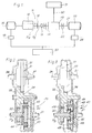
- the propulsion system comprises a controlled- or spontaneous-ignition heat engine 10 equipped with its own mechanical or electronic speed regulator (not shown).
- a generator 15, rotating at the same number of revolutions as the heat engine 10, is directly connected to the heat engine 10.
- the electric generator 15 it is also possible for the electric generator 15 to be driven via a suitable transmission gearing.
- a transmission shaft 11 connects the heat engine to a first input shaft of an epicyclic gearing, generally denoted by 40 and described in more detail below, which connects the engine to the transmission generally denoted by 31 via an output shaft 30 of the epicyclic gearing 40 itself.
- the shaft 11 is divided into two portions 11a and 11b connected together by a clutch 16 which, whenever required, enables the heat engine 10 to be disengaged from the transmission. Downstream of the clutch 16 there is a free wheel 13 which allows the portion 11b of the shaft 11 to rotate only in the direction of rotation of the heat engine, and a brake 14, which prevents rotation of the portion 11b of the shaft 11 in either direction when the clutch 16 is disengaged.
- the free wheel 13 could also be dispensed with.
- a second input shaft of the epicyclic gearing 40 has associated with it, via a shaft 21, an electric traction motor 20 of one of the known types (direct current, separate excitation, permanent magnet, synchronous with variable reluctance, etc.).
- the motor 20 is controlled by a main regulator 25 which, in addition to its own function as regulator of the motor, interacts with the regulator 18, with the speed regulator of the heat engine 10, with the pedal of the accelerator and with a speedometer which detects the speed of the vehicle.
- the shaft 21 may have associated with it a brake 22 which allows said shaft to be locked when this is necessary in order to use only the heat engine in an emergency.
- the system illustrated in Fig. 1 is completed by a set of batteries 50 which are charged by the generator 15 and which supply energy to the electric motor 20.
- the epicyclic gearing 40 may be realized in various ways. It is important, however, that it should be an epicyclic gearing with two input shafts and an output shaft, with the output shaft being connected to the drive wheels, while the input shafts are respectively connected to the heat engine 10 and electric motor 20. Obviously, during free-running or downhill travel, the power input shaft is the transmission shaft and the two output shafts must be braked. Furthermore the internal ratio is chosen so that both the engine 10 and motor 20 contribute, with their characteristic torque, to the formation of the drive torque input to the transmission 31.
- the gearing must allow the addition of power outputs of the same order of magnitude, but with different characteristics, since that of the heat engine is achieved at a high speed with a low torque, whereas that of the electric motor is also obtained at a low number of revolutions with a high torque.
- Figs. 2 and 3 show two possible embodiments of the epicyclic gearing 40.
- a first gear wheel 41 of the gearing 40 is keyed onto the shaft 11b, which receives the movement from the heat engine 10.
- An internal crown gear 42 is keyed onto the shaft 21 actuated by the electric motor 20.
- a series of gear wheels 43 (two of which are visible in Fig. 2), mounted on a planet-wheel carrier or train carrier 44, mesh with the gear 41 and the crown gear 42.
- the train carrier 44 is integral with a gear wheel 30, which represents the output of the epicyclic gearing 40.
- Via a pair of gear wheels 33, 34 the movement is transmitted to the crown gear 35 integral with the housing of a differential 31, the output half-shafts 36, 37 of which transmit the movement to the drive wheels of the vehicle.
- the torques supplied by the engine 10 and motor 20 are introduced via the so-called sun gears of the gearing (i.e. the gear wheel 41 and crown gear 42), the sun gear with a smaller diameter being connected to the heat engine.
- the heat engine operates at a greater angular velocity, supplying a low torque, while the electric motor, which is able to supply a high torque at a low number of revolutions, is connected to the gearing via the sun gear with a larger diameter.
- the portion 11b of the shaft 11 has keyed on it a gear wheel 45 which meshes with a series of gear wheels 46 mounted idly on a train carrier 47 integral with the shaft 21 of the electric motor 20.
- Each gear wheel 46, which rolls on the wheel 45, is integral with a respective gear wheel 48, which rolls on another gear wheel 49 coaxial with the gear wheel 45 and hence with the two shafts 11 and 21.
- the gear wheel 49 is integral with the gear wheel 30 which transmits the movement, via the wheels 33, 34, to the differential 31, in a similar manner to the embodiment according to Fig. 2.
- the torque supplied by the heat engine 10 is introduced into the gearing 40 in this case also via a sun gear of small diameter, while the torque of the electric motor 20 is introduced via the train carrier 47.
- the movement which is output is received by the second sun gear 49.
- the condition is satisfied, whereby the low torque of the heat engine (supplied at a high number of revolutions) is introduced via a wheel of small diameter rotating at high speed, while the high torque supplied at a low operating speed by the electric motor 20 is introduced via a component (train carrier) rotating at a low speed.
- the speed of rotation of the shaft 30, and hence (ultimately) the speed of the vehicle may be varied by varying the speed of either of the drive shafts 21 and 11. Since the heat engine 10 operates within a fixed range (or within a limited number of predetermined speed ranges), variation in the speed of the vehicle is obtained, for each speed range of the heat engine 10, by varying the speed of rotation of the electric motor 21. Moreover, since the resistance torque on the drive wheels of the vehicle, and hence on the output shaft 30 of the gearing 40, is fixed, the distribution of the torques supplied by the engine 10 and motor 20 is determined by the ratio of the gearing. For this reason it is necessary to choose a ratio K which enables the low torque of the heat engine and the high torque of the electric motor to be exploited.
- modulation of the torque C 11 supplied to the epicyclic gearing 40 of the heat engine 10 is obtained by varying the power consumption of the generator 15.
- the clutch 16 In this mode of operation the clutch 16 is disengaged and the brake 14 prevents rotation of the shaft 11b.
- the electric motor 20 ensures traction during forward travel and backward travel by reversing its own direction of rotation, as well as energy recovery during free-running or downhill travel. Reverse travel is possible only in electric mode, or in series hybrid mode if the heat engine 10 is in operation.
- hybrid mode the beginning of the cycle, upon start-up of the vehicle, is similar to electric mode, with the clutch 16 disengaged and the brake 14 applied.
- the accelerator Upon operation of the accelerator the vehicle starts with the electric motor alone, and the heat engine (if not already running) is started up and runs at a speed close to idle speed, charging the batteries.
- This mode of operation corresponds to conventional series hybrid operation.
- the regulator 25 engages the clutch 16 and releases the brake 14.
- the shaft 11b thus starts to rotate and if, during the manoeuvre, the speed of the vehicle is assumed to be constant initially, the revolutions of the electric motor are proportionally reduced as the clutch 16 engages, since a part of the movement is now supplied to the gearing 40 by the heat engine 10.
- the system is now operating in parallel hybrid mode.
- the heat engine 10 Upon reaching a higher speed, the heat engine 10 is accelerated and passes from the preceding operating range to a new operating range with a higher speed of rotation. This may result both in a decrease in the speed of rotation of the electric motor 20 and an increase in the speed of the vehicle. This transition of the heat engine 10 to a higher speed range with a corresponding reduction in the speed of rotation of the electric motor may be repeated several times until higher vehicle speeds are reached in each case, the need for regulation of the heat engine with two or more speed stages depending, inter alia, on the characteristics of the vehicle and the performance required in terms of a reduction in the polluting emissions.
- the regulation system will increase excitation of the electric motor 20 and reduce that of the generator 15 so as to transfer a larger percentage of the torque of the heat engine 10 to the epicyclic gearing 40.
- the control system intervenes, reducing the number of revolutions of the electric motor 20, so as to slow down the vehicle and thus reduce the torque required. If the vehicle slows down beyond a certain speed value, the reverse sequence of operations with respect to that described for acceleration is performed, and the heat engine passes to a lower speed range where it supplies a larger torque. If this is not sufficient because the steepness is still increasing, the speed is further reduced until, at a certain steepness, operation in parallel hybrid mode is no longer possible. As a result the clutch 16 is disengaged, the brake 14 applied and the vehicle advances in series hybrid mode, with all the power supplied by the electric motor 20 and the power of the heat engine 10 being transferred to the generator 15 which supplies the electric motor 20 and/or charges the batteries 50.
Landscapes
- Engineering & Computer Science (AREA)
- Transportation (AREA)
- Mechanical Engineering (AREA)
- Chemical & Material Sciences (AREA)
- Combustion & Propulsion (AREA)
- Automation & Control Theory (AREA)
- Electric Propulsion And Braking For Vehicles (AREA)
Claims (9)
- Système de propulsion hybride pour véhicules, comprenant :un moteur thermique (10) ;des moyens de transmission (31) pour transmettre la puissance envoyée par le système aux roues d'un véhicule ;un générateur électrique (15) connecté en permanence audit moteur thermique (10) et entraíné par ce dernier, ledit générateur électrique (15) étant connecté à des moyens de stockage (50) pour stocker une énergie électrique produite par ledit générateur électrique ;un moteur électrique (20) connecté audit moyen de stockage (50) ;un engrenage planétaire (40) comportant des premier et second arbres d'entrée (11b, 21) et un arbre de sortie (30), ledit moteur thermique (10) et ledit moteur électrique (20) étant raccordés respectivement auxdits premier et second arbres d'entrée (11b, 21) ;
dans lequel le moteur thermique (10) est raccordé audit premier arbre d'entrée (11b) dudit engrenage planétaire (40) au moyen d'un embrayage (16) et d'un frein (14) disposés entre l'embrayage et l'engrenage planétaire (40), le désenclenchement dudit embrayage et le blocage dudit frein (14) amenant ledit système à fonctionner dans le mode uniquement électrique, dans lequel le moteur thermique ne fonctionne pas et toute la puissance est envoyée au moteur électrique par lesdits moyens de stockage, ou dans le mode hybride en série, dans lequel le moteur thermique (10) envoie une puissance au moteur électrique (20) par l'intermédiaire dudit générateur électrique (50) ; l'enclenchement dudit embrayage et le déblocage dudit frein (14) amenant le système à fonctionner dans le mode hybride en parallèle, dans lequel ledit générateur électrique (15) charge lesdits moyens de stockage (50) et dans lequel ledit moteur thermique (10) et ledit moteur électrique (20) délivrent en combinaison une énergie audit moyen de transmission (31). - Système de propulsion selon la revendication 1, caractérisé en ce que le rapport de l'engrenage planétaire (40) est choisi de manière à permettre la combinaison du faible couple délivré pour une vitesse de rotation élevée par le moteur thermique (10) au couple élevé délivré pour une faible vitesse de rotation par le moteur électrique (20).
- Système de propulsion selon la revendication 1 ou 2, caractérisé en ce que l'arbre d'entrée (11b) raccordé au moteur thermique (10) est solidaire d'une première roue planétaire (41) de l'engrenage planétaire (40), l'arbre d'entrée (21) raccordé au moteur électrique (20) est solidaire d'une seconde roue planétaire (42) de l'engrenage planétaire (40) et l'arbre de sortie (30) est articulé au porte-pignon satellite (44) dudit engrenage planétaire.
- Système de propulsion selon la revendication 1 ou 2, caractérisé en ce que l'arbre d'entrée (11b) raccordé au moteur thermique (10) est solidaire d'une première roue planétaire (45) dudit engrenage planétaire (40), l'arbre d'entrée (21) raccordé au moteur électrique (20) est solidaire du porte-pignon satellite (47) de l'engrenage planétaire (40) et l'arbre de sortie (30) est raccordé à une seconde roue planétaire (49) de l'engrenage planétaire (40).
- Système de propulsion selon une ou plusieurs des revendications précédentes, caractérisé en ce que des moyens de freinage (22) sont prévus sur l'arbre (21) qui raccorde le moteur électrique (20) à l'engrenage planétaire (40), le blocage desdits moyens de freinage amenant le moteur thermique (10) à délivrer seul le couple d'entraínement aux moyens de transmission.
- Système de propulsion selon une ou plusieurs des revendications précédentes, caractérisé en ce qu'au moteur électrique (20) est associé un régulateur électronique (25) qui, en fonction des commandes reçues, de la condition de déplacement du véhicule et de la vitesse de rotation du moteur thermique (10) et du générateur (15), commande le moteur électrique (20) en l'amenant à tourner dans un sens de rotation au dans l'autre, avec le couple désiré et la vitesse de rotation désirée, ou l'amène à fonctionner en tant que générateur de courant.
- Système de propulsion selon une ou plusieurs des revendications précédentes, caractérisé en ce que le générateur électrique (15) est commandé par un régulateur électronique (18) qui assume la fonction d'un redresseur, d'un régulateur de tension et d'un dispositif de commande de sortie de la puissance électrique.
- Système de propulsion selon la revendication 6, caractérisé en ce que le moteur thermique (10) est pourvu d'un dispositif de régulation de vitesse, qui est commandé par le régulateur (25) du moteur électrique (20).
- Système de propulsion selon une ou plusieurs des revendications précédentes, caractérisé en ce que le moteur thermique (10) est commandé de manière à fonctionner dans un nombre prédéterminé de conditions de vitesse de rotation stationnaire, le moteur thermique tournant à une vitesse de rotation constante dans chaque condition de vitesse de rotation, pendant le fonctionnement dans n'importe quelle condition faisant partie dudit nombre prédéterminé de conditions de vitesse de rotation du moteur thermique, la vitesse d'avance du véhicule étant commandée par modification de la vitesse de rotation du moteur électrique (20), et la vitesse dudit moteur électrique (20) étant réduite temporairement lorsque le moteur thermique est commuté d'une vitesse de rotation inférieure à une vitesse de rotation supérieure, ou vice-versa.
Priority Applications (2)
| Application Number | Priority Date | Filing Date | Title |
|---|---|---|---|
| DE69320046T DE69320046T2 (de) | 1993-10-14 | 1993-10-14 | Hybridantriebssystem für Fahrzeuge, insbesondere für den städtischen Gebrauch |
| EP93830414A EP0648635B1 (fr) | 1993-10-14 | 1993-10-14 | Système d'entraínement hybride pour véhicules, notamment pour usage urbain |
Applications Claiming Priority (1)
| Application Number | Priority Date | Filing Date | Title |
|---|---|---|---|
| EP93830414A EP0648635B1 (fr) | 1993-10-14 | 1993-10-14 | Système d'entraínement hybride pour véhicules, notamment pour usage urbain |
Publications (2)
| Publication Number | Publication Date |
|---|---|
| EP0648635A1 EP0648635A1 (fr) | 1995-04-19 |
| EP0648635B1 true EP0648635B1 (fr) | 1998-07-29 |
Family
ID=8215233
Family Applications (1)
| Application Number | Title | Priority Date | Filing Date |
|---|---|---|---|
| EP93830414A Expired - Lifetime EP0648635B1 (fr) | 1993-10-14 | 1993-10-14 | Système d'entraínement hybride pour véhicules, notamment pour usage urbain |
Country Status (2)
| Country | Link |
|---|---|
| EP (1) | EP0648635B1 (fr) |
| DE (1) | DE69320046T2 (fr) |
Cited By (2)
| Publication number | Priority date | Publication date | Assignee | Title |
|---|---|---|---|---|
| WO2005097530A1 (fr) * | 2004-04-12 | 2005-10-20 | Tm4 Inc. | Train de transmission destine a un vehicule hybride en serie/parallele |
| DE102011005305A1 (de) * | 2011-03-09 | 2012-09-13 | Kessler & Co Gmbh | Schaltbare Getriebeanordnung |
Families Citing this family (6)
| Publication number | Priority date | Publication date | Assignee | Title |
|---|---|---|---|---|
| US5704440A (en) * | 1995-05-31 | 1998-01-06 | New York Institute Of Technology | Energy distribution method for hydrid electric vehicle |
| FR2777232A1 (fr) | 1998-04-10 | 1999-10-15 | Renault | Dispositif de traction pour vehicule electrique hybride |
| FR2792582B1 (fr) | 1999-04-22 | 2006-11-24 | Renault | Dispositif de propulsion/traction pour vehicule electrique hybride |
| DE19934696A1 (de) * | 1999-07-23 | 2001-05-17 | Zahnradfabrik Friedrichshafen | Elektrodynamisches Antriebssystem |
| US6991571B2 (en) * | 2003-12-09 | 2006-01-31 | Arvinmeritor Technology, Llc | Variable ratio drive system |
| FR3144069A1 (fr) * | 2022-12-22 | 2024-06-28 | Renault S.A.S | Groupe motopropulseur, véhicule automobile équipé d’un tel groupe motopropulseur et procédé de gestion d’énergie |
Citations (1)
| Publication number | Priority date | Publication date | Assignee | Title |
|---|---|---|---|---|
| EP0552140A1 (fr) * | 1992-01-16 | 1993-07-21 | AVL Gesellschaft für Verbrennungskraftmaschinen und Messtechnik mbH.Prof.Dr.Dr.h.c. Hans List | Dispositif d'entraînement |
Family Cites Families (3)
| Publication number | Priority date | Publication date | Assignee | Title |
|---|---|---|---|---|
| DE2502400A1 (de) * | 1975-01-22 | 1976-07-29 | Helmut Koerner | Antriebsaggregat |
| DE2510623A1 (de) * | 1975-03-12 | 1976-09-23 | Helmut Koerner | Antriebsaggregat |
| FR2679839A1 (fr) * | 1991-07-29 | 1993-02-05 | Jeumont Schneider Ind | Equipement moteur hybride comportant un moteur electrique et un moteur primaire tel qu'un moteur non electrique, par exemple thermique ou a turbines ou un moteur asynchrone. |
-
1993
- 1993-10-14 DE DE69320046T patent/DE69320046T2/de not_active Expired - Lifetime
- 1993-10-14 EP EP93830414A patent/EP0648635B1/fr not_active Expired - Lifetime
Patent Citations (1)
| Publication number | Priority date | Publication date | Assignee | Title |
|---|---|---|---|---|
| EP0552140A1 (fr) * | 1992-01-16 | 1993-07-21 | AVL Gesellschaft für Verbrennungskraftmaschinen und Messtechnik mbH.Prof.Dr.Dr.h.c. Hans List | Dispositif d'entraînement |
Non-Patent Citations (1)
| Title |
|---|
| ATZ 87(1985)11, pages 581-584 * |
Cited By (4)
| Publication number | Priority date | Publication date | Assignee | Title |
|---|---|---|---|---|
| WO2005097530A1 (fr) * | 2004-04-12 | 2005-10-20 | Tm4 Inc. | Train de transmission destine a un vehicule hybride en serie/parallele |
| US7222686B2 (en) | 2004-04-12 | 2007-05-29 | Tm4, Inc. | Drive train for series/parallel hybrid vehicle |
| DE102011005305A1 (de) * | 2011-03-09 | 2012-09-13 | Kessler & Co Gmbh | Schaltbare Getriebeanordnung |
| DE102011005305B4 (de) * | 2011-03-09 | 2017-11-02 | Kessler & Co. Gmbh & Co. Kg | Schaltbare Getriebeanordnung |
Also Published As
| Publication number | Publication date |
|---|---|
| DE69320046T2 (de) | 1999-04-01 |
| DE69320046D1 (de) | 1998-09-03 |
| EP0648635A1 (fr) | 1995-04-19 |
Similar Documents
| Publication | Publication Date | Title |
|---|---|---|
| EP1321326B1 (fr) | Système de transmission de puissance pour véhicule hybride | |
| US5823282A (en) | Hybrid vehicle with oil pump selectively driven by the engine, a generator or a motor | |
| US5403244A (en) | Electric vehicle drive train with direct coupling transmission | |
| US6793600B2 (en) | Powertrain for hybrid electric vehicles | |
| US5788006A (en) | Hybrid vehicle | |
| US6991054B2 (en) | Hybrid-vehicle drive system with torque increasing device and driving method thereof | |
| US5627438A (en) | Pulsing control for an inertial drive system for a multi-motor binary array vehicle | |
| US5376869A (en) | Electric vehicle drive train with rollback detection and compensation | |
| US6569055B2 (en) | Four-wheel drive hybrid vehicle | |
| US8062172B2 (en) | Powertrain for a hybrid vehicle with all-wheel drive capability and method for controlling wheel slip | |
| US4495836A (en) | Automotive vehicle power drive system | |
| US6110066A (en) | Parallel hybrid drivetrain | |
| EP2502797B1 (fr) | Système de véhicule hybride et contrôleur | |
| US7694762B2 (en) | Hybrid vehicle powertrain with improved reverse drive performance | |
| US10562402B2 (en) | Control system for hybrid vehicle | |
| US7367910B2 (en) | One-mode input-split electro-mechanical transmission with two fixed speed ratios | |
| US20050082992A1 (en) | Drive train for hybrid electric vehicle | |
| US20020061802A1 (en) | Hybrid vehicle | |
| WO1996022894A9 (fr) | Commande pulsante pour systeme d'entrainement inertiel dans un vehicule a serie binaire de moteurs multiples | |
| US10647190B2 (en) | Control system for hybrid vehicles | |
| US11220171B2 (en) | Drivetrain architecture | |
| WO2015033942A1 (fr) | Système de commande de force d'entraînement pour véhicule | |
| EP0648635B1 (fr) | Système d'entraínement hybride pour véhicules, notamment pour usage urbain | |
| JPH10169485A (ja) | ハイブリッド車両 | |
| EP0925979A2 (fr) | Transmission pour un véhicule automobile |
Legal Events
| Date | Code | Title | Description |
|---|---|---|---|
| PUAI | Public reference made under article 153(3) epc to a published international application that has entered the european phase |
Free format text: ORIGINAL CODE: 0009012 |
|
| AK | Designated contracting states |
Kind code of ref document: A1 Designated state(s): DE ES FR GB IT SE |
|
| 17P | Request for examination filed |
Effective date: 19950928 |
|
| 17Q | First examination report despatched |
Effective date: 19960515 |
|
| GRAG | Despatch of communication of intention to grant |
Free format text: ORIGINAL CODE: EPIDOS AGRA |
|
| GRAG | Despatch of communication of intention to grant |
Free format text: ORIGINAL CODE: EPIDOS AGRA |
|
| GRAH | Despatch of communication of intention to grant a patent |
Free format text: ORIGINAL CODE: EPIDOS IGRA |
|
| GRAH | Despatch of communication of intention to grant a patent |
Free format text: ORIGINAL CODE: EPIDOS IGRA |
|
| GRAA | (expected) grant |
Free format text: ORIGINAL CODE: 0009210 |
|
| AK | Designated contracting states |
Kind code of ref document: B1 Designated state(s): DE ES FR GB IT SE |
|
| PG25 | Lapsed in a contracting state [announced via postgrant information from national office to epo] |
Ref country code: IT Free format text: LAPSE BECAUSE OF FAILURE TO SUBMIT A TRANSLATION OF THE DESCRIPTION OR TO PAY THE FEE WITHIN THE PRE;WARNING: LAPSES OF ITALIAN PATENTS WITH EFFECTIVE DATE BEFORE 2007 MAY HAVE OCCURRED AT ANY TIME BEFORE 2007. THE CORRECT EFFECTIVE DATE MAY BE DIFFERENT FROM THE ONE RECORDED.SCRIBED TIME-LIMIT Effective date: 19980729 Ref country code: ES Free format text: THE PATENT HAS BEEN ANNULLED BY A DECISION OF A NATIONAL AUTHORITY Effective date: 19980729 |
|
| REF | Corresponds to: |
Ref document number: 69320046 Country of ref document: DE Date of ref document: 19980903 |
|
| RAP2 | Party data changed (patent owner data changed or rights of a patent transferred) |
Owner name: LOMBARDINI FABBRICA ITALIANA MOTORI SPA Owner name: DOVERI, NICOLO |
|
| PG25 | Lapsed in a contracting state [announced via postgrant information from national office to epo] |
Ref country code: SE Free format text: LAPSE BECAUSE OF FAILURE TO SUBMIT A TRANSLATION OF THE DESCRIPTION OR TO PAY THE FEE WITHIN THE PRESCRIBED TIME-LIMIT Effective date: 19981029 |
|
| ET | Fr: translation filed | ||
| PLBE | No opposition filed within time limit |
Free format text: ORIGINAL CODE: 0009261 |
|
| STAA | Information on the status of an ep patent application or granted ep patent |
Free format text: STATUS: NO OPPOSITION FILED WITHIN TIME LIMIT |
|
| 26N | No opposition filed | ||
| REG | Reference to a national code |
Ref country code: FR Ref legal event code: TP Ref country code: FR Ref legal event code: CD |
|
| REG | Reference to a national code |
Ref country code: GB Ref legal event code: 732E |
|
| REG | Reference to a national code |
Ref country code: GB Ref legal event code: IF02 |
|
| PGFP | Annual fee paid to national office [announced via postgrant information from national office to epo] |
Ref country code: DE Payment date: 20121029 Year of fee payment: 20 Ref country code: FR Payment date: 20121107 Year of fee payment: 20 |
|
| PGFP | Annual fee paid to national office [announced via postgrant information from national office to epo] |
Ref country code: GB Payment date: 20121025 Year of fee payment: 20 |
|
| REG | Reference to a national code |
Ref country code: DE Ref legal event code: R071 Ref document number: 69320046 Country of ref document: DE |
|
| REG | Reference to a national code |
Ref country code: DE Ref legal event code: R071 Ref document number: 69320046 Country of ref document: DE |
|
| REG | Reference to a national code |
Ref country code: GB Ref legal event code: PE20 Expiry date: 20131013 |
|
| PG25 | Lapsed in a contracting state [announced via postgrant information from national office to epo] |
Ref country code: DE Free format text: LAPSE BECAUSE OF EXPIRATION OF PROTECTION Effective date: 20131015 Ref country code: GB Free format text: LAPSE BECAUSE OF EXPIRATION OF PROTECTION Effective date: 20131013 |