EP0648647A1 - Zweistufige Schneidvorrichtung zur Bildung einer LuftsackEntfaltungsöffnung - Google Patents
Zweistufige Schneidvorrichtung zur Bildung einer LuftsackEntfaltungsöffnung Download PDFInfo
- Publication number
- EP0648647A1 EP0648647A1 EP94115620A EP94115620A EP0648647A1 EP 0648647 A1 EP0648647 A1 EP 0648647A1 EP 94115620 A EP94115620 A EP 94115620A EP 94115620 A EP94115620 A EP 94115620A EP 0648647 A1 EP0648647 A1 EP 0648647A1
- Authority
- EP
- European Patent Office
- Prior art keywords
- panel
- cutter
- door substrate
- door
- substrate panel
- Prior art date
- Legal status (The legal status is an assumption and is not a legal conclusion. Google has not performed a legal analysis and makes no representation as to the accuracy of the status listed.)
- Withdrawn
Links
- 239000000758 substrate Substances 0.000 claims abstract description 77
- 239000006260 foam Substances 0.000 claims description 7
- 230000035515 penetration Effects 0.000 claims description 4
- 125000000391 vinyl group Chemical group [H]C([*])=C([H])[H] 0.000 abstract description 29
- 229920002554 vinyl polymer Polymers 0.000 abstract description 29
- 230000000750 progressive effect Effects 0.000 abstract description 4
- 230000015572 biosynthetic process Effects 0.000 description 4
- 238000005755 formation reaction Methods 0.000 description 4
- 238000010276 construction Methods 0.000 description 3
- 239000000463 material Substances 0.000 description 3
- 238000005452 bending Methods 0.000 description 2
- QLHULAHOXSSASE-UHFFFAOYSA-N butan-2-yl 2-(2-hydroxyethyl)piperidine-1-carboxylate Chemical compound CCC(C)OC(=O)N1CCCCC1CCO QLHULAHOXSSASE-UHFFFAOYSA-N 0.000 description 2
- 238000001514 detection method Methods 0.000 description 2
- 230000000149 penetrating effect Effects 0.000 description 2
- 229920003023 plastic Polymers 0.000 description 2
- 239000004033 plastic Substances 0.000 description 2
- 238000000926 separation method Methods 0.000 description 2
- 208000027418 Wounds and injury Diseases 0.000 description 1
- 230000004913 activation Effects 0.000 description 1
- 238000013459 approach Methods 0.000 description 1
- 235000014510 cooky Nutrition 0.000 description 1
- 230000006378 damage Effects 0.000 description 1
- 230000003111 delayed effect Effects 0.000 description 1
- 238000005530 etching Methods 0.000 description 1
- 238000010097 foam moulding Methods 0.000 description 1
- 238000013467 fragmentation Methods 0.000 description 1
- 238000006062 fragmentation reaction Methods 0.000 description 1
- 238000010438 heat treatment Methods 0.000 description 1
- 230000003116 impacting effect Effects 0.000 description 1
- 230000000977 initiatory effect Effects 0.000 description 1
- 208000014674 injury Diseases 0.000 description 1
- 238000009434 installation Methods 0.000 description 1
- 210000003127 knee Anatomy 0.000 description 1
- 238000003698 laser cutting Methods 0.000 description 1
- 238000000034 method Methods 0.000 description 1
- 230000002441 reversible effect Effects 0.000 description 1
- 238000010008 shearing Methods 0.000 description 1
- 230000000007 visual effect Effects 0.000 description 1
- 230000003313 weakening effect Effects 0.000 description 1
Images


Classifications
-
- B—PERFORMING OPERATIONS; TRANSPORTING
- B60—VEHICLES IN GENERAL
- B60R—VEHICLES, VEHICLE FITTINGS, OR VEHICLE PARTS, NOT OTHERWISE PROVIDED FOR
- B60R21/00—Arrangements or fittings on vehicles for protecting or preventing injuries to occupants or pedestrians in case of accidents or other traffic risks
- B60R21/02—Occupant safety arrangements or fittings, e.g. crash pads
- B60R21/16—Inflatable occupant restraints or confinements designed to inflate upon impact or impending impact, e.g. air bags
- B60R21/20—Arrangements for storing inflatable members in their non-use or deflated condition; Arrangement or mounting of air bag modules or components
- B60R21/215—Arrangements for storing inflatable members in their non-use or deflated condition; Arrangement or mounting of air bag modules or components characterised by the covers for the inflatable member
- B60R21/2165—Arrangements for storing inflatable members in their non-use or deflated condition; Arrangement or mounting of air bag modules or components characterised by the covers for the inflatable member characterised by a tear line for defining a deployment opening
-
- B—PERFORMING OPERATIONS; TRANSPORTING
- B23—MACHINE TOOLS; METAL-WORKING NOT OTHERWISE PROVIDED FOR
- B23K—SOLDERING OR UNSOLDERING; WELDING; CLADDING OR PLATING BY SOLDERING OR WELDING; CUTTING BY APPLYING HEAT LOCALLY, e.g. FLAME CUTTING; WORKING BY LASER BEAM
- B23K26/00—Working by laser beam, e.g. welding, cutting or boring
- B23K26/36—Removing material
- B23K26/362—Laser etching
- B23K26/364—Laser etching for making a groove or trench, e.g. for scribing a break initiation groove
-
- B—PERFORMING OPERATIONS; TRANSPORTING
- B29—WORKING OF PLASTICS; WORKING OF SUBSTANCES IN A PLASTIC STATE IN GENERAL
- B29C—SHAPING OR JOINING OF PLASTICS; SHAPING OF MATERIAL IN A PLASTIC STATE, NOT OTHERWISE PROVIDED FOR; AFTER-TREATMENT OF THE SHAPED PRODUCTS, e.g. REPAIRING
- B29C35/00—Heating, cooling or curing, e.g. crosslinking or vulcanising; Apparatus therefor
- B29C35/02—Heating or curing, e.g. crosslinking or vulcanizing during moulding, e.g. in a mould
- B29C35/08—Heating or curing, e.g. crosslinking or vulcanizing during moulding, e.g. in a mould by wave energy or particle radiation
- B29C35/0805—Heating or curing, e.g. crosslinking or vulcanizing during moulding, e.g. in a mould by wave energy or particle radiation using electromagnetic radiation
- B29C2035/0838—Heating or curing, e.g. crosslinking or vulcanizing during moulding, e.g. in a mould by wave energy or particle radiation using electromagnetic radiation using laser
-
- B—PERFORMING OPERATIONS; TRANSPORTING
- B60—VEHICLES IN GENERAL
- B60R—VEHICLES, VEHICLE FITTINGS, OR VEHICLE PARTS, NOT OTHERWISE PROVIDED FOR
- B60R21/00—Arrangements or fittings on vehicles for protecting or preventing injuries to occupants or pedestrians in case of accidents or other traffic risks
- B60R21/02—Occupant safety arrangements or fittings, e.g. crash pads
- B60R21/16—Inflatable occupant restraints or confinements designed to inflate upon impact or impending impact, e.g. air bags
- B60R21/20—Arrangements for storing inflatable members in their non-use or deflated condition; Arrangement or mounting of air bag modules or components
- B60R21/215—Arrangements for storing inflatable members in their non-use or deflated condition; Arrangement or mounting of air bag modules or components characterised by the covers for the inflatable member
- B60R21/2165—Arrangements for storing inflatable members in their non-use or deflated condition; Arrangement or mounting of air bag modules or components characterised by the covers for the inflatable member characterised by a tear line for defining a deployment opening
- B60R2021/21652—Arrangements for storing inflatable members in their non-use or deflated condition; Arrangement or mounting of air bag modules or components characterised by the covers for the inflatable member characterised by a tear line for defining a deployment opening the tearing being done or assisted by cutters
Definitions
- This invention concerns air bag safety, systems and more particularly arrangements for providing air bag deployment openings in an interior trim structure, i.e., instrument panels, in which the outer surface does not give any visible indication of an air bag deployment door or opening.
- Air bag systems have now come into common use for automotive vehicles, in which one or more air bags are stowed in respective storage spaces located within the passenger compartment.
- a driver's side air bag is stored in a receptacle in the center of the steering wheel and a passenger's side air bag is stored in a receptacle mounted behind the instrument panel.
- the air bag or bags are very rapidly inflated and enter the passenger compartment to be deployed in positions within the passenger compartment so as to cushion the driver and/or passengers from injury which otherwise would be caused by impacting the interior structure of the auto.
- the air bags must be neatly stowed out of sight and so as to be resistant to tampering, yet able to deploy into the passenger compartment in an instant. These requirements necessitate a sturdy closure panel for the deployment opening, preferably installed so as to minimize so as to any visual indication of the presence of the closure, and yet to reliably open under the wide range of ambient temperature conditions for which the auto is designed for use, over the entire useful life of the car (or truck).
- closures are usually opened by a force exerted by the inflating air bag, and the deployment of the air bag must not be appreciably slowed by resistance developed in opening the closure.
- the considerable force applied by the inflating air bag must not result in fragmentation or separation of the closure, lest debris be projected towards persons in the passenger compartment.
- the closure is of necessity exposed within the auto interior, and thus must be aesthetically compatible with the auto interior trim.
- a vinyl skin covering layer is commonly applied to the instrument panel and other trim panel surfaces.
- Plastics such as vinyl, while durable, are relatively tough and resistant to tearing.
- U.S. patent 3,640,546 discloses a closure in which a pair of doors are covered by a covering skin, preweakened along a line of separation; which is ruptured when the doors are forced opened by the deploying air bag.
- the line of weakening is described as being accomplished by a reduction in thickness, perforating, or of heating.
- Such a joint is not sufficiently sturdy to resist inward pressure applied by an occupant and also results in a visible seam.
- Movable piercing cutters have also been proposed, see for example U.S. patent 4,989,896 which describes a piecing cutter positioned to be forced out by the air bag during deployment to penetrate the vinyl skin.
- Another design challenge associated with piercing type cutters is to effectively transfer the energy of the inflating air bag to the cutters without disturbing the proper deployment of the air bag.
- Small area piercing point actuation cannot quickly and effectively absorb the pressure exerted by the air bag, since the area of the air bag is so much greater.
- the vinyl covering layer is particularly difficult to cut when ambient conditions have heated it to an elevated temperature as the material tends to stretch considerably. Substantial loading is required to cut with the cutter shown in U.S. patent 5,035,444, when stretching occurs, and delayed completion of the cutting will retard air bag deployment and thus degrade or defeat the performance of the air bag system.
- the object of the present invention is to provide a mechanical arrangement for reliably cutting a vinyl covering layer to form an air bag deployment opening which arrangement completely and quickly cuts the covering layer in a pattern matching the deployment door sides, while minimizing the loading required to complete the severing of the covering layer.
- the object also is to minimize the hazards to the occupants by operation of the cutter.
- the present invention is an arrangement which carries out a two-stage cutting action of the covering layer, comprising the combination of a first stage cutter comprised of an array of pointed end piercing cutter elements carried by a pivoted cutter panel mounted within the perimeter of the door substrate but having a major portion thereof inclined to extend below the interior side thereof to a level much closer to the stored air bag.
- the cutter panel is positioned to immediately be pushed up by the inflating air bag, the piercing cutters completing a penetration of the covering layer as the cutter panel moves into abutment against the inside of the door substrate panel by the inflating air bag in the initial stage of the air bag system operation.
- the piercing cutter elements are shaped to have a stiffened construction to prevent bending and insure that penetration of the covering layer occurs at particular locations above the substrate door panel within the pattern in which the covering layer is to be severed, as at the center and corners of the door severing pattern.
- the second stage cutter is comprised by the door substrate itself, formed with an out turned rim forming a blunted shearing edge, the rim extending about the unhinged sides of the door substrate panel which rim exerts pressure on the inside of the covering layer along the severing pattern to progressively sever the covering layer in the door pattern perimeter remaining after penetration thereof by the piercing points of the array of piercing cutter elements.
- the rim edge on the door substrate panel projects upwardly from the panel perimeter to a close spacing beneath the covering layer.
- the rim is formed over to blunt the edge and minimize the danger that an occupant could be cut as the door is rapidly swung open by the air bag inflation.
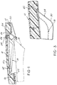
- Figure 1 is a sectional view of a U-shaped air bag deployment door incorporating the two stage cutter arrangement according to the present invention.
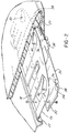
- Figure 2 is a perspective, partially exploded view of the cutter arrangement components of Figure 1 and a fragmentary view of adjacent instrument panel parts.
- Figure 3 is an enlarged sectional view of the deployment door and cutter components and adjacent instrument panel structure.
- Figure 4 is a partially exploded sectional view of the deployment door and cutter components and adjacent instrument panel structure, with the first stage cutter advanced by the air bag against the deployment door substrate.
- Figure 5 is a perspective view of an "H" pattern first stage cutter and second state door substrate cutter together with a fragmentary sectional view of adjacent instrument panel structure.
- Figure 6 is a sectional view of the "H" pattern components with the first stage cutter advanced to the penetrating position.
- Figure 7 is a sectional view of the "H" pattern two stage cutter arrangement.
- the present invention concerns air bag safety systems in which an air bag is stowed in a folded condition behind an interior trim structure, such as the instrument panel for passenger side air bag applications.
- the air bag is rapidly inflated upon detection of a severe collision, with an opening formed into the interior trim structure to allow the air bag to expand into the passenger space just to the rear of the trim structure.
- the embodiment of Figures 1-4 is applied to an instrument panel installation and for a so-called top mounted U-pattern deployment door in which a generally U-shaped door is forced to hinge open along a hinging axis extending across the vehicle width and generally along the direction in which the instrument panel extends.
- the present invention also concerns the so-called "invisible seam" deployment door construction in which no outline of the deployment door or opening is visible from the exterior of the trim piece such as to not encourage tampering and to not make obvious the presence of the air bag to occupants of the vehicle.
- an overlying smooth expanse of a decorative cover layer 10 extends completely over the opening to be formed and over the adjacent regions of the instrument panel 12, here comprising the trim piece behind which an air bag container 14 is mounted.
- the decorative covering layer 10 is underlain by a layer of foam 16 such as to create the smooth uninterrupted contour of the outer upper surface of the instrument panel 12.
- the deployment door is essentially defined by a generally rectangular door substrate panel 18 which is free from any connection to the substrate layer 20 of the instrument panel 12 along three of its four sides but having its fourth side connected to a hinging flange 22 extending along the forward side of the deployment door substrate panel 18.
- the unhinged opposite side of the deployment door substrate panel 18 rests on a stop structure 24 secured to a portion of the instrument panel substrate 20 as shown in Figure 1. This enables the door substrate panel 18 to resist inward pushing pressure while allowing the outward hinging action about the hinge flange 22 upon activation of the air bag system.
- the door substrate panel 18 is formed as a second stage cutter by means of an upturned rim 26 extending about the perimeter of the three free sides of the door substrate panel 18.
- the rim 26 is blunted with a turned out final edge 28 to avoid the presentment of a relatively sharp cutting edge towards the interior of the vehicle passenger compartment while still allowing a concentration of pressure to be applied by the force of the inflating air bag exerted on the substrate panel 18.
- the rim 26 is closely spaced to the inside of the covering layer 10, i.e., .060 inches below the inner surface thereof,
- a first stage piercing cutter panel 30 is provided which is approximately coextensive with the door substrate panel 18.
- the first stage cutter panel 30 is also hinged along its forward side by means of a series of connections 32 to the door substrate panel 18.
- the normal position of the first stage cutter panel 30 is angled downwardly below the undersurface of the substrate door panel 18, inclined downwardly from the hinging side towards the free side of the door substrate panel 18.
- the first stage cutter panel 30 is provided with an array of upwardly projecting piercing elements 34 having peaked piercing points 36 which are located to intersect the vinyl or other decorative covering layer 10 along the same line as will be contacted by the upturned rim 26 of the door substrate panel 18 when the panel 18 is forced up.
- the piercing elements 34 have suitable reenforcing formations 38 to ensure that the elements 34 are sturdy enough to maintain their location even after being forced through the foam layer 16 and against the covering layer 10 by the pressure exerted by the inflating air bag such as to provide for piercing of the vinyl covering layer 10 at the appropriate locations.
- the piercing peaks 36 are located in the center of the free side of the door substrate panel 18 and adjacent each of the corners formed at the intersection of the free sides of the deployment door substrate panel 18. These are the locations where it is most difficult to initiate and/or maintain severing of the covering layer 10, and thus a "prepenetration" aids the action of the second stage cutting.
- the initial location of the first stage cutter panel 30 is substantially closer to the inflated air bag than the door panel 18, and thus is almost immediately contacted by the air bag upon inflation, the first stage cutter panel 30 first forced upwardly, penetrating the vinyl covering layer 10 at the center and corners before the door substrate panel 18 begins to open and apply pressure to the covering layer 10.
- the piercing elements 34 are each received into a respective aligned cut-out opening 40 in the deployment door substrate panel 18.
- the first stage cutter panel 30 will bottom out against the undersurface of the deployment door substrate panel 18 as indicated in Figure 4 after piercing the vinyl decorative covering layer 10 at these three points.
- the deployment door substrate panel 18 progressively continues the severing of the vinyl covering layer 10 by pressure developed by the upturned rim 26 as the deployment door panel 18 swings open about the hinge flange 22 under the pressure of the inflating air bag. Once the vinyl covering layer 10 has been pierced continued progressive cutting is readily achieved by the deployment door substrate panel.
- a groove 42 is cut into the inside of the vinyl covering layer 10, extending along the line of severing of the vinyl covering layer 10 as by scoring, etching, laser cutting, etc., in order to further insure a reliable cutting of the vinyl in the predetermined pattern which will allow the swinging open of the deployment door and the formation of the deployment opening for enabling the air bag to move into the passenger compartment.
- a tape foam seal 44 which can be used to overlie the cut-out openings 40 during the foam molding process in order to prevent the escape of foam and yet allow the piercing element 34 to move upwardly.
- the foam presents only minimal resistance.
- the invention is also applicable to other door patterns such as the "H" pattern shown in Figures 5-7.
- a pair of deployment door substrate panels 46A, 46B are provided, hinged by curved sections 59 along one side of the instrument panel substrate 20.
- Each side of the deployment door substrate panels 46A, 46B has an upturned rim 48 extending along the unhinged sides thereof.
- the deployment door panels 46A, 46B are also joined along their common side by a slotted ridge 50 which defines a frangible edge and also provides a further elevated upturned rim along the side of each deployment door substrate panel 46A, 46B opposite a hinging side 52A, 52B.
- a first stage cutter panel 54 is provided, substantially coextensive with the deployment door substrate panel 46A, and which cutter panel is similar to the above-described "U" door pattern, hinged on one side by a series of riveted connections 56.
- the reverse bend formation of that side of the first stage cutter panel 54 provides a hinging action.
- the first stage cutter panel 54 as in the above-described embodiment is inclined downwardly towards the air bag canister 14 as it extends towards the junction of the two deployment door substrate panels 46A, 46B.
- a knee stop 58 is provided to provide support for the connected deployment doors 46A, 46B substrate panels against inward pressure.
- Each of the substrate panels is reinforced by means of a layer 60 of a rigid foam plastic such as DYTHERM (TM).
- the first stage cutter panel 54 is similarly provided with a series of piercing elements 62 suitably reinforced to be relatively stiff and resistant to bending as by the ribbed formation 64.
- Each element 62 extends through one of two slots 66 in the raised ridge 50 so as to be able to be moved upwardly and to have peaks 63 which penetrate the vinyl covering layer 10 as the first stage cutter panel 54 is swinging against the undersurface of the substrate door panels 46A, 46B as shown in Figure 7.
- the vinyl covering layer 10 is preferably grooved along the inside in the pattern of the door openings to ensure ready severing of the vinyl skin along the correct pattern.
- the two stage cutter arrangement provides a highly reliable initiation and completion of the vinyl covering layer severing process, and yet avoids the use of a much more extensive sharp cutting edge as a relatively blunt cutter can be employed to complete the progressive cutting action, and yet maintaining a high degree of reliability in the cutting action over a wide range of temperature conditions.
Landscapes
- Engineering & Computer Science (AREA)
- Mechanical Engineering (AREA)
- Physics & Mathematics (AREA)
- Optics & Photonics (AREA)
- Plasma & Fusion (AREA)
- Air Bags (AREA)
Applications Claiming Priority (2)
| Application Number | Priority Date | Filing Date | Title |
|---|---|---|---|
| US132299 | 1993-10-05 | ||
| US08/132,299 US5375875A (en) | 1993-10-05 | 1993-10-05 | Two stage cutter arrangement for forming an air bag deployment opening |
Publications (1)
| Publication Number | Publication Date |
|---|---|
| EP0648647A1 true EP0648647A1 (de) | 1995-04-19 |
Family
ID=22453379
Family Applications (1)
| Application Number | Title | Priority Date | Filing Date |
|---|---|---|---|
| EP94115620A Withdrawn EP0648647A1 (de) | 1993-10-05 | 1994-10-04 | Zweistufige Schneidvorrichtung zur Bildung einer LuftsackEntfaltungsöffnung |
Country Status (4)
| Country | Link |
|---|---|
| US (1) | US5375875A (de) |
| EP (1) | EP0648647A1 (de) |
| JP (1) | JPH07164991A (de) |
| CA (1) | CA2133534A1 (de) |
Families Citing this family (32)
| Publication number | Priority date | Publication date | Assignee | Title |
|---|---|---|---|---|
| US5744776A (en) * | 1989-07-14 | 1998-04-28 | Tip Engineering Group, Inc. | Apparatus and for laser preweakening an automotive trim cover for an air bag deployment opening |
| US5999871A (en) * | 1996-08-05 | 1999-12-07 | Delphi Technologies, Inc. | Control method for variable level airbag inflation |
| US5806880A (en) | 1996-09-24 | 1998-09-15 | Davidson Textron Inc. | Frontal weakening of invisible air bag door cover |
| DE19646548C2 (de) * | 1996-10-31 | 1998-08-27 | Sommer Allibert Lignotock Gmbh | Innenverkleidungsteil für Kraftfahrzeuge mit Airbag-Ausrüstung |
| US6050595A (en) * | 1998-02-19 | 2000-04-18 | Textron Automotive Company Inc. | Peel back method and apparatus for deployably concealing an air bag behind an instrument panel |
| US6349963B1 (en) * | 1999-03-18 | 2002-02-26 | Inova Gmbh Technische Entwioldungen | Airbag device |
| FR2802498A1 (fr) | 1999-12-21 | 2001-06-22 | Sai Automotive Allibert Ind | Equipement interieur d'un habitacle de vehicule automobile tel qu'une planche de bord |
| EP1276645A4 (de) * | 2000-03-14 | 2005-02-16 | Am Safe Inc | Luftsack-anordnung |
| US6652128B2 (en) * | 2001-01-31 | 2003-11-25 | Textron Automotive Company, Inc. | Backlighting method for an automotive trim panel |
| EP1431134B1 (de) * | 2002-12-10 | 2006-04-26 | Calsonic Kansei Corporation | Tür einer Airbageinrichtung für Fahrzeug |
| US6942243B2 (en) * | 2002-12-23 | 2005-09-13 | Lear Corporation | Vehicle instrument panel air bag door assembly |
| DE10344401A1 (de) * | 2003-09-25 | 2005-05-12 | Bayerische Motoren Werke Ag | Airbaganordnung, bei der die Airbagabdeckung scharfe Schwächungsabschnitte zum Auftreten der Dekorschicht aufweist |
| US7093850B2 (en) * | 2003-11-14 | 2006-08-22 | Delphi Technologies, Inc. | Instrument panel with integral hidden door cover and method of manufacture thereof |
| DE102005055553A1 (de) * | 2005-11-18 | 2007-05-24 | Johnson Controls Interiors Gmbh & Co. Kg | Verfahren zur Erzeugung einer Schwächungszone, insbesondere einer Sollbruchlinie für eine Airbag-Austrittsöffnung, Bauteil und Vorrichtung |
| US20070246918A1 (en) * | 2006-04-21 | 2007-10-25 | Speelman Phillip B | Instrument panel with integral hidden door cover and method of manufacture thereof |
| DE102006024140B4 (de) * | 2006-05-22 | 2008-10-16 | Faurecia Innenraum Systeme Gmbh | Airbag-Vorrichtung und Kraftfahrzeug-Innenverkleidungsteil |
| US20080315566A1 (en) * | 2007-06-20 | 2008-12-25 | Andrasik Iii Joseph | Instrument panel with integral hidden door cover and method of manufacture thereof |
| US7980590B2 (en) | 2008-03-19 | 2011-07-19 | Amsafe, Inc. | Inflatable personal restraint systems having web-mounted inflators and associated methods of use and manufacture |
| US7665761B1 (en) | 2008-03-27 | 2010-02-23 | Amsafe, Inc. | Inflatable personal restraint systems and associated methods of use and manufacture |
| DE102008056441A1 (de) | 2008-11-07 | 2010-05-12 | Peguform Gmbh | Innenverkleidungsbauteil mit Airbaganordnung |
| DE102009014449A1 (de) | 2009-03-23 | 2010-10-07 | International Automotive Components Group Gmbh | Airbag-Anordnung für ein Kraftfahrzeug und Verfahren zur Herstellung einer Airbag-Anordnung |
| DE102010054573A1 (de) * | 2010-12-15 | 2012-06-21 | Volkswagen Ag | Airbagabdeckung an einem Innenausstattungsteil, insbesondere an einer Instrumententafel eines Fahrzeugs |
| US8469397B2 (en) | 2011-04-13 | 2013-06-25 | Amsafe, Inc. | Stitch patterns for restraint-mounted airbags and associated systems and methods |
| EP2527208B1 (de) | 2011-05-26 | 2013-10-23 | International Automotive Components Group GmbH | Airbag-Abdeckung, insbesondere für Airbags in einem Kraftfahrzeug und Verfahren zu deren Herstellung |
| US8439398B2 (en) | 2011-07-29 | 2013-05-14 | Amsafe, Inc. | Inflator connectors for inflatable personal restraints and associated systems and methods |
| US8523220B1 (en) | 2012-03-19 | 2013-09-03 | Amsafe, Inc. | Structure mounted airbag assemblies and associated systems and methods |
| US9511866B2 (en) | 2012-03-19 | 2016-12-06 | Amsafe, Inc. | Structure mounted airbag assemblies and associated systems and methods |
| DE102012209610A1 (de) * | 2012-06-07 | 2013-12-12 | Faurecia Innenraum Systeme Gmbh | Airbagabdeckung mit einem durch Druck aktivierbaren Element |
| US9352839B2 (en) | 2014-10-02 | 2016-05-31 | Amsafe, Inc. | Active positioning airbag assembly and associated systems and methods |
| US9944245B2 (en) | 2015-03-28 | 2018-04-17 | Amsafe, Inc. | Extending pass-through airbag occupant restraint systems, and associated systems and methods |
| SG11201708221UA (en) | 2015-04-11 | 2017-11-29 | Amsafe Inc | Active airbag vent system |
| US10604259B2 (en) | 2016-01-20 | 2020-03-31 | Amsafe, Inc. | Occupant restraint systems having extending restraints, and associated systems and methods |
Citations (6)
| Publication number | Priority date | Publication date | Assignee | Title |
|---|---|---|---|---|
| US4989896A (en) * | 1988-10-17 | 1991-02-05 | Tip Engineering Group, Inc. | Double door closure for an air bag deployment opening |
| US5035444A (en) * | 1990-10-22 | 1991-07-30 | Davidson Textron Inc. | Single cutter self-piercing cover assembly for airbag |
| US5108128A (en) * | 1990-09-04 | 1992-04-28 | Davidson Textron, Inc. | Self-piercing cover assembly for airbag |
| JPH05185898A (ja) * | 1992-01-10 | 1993-07-27 | Kansei Corp | インストルメントパネル |
| US5280947A (en) * | 1992-11-02 | 1994-01-25 | Davidson Textron Inc. | One piece invisible airbag door and hinge |
| US5316335A (en) * | 1992-12-14 | 1994-05-31 | Davidson Textron Inc. | Self piercing cover assembly air bag |
Family Cites Families (2)
| Publication number | Priority date | Publication date | Assignee | Title |
|---|---|---|---|---|
| US5046758A (en) * | 1990-11-13 | 1991-09-10 | Davidson Textron Inc. | Multi-cutter self-piercing cover assembly for airbag |
| US5154444A (en) * | 1991-04-05 | 1992-10-13 | Davidson Textron Inc. | Air bag retainer with cutting flaps |
-
1993
- 1993-10-05 US US08/132,299 patent/US5375875A/en not_active Expired - Fee Related
-
1994
- 1994-10-03 CA CA002133534A patent/CA2133534A1/en not_active Abandoned
- 1994-10-04 JP JP6240264A patent/JPH07164991A/ja active Pending
- 1994-10-04 EP EP94115620A patent/EP0648647A1/de not_active Withdrawn
Patent Citations (6)
| Publication number | Priority date | Publication date | Assignee | Title |
|---|---|---|---|---|
| US4989896A (en) * | 1988-10-17 | 1991-02-05 | Tip Engineering Group, Inc. | Double door closure for an air bag deployment opening |
| US5108128A (en) * | 1990-09-04 | 1992-04-28 | Davidson Textron, Inc. | Self-piercing cover assembly for airbag |
| US5035444A (en) * | 1990-10-22 | 1991-07-30 | Davidson Textron Inc. | Single cutter self-piercing cover assembly for airbag |
| JPH05185898A (ja) * | 1992-01-10 | 1993-07-27 | Kansei Corp | インストルメントパネル |
| US5280947A (en) * | 1992-11-02 | 1994-01-25 | Davidson Textron Inc. | One piece invisible airbag door and hinge |
| US5316335A (en) * | 1992-12-14 | 1994-05-31 | Davidson Textron Inc. | Self piercing cover assembly air bag |
Non-Patent Citations (1)
| Title |
|---|
| PATENT ABSTRACTS OF JAPAN vol. 17, no. 610 (M - 1508) 10 November 1993 (1993-11-10) * |
Also Published As
| Publication number | Publication date |
|---|---|
| JPH07164991A (ja) | 1995-06-27 |
| US5375875A (en) | 1994-12-27 |
| CA2133534A1 (en) | 1995-04-06 |
Similar Documents
| Publication | Publication Date | Title |
|---|---|---|
| US5375875A (en) | Two stage cutter arrangement for forming an air bag deployment opening | |
| EP0661142B1 (de) | Verfahren zum Schneiden einer komprimierbaren bogenförmigen Kunststoffschicht | |
| US5611564A (en) | Method and treatment for forming an air bag deployment opening in leather covered trim | |
| US6070901A (en) | Automotive instrument panel having an integral airbag | |
| CA2000642C (en) | Double door closure for an air bag deployment opening | |
| JP3735622B2 (ja) | 安定化されたエアーバッグ展開用開口部を備える、継目が隠されたタイプの展開用ドア構造 | |
| US5992876A (en) | Frontal weakening of invisible air bag door cover | |
| US4893833A (en) | Closure for an air bag deployment opening | |
| AU670726B2 (en) | Arrangement for providing an air bag deployment opening | |
| EP0689968B1 (de) | Abdeckung für eine Airbaganordnung | |
| US5478106A (en) | Method and arrangement for forming an air bag deployment opening | |
| KR20040058219A (ko) | 계기 패널, 계기 패널 시스템, 계기 패널 시스템 제조방법 및 열가소성 패널 | |
| US20120223512A1 (en) | Angled tear seams for airbag covers | |
| KR20040095268A (ko) | 에어백 도어 및 에어백 도어의 제조방법 | |
| US6942243B2 (en) | Vehicle instrument panel air bag door assembly | |
| JP3039250U (ja) | 展開ドアの脱離装置を備えた乗物用エアバッグ装置及び自動車パネル組体 | |
| US20100301589A1 (en) | Protective layer for an airbag assembly | |
| JPH08337149A (ja) | エアバッグ組立体のための閉鎖組立体 |
Legal Events
| Date | Code | Title | Description |
|---|---|---|---|
| PUAI | Public reference made under article 153(3) epc to a published international application that has entered the european phase |
Free format text: ORIGINAL CODE: 0009012 |
|
| AK | Designated contracting states |
Kind code of ref document: A1 Designated state(s): AT BE CH DE DK ES FR GB GR IE IT LI LU MC NL PT SE |
|
| RAX | Requested extension states of the european patent have changed |
Free format text: SI |
|
| STAA | Information on the status of an ep patent application or granted ep patent |
Free format text: STATUS: THE APPLICATION IS DEEMED TO BE WITHDRAWN |
|
| 18D | Application deemed to be withdrawn |
Effective date: 19951020 |