EP0648922B1 - Conduit d'échappement à motif isolé par une couche d'air pour moteurs à combustion interne - Google Patents
Conduit d'échappement à motif isolé par une couche d'air pour moteurs à combustion interne Download PDFInfo
- Publication number
- EP0648922B1 EP0648922B1 EP94303137A EP94303137A EP0648922B1 EP 0648922 B1 EP0648922 B1 EP 0648922B1 EP 94303137 A EP94303137 A EP 94303137A EP 94303137 A EP94303137 A EP 94303137A EP 0648922 B1 EP0648922 B1 EP 0648922B1
- Authority
- EP
- European Patent Office
- Prior art keywords
- liner
- jacket
- air gap
- inlet
- exhaust conduit
- Prior art date
- Legal status (The legal status is an assumption and is not a legal conclusion. Google has not performed a legal analysis and makes no representation as to the accuracy of the status listed.)
- Expired - Lifetime
Links
Images



Classifications
-
- F—MECHANICAL ENGINEERING; LIGHTING; HEATING; WEAPONS; BLASTING
- F01—MACHINES OR ENGINES IN GENERAL; ENGINE PLANTS IN GENERAL; STEAM ENGINES
- F01N—GAS-FLOW SILENCERS OR EXHAUST APPARATUS FOR MACHINES OR ENGINES IN GENERAL; GAS-FLOW SILENCERS OR EXHAUST APPARATUS FOR INTERNAL-COMBUSTION ENGINES
- F01N13/00—Exhaust or silencing apparatus characterised by constructional features
- F01N13/08—Other arrangements or adaptations of exhaust conduits
- F01N13/10—Other arrangements or adaptations of exhaust conduits of exhaust manifolds
- F01N13/102—Other arrangements or adaptations of exhaust conduits of exhaust manifolds having thermal insulation
-
- F—MECHANICAL ENGINEERING; LIGHTING; HEATING; WEAPONS; BLASTING
- F01—MACHINES OR ENGINES IN GENERAL; ENGINE PLANTS IN GENERAL; STEAM ENGINES
- F01N—GAS-FLOW SILENCERS OR EXHAUST APPARATUS FOR MACHINES OR ENGINES IN GENERAL; GAS-FLOW SILENCERS OR EXHAUST APPARATUS FOR INTERNAL-COMBUSTION ENGINES
- F01N13/00—Exhaust or silencing apparatus characterised by constructional features
- F01N13/14—Exhaust or silencing apparatus characterised by constructional features having thermal insulation
-
- F—MECHANICAL ENGINEERING; LIGHTING; HEATING; WEAPONS; BLASTING
- F01—MACHINES OR ENGINES IN GENERAL; ENGINE PLANTS IN GENERAL; STEAM ENGINES
- F01N—GAS-FLOW SILENCERS OR EXHAUST APPARATUS FOR MACHINES OR ENGINES IN GENERAL; GAS-FLOW SILENCERS OR EXHAUST APPARATUS FOR INTERNAL-COMBUSTION ENGINES
- F01N13/00—Exhaust or silencing apparatus characterised by constructional features
- F01N13/14—Exhaust or silencing apparatus characterised by constructional features having thermal insulation
- F01N13/141—Double-walled exhaust pipes or housings
-
- F—MECHANICAL ENGINEERING; LIGHTING; HEATING; WEAPONS; BLASTING
- F01—MACHINES OR ENGINES IN GENERAL; ENGINE PLANTS IN GENERAL; STEAM ENGINES
- F01N—GAS-FLOW SILENCERS OR EXHAUST APPARATUS FOR MACHINES OR ENGINES IN GENERAL; GAS-FLOW SILENCERS OR EXHAUST APPARATUS FOR INTERNAL-COMBUSTION ENGINES
- F01N13/00—Exhaust or silencing apparatus characterised by constructional features
- F01N13/08—Other arrangements or adaptations of exhaust conduits
-
- Y—GENERAL TAGGING OF NEW TECHNOLOGICAL DEVELOPMENTS; GENERAL TAGGING OF CROSS-SECTIONAL TECHNOLOGIES SPANNING OVER SEVERAL SECTIONS OF THE IPC; TECHNICAL SUBJECTS COVERED BY FORMER USPC CROSS-REFERENCE ART COLLECTIONS [XRACs] AND DIGESTS
- Y10—TECHNICAL SUBJECTS COVERED BY FORMER USPC
- Y10S—TECHNICAL SUBJECTS COVERED BY FORMER USPC CROSS-REFERENCE ART COLLECTIONS [XRACs] AND DIGESTS
- Y10S138/00—Pipes and tubular conduits
- Y10S138/11—Shape
Definitions
- This invention relates to dual wall, air gap engine exhaust conduits, such as exhaust pipes, downpipes, exhaust manifolds and the like, and more particularly to air gap exhaust conduits having superior acoustical properties and excellent thermal operational efficiency.
- DE-A-32 16980 discloses a dual wall exhaust conduit having an outer jacket and a thick inner liner.
- the jacket is provided with apertures for ventilating the inner space between the jacket and liner.
- An object of this invention is to provide an engine exhaust conduit such as a downpipe or an exhaust manifold that has excellent thermal efficiency so as to cause rapid "light off" of the catalytic converter after engine startup, and that also provides improved acoustical characteristics.
- an air gap engine exhaust conduit comprises a dual wall, air gap, metal exhaust conduit having an outer jacket and a thin inner liner, the jacket inlet and the liner inlet being adjacent each other; the liner being secured to the jacket adjacent the jacket inlet and the liner inlet, the liner outlet being in direct or indirect engagement with the jacket, and the liner otherwise being spaced from said jacket to form an air gap from said liner inlet to said liner outlet; and is characterised by a pattern of elongated, concave or convex indentation ribs protruding from at least one of said jacket and said liner, over substantially all the length of at least one of said jacket and said liner, the indentation ribs being spaced from the other of said jacket and said liner to maintain a continuous air gap from the liner inlet to the liner outlet.
- the indentations preferably protrude from the jacket toward, but definitely stop short of, the liner, so as to be spaced from and not engage the liner, thereby maintaining a continuous air gap between the liner and the jacket.
- the indentations may protrude externally.
- the ribs may be concave or convex.
- the resulting structure has been found to achieve the necessary emission control qualities, and also lower sound levels as well as having better, more mellow, acoustical quality compared to prior known structures.
- the exhaust conduit downpipe 10 there shown comprises a tubular member having an air gap construction formed by an outer jacket 12 and an inner liner 14 which are held spaced apart from each other over their length, being secured together at both the inlet end and the outlet end.
- the inlet end preferably includes an annular coupling 16 which secures inner liner 14 to outer jacket 12, as well as being useful for connection to an exhaust manifold outlet (not shown).
- the outlet end includes a spacer connector 18 securing liner 14 to jacket 12 and being in indirect contact therewith.
- Both the liner and the jacket are preferably formed of stainless steel, with liner 14 typically being considerably thinner so as to optimize rapid temperature rise from heat exchange with exhaust gases passing therethrough.
- This exhaust conduit downpipe may be attached, for example, in a conventional fashion, to an exhaust manifold at inlet coupling 16, and attached at the outlet end of downpipe 10 to a downstream exhaust conduit components such as a catalytic converter and a muffler (silencer).
- a downstream exhaust conduit components such as a catalytic converter and a muffler (silencer).
- a catalytic converter and a muffler silica muffler
- Each indentation is here shown as a concavity, as viewed from the exterior, and which protrudes toward but stops short of the inner liner 14 so as not to engage the liner. It is important that these concavities not engage liner 14 since that would detract markedly from the thermal efficiency of the unit by providing a heat sink with substantial thermal inertia.
- the indentations may alternatively protrude outwardly to form convexities as viewed from the exterior, or concavities when viewed from the interior.
- the pattern of the embodiment in Fig. 1 includes not only a plurality of spaced annular concavities 20 extending around the pipe, but also axially elongated concavities 22 running substantially the length of downpipe 10.
- Concavities 22 are at circumferentially spaced intervals around the downpipe.
- Axial concavities 22 and annular concavities 20 cross each other to form a plurality of block-type segments in a generally "waffle-type" pattern.
- Experimental testing with the downpipe has shown remarkable acoustical improvement for the exhaust system.
- the indentation pattern in the outer jacket, without touching the inner liner and thus leaving the elongated air gap, has been shown to cause markedly superior acoustical characteristics over previous air gap exhaust conduit units. This superior performance in sound radiation is not fully understood, but is believed due to various factors including the wall being rendered more rigid by the indentation pattern, and the sound waves emanating from the surface being rendered, by the unevenness of the surface, more diffused.
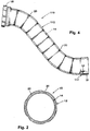
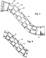
- Fig. 3 is shown a modified form of downpipe 50 wherein the outer jacket 62 has the series of annular concavities 20 as in the first embodiment, but the axially oriented concavities 72 are peripherally offset in each axial segment so as to form an aligned, "brick-type" pattern. More specifically, the axial grooves 72 in one axial segment between two adjacent annular concavities 20 are circumferentially offset from the axially oriented concavities 72 in the segments in both directions thereof. In this embodiment also, these concavities 20 and 72 protrude radially inwardly toward the inner liner 14 (optionally outwardly), but spaced therefrom, so as not to interrupt the continuous air gap extending between the ends of the conduit.
- this downpipe 110 has an inner liner 14 spaced from an outer jacket 112 so as to form a continuous air gap extending between the ends of the conduit, and specifically the inlet end where attachment coupling 16 is located, and the outlet end where annular spacer connector member 18 secures the liner and jacket together.
- Substantially over the length of the jacket is the plurality of annular concavities 20, axially spaced from each other. Each concavity protrudes radially inwardly toward liner 14 (optionally outwardly), with a curvilinear configuration, but terminating short of the liner, so as not to cause heat sink characteristics by thermal conductivity from the liner to the jacket.
- the downpipe 150 in Fig. 5 comprises an outer jacket 162 and an inner liner 14 spaced therefrom over the length of the downpipe.
- outer jacket 162 has a plurality of elongated continuous indentations 122 extending substantially the length of the conduit and spaced from each other around the periphery of jacket 162.
- concavities 122 protrude radially inwardly toward liner 14 but do not physically engage it, being spaced therefrom to not interrupt the continuous air gap between the ends of the conduit.
- the liner could have a rib pattern like those in the above-described embodiments. If so, the rib indentations could be inward or outward, i.e., concave or convex as viewed from the exterior, but with the ribs not engaging the jacket.
- FIGs. 6, 7 and 8 are shown an exhaust manifold conduit 200 including an elongated, planar, port flange 210 to which inlet passages or runners 212 of the manifold are secured as by welding 214.
- the connection of each inlet passage 212 to port flange 210 is with an adapter sleeve 230 which is weldably attached to port flange 210 on one end and weldably attached to liner 224 and jacket 222 on its other end, the liner and jacket extending over the outer periphery of adapter sleeve 230.
- the manifold thus has a plurality of inlets through the runners 212 to the common leg 216 which forms the common conduit for all of the exhaust passing to the outlet 218, at which is a connector flange 220 of conventional type.
- the manifold comprises he outer jacket 222 and an inner liner 224 (Fig. 7), both of steel, preferably stainless steel.
- the liner 224 has inlet passages which extend through inlet passages 212 and a common collector portion extending through collector 216. In this illustrated structure, the liner terminates short of the exit of jacket 222 at the outlet 218.
- Inner liner 224 is shown to terminate at its outlet end short of the outlet of jacket 222. In some manifolds, however, the liner outlet may extend to the jacket outlet.
- Liner 224 is shown to be of the clamshell type, having two longitudinally secured seams 224' secured together as by welding.
- Jacket 222 is also shown to be of the clamshell type, having two portions secured together along longitudinal seams 222'.
- a pattern formed into the jacket 222 is a pattern, here shown to be a waffle-type pattern, of indentation concavities or ribs extending lengthwise, 232, and crosswise, 234, of the manifold jacket, crossing each other. These concavities are shown to protrude inwardly toward liner 224, but terminate short thereof, so as not to make physical contact with liner 224.
- the result of this combination is a manifold with short heatup time, low thermal inertia, and yet improved acoustical characteristics.
- the ribs in the manifold jacket could alternatively extend outwardly, i.e., convex as viewed from the exterior, rather than concave.
- the liner may have indentation ribs which protrude inwardly or outwardly, but if the latter, not engaging the jacket.
- a liner 14' having a series of annular rib concavities 21, and axially oriented concavities 73, in a brick-type pattern.
- This liner is to be combined with a jacket which may or may not have indentation ribs as described previously.
- one of the other type patterns could be applied to the exhaust manifold, the illustrated one being exemplary.
Landscapes
- Engineering & Computer Science (AREA)
- Chemical & Material Sciences (AREA)
- Combustion & Propulsion (AREA)
- Mechanical Engineering (AREA)
- General Engineering & Computer Science (AREA)
- Exhaust Silencers (AREA)
- Thermal Insulation (AREA)
- Rigid Pipes And Flexible Pipes (AREA)
Claims (9)
- Conduit d'échappement pour moteur avec couche d'air intermédiaire comprenant : une double paroi, une couche d'air intermédiaire, un conduit d'échappement en métal (10 ; 50 ; 110 ; 200) avec une chemise externe (12 ; 62 ; 112 ; 162) et un revêtement intérieur mince (14 ; 62 ; 224), l'entrée de la chemise et l'entrée du revêtement étant adjacentes l'une à l'autre ; le revêtement étant fixé à la chemise adjacente à l'entrée de la chemise et à l'entrée du revêtement, la sortie du revêtement s'engageant par ailleurs directement ou indirectement dans la chemise, ledit revêtement se trouvant à une certaine distance de ladite chemise pour former une couche d'air intermédiaire entre ladite entrée du revêtement et ladite sortie de revêtement ; caractérisée par un motif de nervures dentelées concaves ou convexes, allongées (20, 22 ; 20, 72 ; 122 ; 232, 234) en saillie par rapport au moins à la chemise ou au revêtement, pour recouvrir plus ou moins toute la longueur d'au moins une telle chemise et/ou au moins un tel revêtement, les nervures dentelées étant distantes de l'autre chemise et de l'autre revêtement pour maintenir la couche d'air intermédiaire continue séparant l'entrée du revêtement de la sortie du revêtement.
- Conduit d'échappement pour moteur avec couche d'air intermédiaire selon la revendication 1, où lesdites nervures dentelées (20, 22) présentent un motif grillagé ou bien où lesdites nervures dentelés (232, 234) sont disposées selon un motif de briques décalées.
- Conduit d'échappement pour moteur avec couche d'air intermédiaire selon la revendication 1 où lesdites nervures dentelées sont agencées en anneaux espacés (20, 22) entourant ledit conduit, ou bien où lesdites nervures dentelées (122) s'étendent le long dudit conduit.
- Conduit d'échappement pour moteur avec couche d'air intermédiaire selon la revendication 1 ou la revendication 2 ou la revendication 3, où ledit conduit est un tuyau descendant (10, 50, 110).
- Conduit d'échappement pour moteur avec couche d'air intermédiaire selon la revendication 1, où le conduit est un coude d'échappement (200) dont, de préférence, la chemise présente un certain nombre d'entrées et dont le revêtement présente un certain nombre d'entrées, les deux éléments étant fixés à une bride d'ouverture (210).
- Conduit d'échappement pour moteur avec couche d'air intermédiaire selon la revendication 5 où ledit coude présente un certain nombre de passages d'entrée (212) et un collecteur (216), tandis que lesdits passages d'entrée possèdent lesdites entrées de chemise et lesdites entrées de revêtement et tandis que ledit collecteur possède une sortie présentant ledit motif, les nervures dentelées (232, 234) étant transversales l'une par rapport à l'autre.
- Conduit d'échappement pour moteur avec couche d'air intermédiaire selon l'une des revendications 1 à 6, où lesdites nervures dentelées (20, 22 ; 20, 72 ; 122 ; 232, 234) se trouvent dans ladite chemise.
- Conduit d'échappement pour moteur avec couche d'air intermédiaire selon la revendication 7, où les nervures sont en saillie vers ledit revêtement et se terminent juste avant d'atteindre ledit revêtement.
- Conduit d'échappement pour moteur avec couche d'air intermédiaire selon l'une quelconque des revendications 1 à 6, où lesdites nervures dentelées se trouvent dans ledit revêtement.
Applications Claiming Priority (2)
| Application Number | Priority Date | Filing Date | Title |
|---|---|---|---|
| US136415 | 1987-12-22 | ||
| US08/136,415 US5495873A (en) | 1993-10-13 | 1993-10-13 | Patterned air gap engine exhaust conduit |
Publications (2)
| Publication Number | Publication Date |
|---|---|
| EP0648922A1 EP0648922A1 (fr) | 1995-04-19 |
| EP0648922B1 true EP0648922B1 (fr) | 1997-09-17 |
Family
ID=22472761
Family Applications (1)
| Application Number | Title | Priority Date | Filing Date |
|---|---|---|---|
| EP94303137A Expired - Lifetime EP0648922B1 (fr) | 1993-10-13 | 1994-04-29 | Conduit d'échappement à motif isolé par une couche d'air pour moteurs à combustion interne |
Country Status (6)
| Country | Link |
|---|---|
| US (1) | US5495873A (fr) |
| EP (1) | EP0648922B1 (fr) |
| JP (1) | JP2916987B2 (fr) |
| AT (1) | ATE158379T1 (fr) |
| DE (1) | DE69405675T2 (fr) |
| ES (1) | ES2108940T3 (fr) |
Families Citing this family (24)
| Publication number | Priority date | Publication date | Assignee | Title |
|---|---|---|---|---|
| DE4316333C1 (de) * | 1993-05-15 | 1994-09-15 | Mtu Friedrichshafen Gmbh | Abgasleitung |
| DE19546509A1 (de) * | 1995-12-13 | 1997-06-19 | Zeuna Staerker Kg | Abgaskrümmer sowie Verfahren zu seiner Herstellung |
| JP2902364B2 (ja) * | 1996-10-14 | 1999-06-07 | バンドー化学株式会社 | エアインテークダクト用中空管状体並びにその成形金型及びその成形方法 |
| US6209319B1 (en) * | 1998-09-28 | 2001-04-03 | Honda Giken Kogyo Kabushiki Kaisha | Pipe assembly having inner and outer pipes |
| DE19923557B4 (de) * | 1999-05-21 | 2006-07-13 | Daimlerchrysler Ag | Gebauter luftspaltisolierter Abgaskrümmer einer Abgasanlage eines Kraftfahrzeuges und ein Verfahren zu dessen Herstellung |
| JP3786918B2 (ja) * | 2000-10-11 | 2006-06-21 | サムスン エレクトロニクス カンパニー リミテッド | 移動通信システムにおける物理ダウンリンク共有チャネルの伝送アンテナアレイ制御装置及び方法 |
| CN1222378C (zh) * | 2001-05-22 | 2005-10-12 | 三菱自动车工业株式会社 | 液压成形工艺 |
| US6530225B1 (en) | 2001-09-21 | 2003-03-11 | Honeywell International, Inc. | Waffle cooling |
| DE10157131C2 (de) * | 2001-11-21 | 2003-11-13 | Benteler Automobiltechnik Gmbh | Abgasleitung und Verfahren zur Herstellung einer Abgasleitung |
| US20050011573A1 (en) * | 2003-07-14 | 2005-01-20 | American Boa, Inc. | Flexible liner air gap pipe |
| US6990806B1 (en) | 2003-09-02 | 2006-01-31 | Jess Arthur Kinsel | Exhaust header for internal combustion engine |
| KR100952765B1 (ko) * | 2004-09-28 | 2010-04-14 | 갈 운트 자잇츠 시스템즈 게엠베하 | 대기압으로부터 700 바아 까지의 고분사 압력용 연료 분사 이중 벽 파이프 |
| FR2876147B1 (fr) * | 2004-10-01 | 2011-04-22 | Faurecia Sys Echappement | Conduit d'echappement |
| FR2905979B1 (fr) * | 2006-09-15 | 2011-03-18 | Faurecia Sys Echappement | Collecteur d'echappement a double paroi |
| DE102006056351A1 (de) * | 2006-11-29 | 2008-06-05 | Arvinmeritor Emissions Technologies Gmbh | Abgasführende Vorrichtung, Werkzeug zur Querschnittsverringerung sowie Verfahren zur Herstellung einer abgasführenden Vorrichtung |
| CA2656459C (fr) * | 2008-02-29 | 2012-05-22 | Jeffrey Weisel | Tuyau souple cannele pour traite laitiere |
| US20120304656A1 (en) * | 2011-06-06 | 2012-12-06 | General Electric Company | Combustion liner and transition piece |
| DE102013200790A1 (de) * | 2013-01-18 | 2014-07-24 | Robert Bosch Gmbh | Kühlsystem mit einem kühlmitteldurchströmten Kühlkörper zur Kühlung einer Batterie |
| US9874223B2 (en) * | 2013-06-17 | 2018-01-23 | Pratt & Whitney Canada Corp. | Diffuser pipe for a gas turbine engine and method for manufacturing same |
| DE102013109199A1 (de) * | 2013-08-26 | 2015-02-26 | Witzenmann Gmbh | Leitung mit Wölbstruktur |
| US9650149B2 (en) * | 2014-12-08 | 2017-05-16 | Honeywell International Inc. | Fire containment apparatuses for aircraft duct assemblies |
| JP6484038B2 (ja) * | 2015-01-15 | 2019-03-13 | 三桜工業株式会社 | パイプ、金型、及びパイプ製造方法 |
| US10794203B2 (en) * | 2017-03-22 | 2020-10-06 | General Electric Company | Scavenge tube for a gas turbine engine |
| US10948108B2 (en) * | 2017-05-02 | 2021-03-16 | Unison Industries, Llc | Turbine engine duct |
Citations (1)
| Publication number | Priority date | Publication date | Assignee | Title |
|---|---|---|---|---|
| US5170557A (en) * | 1991-05-01 | 1992-12-15 | Benteler Industries, Inc. | Method of forming a double wall, air gap exhaust duct component |
Family Cites Families (32)
| Publication number | Priority date | Publication date | Assignee | Title |
|---|---|---|---|---|
| US421366A (en) * | 1890-02-11 | Sheet-metal pipe | ||
| US531000A (en) * | 1894-12-18 | William morrison | ||
| CH8204A (de) * | 1894-03-10 | 1894-09-15 | Julius Justus | Neue Wärmeschutzplatte |
| US1218895A (en) * | 1914-02-10 | 1917-03-13 | Edwin H Porter | Pipe for the conveyance of fluids. |
| US2179057A (en) * | 1937-05-03 | 1939-11-07 | United States Gypsum Co | Heat insulation |
| US2259433A (en) * | 1937-11-15 | 1941-10-14 | Hoover Co | Heat exchanger |
| US2451131A (en) * | 1940-09-06 | 1948-10-12 | Vidal Corp | Method of making reinforced structures |
| FR669635A (fr) * | 1947-07-19 | 1929-11-19 | Nordberg Manufacturing Co | Perfectionnements aux broyeurs |
| US2667041A (en) * | 1948-10-27 | 1954-01-26 | Ray M Henderson | Evaporator and drip catcher arrangement for refrigerating apparatus |
| US2878837A (en) * | 1956-12-03 | 1959-03-24 | Stewart Warner Corp | Pneumatic jacket for aircraft combustion apparatus |
| US3133612A (en) * | 1960-07-06 | 1964-05-19 | Chrysler Corp | Sound deadening laminated engine exhaust pipe |
| US3340711A (en) * | 1965-03-11 | 1967-09-12 | Reynolds Metals Co | Hollow panel system |
| US3543878A (en) * | 1969-08-19 | 1970-12-01 | Chrysler Corp | Automobile exhaust muffler |
| US3911961A (en) * | 1970-09-25 | 1975-10-14 | Federal Mogul Corp | High temperature duct insulator and method of making same |
| DE2134278C3 (de) * | 1971-07-09 | 1978-06-01 | Licentia Patent-Verwaltungs-Gmbh, 6000 Frankfurt | Absorptionskühlaggregat |
| JPS49112022A (fr) * | 1973-03-02 | 1974-10-25 | ||
| US4037626A (en) * | 1975-09-15 | 1977-07-26 | Standard Oil Company (Indiana) | High strength composite pipe structure having leakproof joints |
| JPS5916085B2 (ja) * | 1976-05-18 | 1984-04-13 | トヨタ自動車株式会社 | 内燃機関用二重排気管の構造 |
| DE2915838A1 (de) * | 1979-04-17 | 1980-10-23 | Mannesmann Ag | Doppelwandrohr fuer auspuffrohre o.dgl. |
| US4585059A (en) * | 1980-01-15 | 1986-04-29 | H & H Tube & Mfg. Co. | Heat transfer tube assembly |
| JPS56157313U (fr) * | 1980-04-24 | 1981-11-24 | ||
| JPS5939632B2 (ja) * | 1980-09-09 | 1984-09-25 | 新日本製鐵株式会社 | 制振2重鋼管 |
| US4484785A (en) * | 1981-04-27 | 1984-11-27 | Sperry-Sun, Inc. | Tubing protector |
| JPS6145289Y2 (fr) * | 1981-05-19 | 1986-12-19 | ||
| DE3216980A1 (de) * | 1982-05-06 | 1983-11-10 | Zeuna-Stärker GmbH & Co KG, 8900 Augsburg | Blechkruemmer fuer verbrennungsmotoren |
| US4615359A (en) * | 1982-08-30 | 1986-10-07 | Affa Stephen N | Shroud for aircraft duct |
| JPS5939724U (ja) * | 1982-09-07 | 1984-03-14 | 片山工業株式会社 | 内燃機関の複層排気管 |
| US4501302A (en) * | 1983-10-14 | 1985-02-26 | Apx Group, Inc. | Air gap pipe |
| JPS6165231U (fr) * | 1984-10-02 | 1986-05-02 | ||
| JPS6268668A (ja) * | 1985-09-24 | 1987-03-28 | Isuzu Motors Ltd | エキゾ−ストマニホ−ルドの製造法 |
| DE3714761A1 (de) * | 1987-05-02 | 1988-11-17 | Witzenmann Metallschlauchfab | Abgasleitung fuer verbrennungsmotoren |
| US4821840A (en) * | 1988-01-20 | 1989-04-18 | Ap Parts Manufacturing Company | Stamp formed exhaust muffler with conformal outer shell |
-
1993
- 1993-10-13 US US08/136,415 patent/US5495873A/en not_active Expired - Lifetime
-
1994
- 1994-04-29 EP EP94303137A patent/EP0648922B1/fr not_active Expired - Lifetime
- 1994-04-29 ES ES94303137T patent/ES2108940T3/es not_active Expired - Lifetime
- 1994-04-29 AT AT94303137T patent/ATE158379T1/de not_active IP Right Cessation
- 1994-04-29 DE DE69405675T patent/DE69405675T2/de not_active Expired - Lifetime
- 1994-05-16 JP JP6124709A patent/JP2916987B2/ja not_active Expired - Fee Related
Patent Citations (1)
| Publication number | Priority date | Publication date | Assignee | Title |
|---|---|---|---|---|
| US5170557A (en) * | 1991-05-01 | 1992-12-15 | Benteler Industries, Inc. | Method of forming a double wall, air gap exhaust duct component |
Also Published As
| Publication number | Publication date |
|---|---|
| EP0648922A1 (fr) | 1995-04-19 |
| DE69405675T2 (de) | 1998-04-09 |
| ATE158379T1 (de) | 1997-10-15 |
| DE69405675D1 (de) | 1997-10-23 |
| US5495873A (en) | 1996-03-05 |
| JPH07109922A (ja) | 1995-04-25 |
| ES2108940T3 (es) | 1998-01-01 |
| JP2916987B2 (ja) | 1999-07-05 |
Similar Documents
| Publication | Publication Date | Title |
|---|---|---|
| EP0648922A1 (fr) | Conduit d'échappement à motif isolé par une couche d'air pour moteurs à combustion interne | |
| JPH0647928B2 (ja) | 音減衰装置 | |
| CA2154720A1 (fr) | Silencieux pour systeme d'echappement | |
| US5014510A (en) | Exhaust system, particularly for two-stroke cycle internal combustion engines | |
| US3522863A (en) | Glass-packed muffler | |
| EP1091101B1 (fr) | Système de ligne d'échappement à conduit double | |
| US5706655A (en) | Thin-walled double pipe exhaust manifold | |
| KR950001064A (ko) | 배기가스 촉매 처리용 촉매식 컨버터 | |
| MY127569A (en) | Exhaust manifold | |
| US3561562A (en) | Automotive exhaust system units | |
| GB2122683A (en) | Exhaust manifold for multi- cylinder motor-vehicle engines | |
| JP2959307B2 (ja) | 内燃機関の排気管 | |
| JPS6217087B2 (fr) | ||
| JP2005163621A (ja) | 触媒コンバータ | |
| JPH0681627A (ja) | エンジン用排気消音器 | |
| JPH07208160A (ja) | エキゾーストマニホールド | |
| EP2751463B1 (fr) | Ensemble de conduits et système d'échappement | |
| JPH07224649A (ja) | 排気マニホルド構造 | |
| CN218991716U (zh) | 一种180度异形连接蚌壳 | |
| JPH08338238A (ja) | 二重管型排気マニホールド | |
| US6103202A (en) | Catalytic converter and pipe assembly | |
| JPH0122891Y2 (fr) | ||
| JP4307623B2 (ja) | 消音器 | |
| JPH0343363Y2 (fr) | ||
| JP3758521B2 (ja) | 排気マフラー |
Legal Events
| Date | Code | Title | Description |
|---|---|---|---|
| PUAI | Public reference made under article 153(3) epc to a published international application that has entered the european phase |
Free format text: ORIGINAL CODE: 0009012 |
|
| AK | Designated contracting states |
Kind code of ref document: A1 Designated state(s): AT BE CH DE DK ES FR GB GR IE IT LI LU MC NL PT SE |
|
| 17P | Request for examination filed |
Effective date: 19950918 |
|
| 17Q | First examination report despatched |
Effective date: 19960404 |
|
| GRAG | Despatch of communication of intention to grant |
Free format text: ORIGINAL CODE: EPIDOS AGRA |
|
| GRAH | Despatch of communication of intention to grant a patent |
Free format text: ORIGINAL CODE: EPIDOS IGRA |
|
| GRAH | Despatch of communication of intention to grant a patent |
Free format text: ORIGINAL CODE: EPIDOS IGRA |
|
| GRAA | (expected) grant |
Free format text: ORIGINAL CODE: 0009210 |
|
| AK | Designated contracting states |
Kind code of ref document: B1 Designated state(s): AT BE CH DE DK ES FR GB GR IE IT LI LU MC NL PT SE |
|
| PG25 | Lapsed in a contracting state [announced via postgrant information from national office to epo] |
Ref country code: GR Free format text: LAPSE BECAUSE OF FAILURE TO SUBMIT A TRANSLATION OF THE DESCRIPTION OR TO PAY THE FEE WITHIN THE PRESCRIBED TIME-LIMIT Effective date: 19970917 Ref country code: DK Free format text: LAPSE BECAUSE OF NON-PAYMENT OF DUE FEES Effective date: 19970917 |
|
| REF | Corresponds to: |
Ref document number: 158379 Country of ref document: AT Date of ref document: 19971015 Kind code of ref document: T |
|
| REG | Reference to a national code |
Ref country code: CH Ref legal event code: EP |
|
| REF | Corresponds to: |
Ref document number: 69405675 Country of ref document: DE Date of ref document: 19971023 |
|
| ITF | It: translation for a ep patent filed | ||
| REG | Reference to a national code |
Ref country code: CH Ref legal event code: NV Representative=s name: KIRKER & CIE SA |
|
| REG | Reference to a national code |
Ref country code: ES Ref legal event code: FG2A Ref document number: 2108940 Country of ref document: ES Kind code of ref document: T3 |
|
| ET | Fr: translation filed | ||
| REG | Reference to a national code |
Ref country code: IE Ref legal event code: FG4D Free format text: 76547 |
|
| REG | Reference to a national code |
Ref country code: PT Ref legal event code: SC4A Free format text: AVAILABILITY OF NATIONAL TRANSLATION Effective date: 19971216 |
|
| PG25 | Lapsed in a contracting state [announced via postgrant information from national office to epo] |
Ref country code: LU Free format text: LAPSE BECAUSE OF NON-PAYMENT OF DUE FEES Effective date: 19980429 |
|
| PLBE | No opposition filed within time limit |
Free format text: ORIGINAL CODE: 0009261 |
|
| STAA | Information on the status of an ep patent application or granted ep patent |
Free format text: STATUS: NO OPPOSITION FILED WITHIN TIME LIMIT |
|
| 26N | No opposition filed | ||
| PG25 | Lapsed in a contracting state [announced via postgrant information from national office to epo] |
Ref country code: MC Free format text: LAPSE BECAUSE OF NON-PAYMENT OF DUE FEES Effective date: 19981031 |
|
| REG | Reference to a national code |
Ref country code: GB Ref legal event code: IF02 |
|
| PGFP | Annual fee paid to national office [announced via postgrant information from national office to epo] |
Ref country code: AT Payment date: 20040312 Year of fee payment: 11 |
|
| PGFP | Annual fee paid to national office [announced via postgrant information from national office to epo] |
Ref country code: NL Payment date: 20040316 Year of fee payment: 11 |
|
| PGFP | Annual fee paid to national office [announced via postgrant information from national office to epo] |
Ref country code: PT Payment date: 20040325 Year of fee payment: 11 |
|
| PGFP | Annual fee paid to national office [announced via postgrant information from national office to epo] |
Ref country code: SE Payment date: 20040402 Year of fee payment: 11 |
|
| PGFP | Annual fee paid to national office [announced via postgrant information from national office to epo] |
Ref country code: IE Payment date: 20040406 Year of fee payment: 11 |
|
| PGFP | Annual fee paid to national office [announced via postgrant information from national office to epo] |
Ref country code: BE Payment date: 20040507 Year of fee payment: 11 |
|
| PGFP | Annual fee paid to national office [announced via postgrant information from national office to epo] |
Ref country code: CH Payment date: 20040608 Year of fee payment: 11 |
|
| PG25 | Lapsed in a contracting state [announced via postgrant information from national office to epo] |
Ref country code: IE Free format text: LAPSE BECAUSE OF NON-PAYMENT OF DUE FEES Effective date: 20050429 Ref country code: AT Free format text: LAPSE BECAUSE OF NON-PAYMENT OF DUE FEES Effective date: 20050429 |
|
| PG25 | Lapsed in a contracting state [announced via postgrant information from national office to epo] |
Ref country code: SE Free format text: LAPSE BECAUSE OF NON-PAYMENT OF DUE FEES Effective date: 20050430 Ref country code: LI Free format text: LAPSE BECAUSE OF NON-PAYMENT OF DUE FEES Effective date: 20050430 Ref country code: CH Free format text: LAPSE BECAUSE OF NON-PAYMENT OF DUE FEES Effective date: 20050430 Ref country code: BE Free format text: LAPSE BECAUSE OF NON-PAYMENT OF DUE FEES Effective date: 20050430 |
|
| BERE | Be: lapsed |
Owner name: *BENTELER INDUSTRIES INC. Effective date: 20050430 |
|
| PG25 | Lapsed in a contracting state [announced via postgrant information from national office to epo] |
Ref country code: PT Free format text: LAPSE BECAUSE OF NON-PAYMENT OF DUE FEES Effective date: 20051031 |
|
| PG25 | Lapsed in a contracting state [announced via postgrant information from national office to epo] |
Ref country code: NL Free format text: LAPSE BECAUSE OF NON-PAYMENT OF DUE FEES Effective date: 20051101 |
|
| EUG | Se: european patent has lapsed | ||
| REG | Reference to a national code |
Ref country code: CH Ref legal event code: PL |
|
| NLV4 | Nl: lapsed or anulled due to non-payment of the annual fee |
Effective date: 20051101 |
|
| PGFP | Annual fee paid to national office [announced via postgrant information from national office to epo] |
Ref country code: IT Payment date: 20060430 Year of fee payment: 13 |
|
| PGFP | Annual fee paid to national office [announced via postgrant information from national office to epo] |
Ref country code: GB Payment date: 20070313 Year of fee payment: 14 |
|
| PGFP | Annual fee paid to national office [announced via postgrant information from national office to epo] |
Ref country code: ES Payment date: 20070420 Year of fee payment: 14 |
|
| BERE | Be: lapsed |
Owner name: *BENTELER INDUSTRIES INC. Effective date: 20050430 |
|
| PGFP | Annual fee paid to national office [announced via postgrant information from national office to epo] |
Ref country code: FR Payment date: 20070404 Year of fee payment: 14 |
|
| GBPC | Gb: european patent ceased through non-payment of renewal fee |
Effective date: 20080429 |
|
| REG | Reference to a national code |
Ref country code: FR Ref legal event code: ST Effective date: 20081231 |
|
| PG25 | Lapsed in a contracting state [announced via postgrant information from national office to epo] |
Ref country code: FR Free format text: LAPSE BECAUSE OF NON-PAYMENT OF DUE FEES Effective date: 20080430 |
|
| REG | Reference to a national code |
Ref country code: ES Ref legal event code: FD2A Effective date: 20080430 |
|
| PG25 | Lapsed in a contracting state [announced via postgrant information from national office to epo] |
Ref country code: GB Free format text: LAPSE BECAUSE OF NON-PAYMENT OF DUE FEES Effective date: 20080429 |
|
| PG25 | Lapsed in a contracting state [announced via postgrant information from national office to epo] |
Ref country code: ES Free format text: LAPSE BECAUSE OF NON-PAYMENT OF DUE FEES Effective date: 20080430 |
|
| PG25 | Lapsed in a contracting state [announced via postgrant information from national office to epo] |
Ref country code: IT Free format text: LAPSE BECAUSE OF NON-PAYMENT OF DUE FEES Effective date: 20070429 |
|
| PGFP | Annual fee paid to national office [announced via postgrant information from national office to epo] |
Ref country code: DE Payment date: 20130429 Year of fee payment: 20 |
|
| REG | Reference to a national code |
Ref country code: DE Ref legal event code: R071 Ref document number: 69405675 Country of ref document: DE |
|
| REG | Reference to a national code |
Ref country code: DE Ref legal event code: R071 Ref document number: 69405675 Country of ref document: DE |
|
| PG25 | Lapsed in a contracting state [announced via postgrant information from national office to epo] |
Ref country code: DE Free format text: LAPSE BECAUSE OF EXPIRATION OF PROTECTION Effective date: 20140430 |