EP0648947A1 - Fernbetätigungsvorrichtung zum Übertragen von Bewegungen - Google Patents
Fernbetätigungsvorrichtung zum Übertragen von Bewegungen Download PDFInfo
- Publication number
- EP0648947A1 EP0648947A1 EP94500150A EP94500150A EP0648947A1 EP 0648947 A1 EP0648947 A1 EP 0648947A1 EP 94500150 A EP94500150 A EP 94500150A EP 94500150 A EP94500150 A EP 94500150A EP 0648947 A1 EP0648947 A1 EP 0648947A1
- Authority
- EP
- European Patent Office
- Prior art keywords
- remote control
- control assembly
- motion transmitting
- set forth
- further characterized
- Prior art date
- Legal status (The legal status is an assumption and is not a legal conclusion. Google has not performed a legal analysis and makes no representation as to the accuracy of the status listed.)
- Granted
Links
Images


Classifications
-
- F—MECHANICAL ENGINEERING; LIGHTING; HEATING; WEAPONS; BLASTING
- F16—ENGINEERING ELEMENTS AND UNITS; GENERAL MEASURES FOR PRODUCING AND MAINTAINING EFFECTIVE FUNCTIONING OF MACHINES OR INSTALLATIONS; THERMAL INSULATION IN GENERAL
- F16C—SHAFTS; FLEXIBLE SHAFTS; ELEMENTS OR CRANKSHAFT MECHANISMS; ROTARY BODIES OTHER THAN GEARING ELEMENTS; BEARINGS
- F16C1/00—Flexible shafts; Mechanical means for transmitting movement in a flexible sheathing
- F16C1/10—Means for transmitting linear movement in a flexible sheathing, e.g. "Bowden-mechanisms"
- F16C1/22—Adjusting; Compensating length
- F16C1/223—Adjusting; Compensating length by adjusting the effective length of the flexible member
-
- F—MECHANICAL ENGINEERING; LIGHTING; HEATING; WEAPONS; BLASTING
- F16—ENGINEERING ELEMENTS AND UNITS; GENERAL MEASURES FOR PRODUCING AND MAINTAINING EFFECTIVE FUNCTIONING OF MACHINES OR INSTALLATIONS; THERMAL INSULATION IN GENERAL
- F16C—SHAFTS; FLEXIBLE SHAFTS; ELEMENTS OR CRANKSHAFT MECHANISMS; ROTARY BODIES OTHER THAN GEARING ELEMENTS; BEARINGS
- F16C1/00—Flexible shafts; Mechanical means for transmitting movement in a flexible sheathing
- F16C1/10—Means for transmitting linear movement in a flexible sheathing, e.g. "Bowden-mechanisms"
- F16C1/12—Arrangements for transmitting movement to or from the flexible member
- F16C1/14—Construction of the end-piece of the flexible member; Attachment thereof to the flexible member
-
- Y—GENERAL TAGGING OF NEW TECHNOLOGICAL DEVELOPMENTS; GENERAL TAGGING OF CROSS-SECTIONAL TECHNOLOGIES SPANNING OVER SEVERAL SECTIONS OF THE IPC; TECHNICAL SUBJECTS COVERED BY FORMER USPC CROSS-REFERENCE ART COLLECTIONS [XRACs] AND DIGESTS
- Y10—TECHNICAL SUBJECTS COVERED BY FORMER USPC
- Y10T—TECHNICAL SUBJECTS COVERED BY FORMER US CLASSIFICATION
- Y10T74/00—Machine element or mechanism
- Y10T74/20—Control lever and linkage systems
- Y10T74/20396—Hand operated
- Y10T74/20402—Flexible transmitter [e.g., Bowden cable]
- Y10T74/20408—Constant tension sustaining
-
- Y—GENERAL TAGGING OF NEW TECHNOLOGICAL DEVELOPMENTS; GENERAL TAGGING OF CROSS-SECTIONAL TECHNOLOGIES SPANNING OVER SEVERAL SECTIONS OF THE IPC; TECHNICAL SUBJECTS COVERED BY FORMER USPC CROSS-REFERENCE ART COLLECTIONS [XRACs] AND DIGESTS
- Y10—TECHNICAL SUBJECTS COVERED BY FORMER USPC
- Y10T—TECHNICAL SUBJECTS COVERED BY FORMER US CLASSIFICATION
- Y10T74/00—Machine element or mechanism
- Y10T74/20—Control lever and linkage systems
- Y10T74/20396—Hand operated
- Y10T74/20402—Flexible transmitter [e.g., Bowden cable]
- Y10T74/20462—Specific cable connector or guide
-
- Y—GENERAL TAGGING OF NEW TECHNOLOGICAL DEVELOPMENTS; GENERAL TAGGING OF CROSS-SECTIONAL TECHNOLOGIES SPANNING OVER SEVERAL SECTIONS OF THE IPC; TECHNICAL SUBJECTS COVERED BY FORMER USPC CROSS-REFERENCE ART COLLECTIONS [XRACs] AND DIGESTS
- Y10—TECHNICAL SUBJECTS COVERED BY FORMER USPC
- Y10T—TECHNICAL SUBJECTS COVERED BY FORMER US CLASSIFICATION
- Y10T74/00—Machine element or mechanism
- Y10T74/20—Control lever and linkage systems
- Y10T74/20576—Elements
- Y10T74/20636—Detents
Definitions
- This invention relates to a motion transmitting remote control assembly of the type for transmitting motion in a curved path by a flexible motion transmitting core element, and more particularly to such an assembly including a device for adjusting the length of the core element or conduit.
- Motion-transmitting remote control assemblies must be secure, yet adjustable for adjusting the relative length of the core element and conduit in those assemblies. Adjustment is necessary at installation to insure proper operation of a remotely controlled device through its required mechanical range of control. Periodic maintenance adjustments are also necessary to compensate for slippage and non-elastic deformation of a conduit or core element. It is important, therefore, that the adjustment means be easily adjusted and readjusted. It is also important that the adjustment means be secure; i.e., difficult to inadvertently disengage or engage. Inadvertent disengagement can cause loss of control. In certain applications, inadvertent engagement can cause damage or injury through unplanned activation and improper adjustment/regulation of a controlled device. Inadvertent engagement can also cause costly delays in assembly line processes that depend, for speed, on adjustment devices arriving from the manufacturer in a disengaged, ready-to-install state.
- a typical device allows disengagement with a single motion.
- the device may provide some type of securing means to hold it in a locked position, but this type of securing means is often overrideable by application of the same force and motion that would disengage the locking means.
- United States Patent Number 5,156,064 to Truman, issued October 20, 1992 discloses a cable length adjustment device comprising an elongated member, a locking member, and a housing.
- the housing is typically joined to, or integral with, one length of a control cable with the elongated member joined to or integral with a second length of the same control cable.
- the housing has a central bore formed to accommodate the end of the elongated member opposite the end attached to the second length of control cable.
- the housing also holds the locking member which an operator may reposition from either side of the housing. There is a bore through the longitudinal axis of the locking member to allow an operator to position the elongated member within the locking member.
- the locking member When the locking member is in its locked position it prevents the elongated member from moving relative to the locking member and housing. When the locking member is rotated to its unlocked position it allows adjustment of control cable length by allowing the elongated member to move translationally relative to the locking member and housing. A ledge positioned on the locking member cooperates with a hook-like securing means positioned on the housing means to secure the locking means in its locked position. To unlock the locking means and release the elongated member, an operator (or an inadvertent external force) only need rotate the locking means with enough force to override the securing means.
- Another design has securing means to prevent inadvertent disengagement of its locking means.
- This type of design provides additional security against inadvertent disengagement by requiring a separate motion to overcome its securing means.
- the design does not, however, guard against inadvertent engagement. It does not require a separate motion to disengage its securing means prior to moving the locking means out of its unlocked position. In other words, the securing means protects against inadvertent disengagement, but not inadvertent engagement.
- tapered surfaces on the securing means allow an operator to override the securing means and engage the locking clip by simply pressing, with a single motion, on the top surface of the locking clip. Consequently, this system has little or no protection against inadvertent engagement.
- a motion transmitting remote control assembly for transmitting motion along a curved path by a flexible motion transmitting core element.
- the assembly comprises a conduit, a flexible motion transmitting core element having an axial length and movably supported along its length within the conduit, and adjustment means for adjusting the length of one of the core element and the conduit.
- the adjustment means includes an elongated member, housing means for axially movably receiving the elongated member, and locking means.
- the locking means has a locked position for preventing the elongated member from moving axially within the housing means and an unlocked position for allowing the elongated member to move axially.
- the assembly is characterized by normally engaged latching means for fixing the locking means in either of the locked and unlocked positions.
- the latching means is independently retracted for repositioning the locking means to the other of the unlocked and locked positions. This arrangement precludes the locking means from being moved inadvertently while the latching means is engaged. An operator may reposition the locking means only after retracting the latching means.
- An advantage of requiring an operator to retract the latching means prior to being able to move the locking means out of either its locked or unlocked positions is that it prevents inadvertent engagement and disengagement of the adjustment means. By preventing inadvertent disengagement this design precludes loss of control of the controlled device. By preventing inadvertent engagement the design precludes damage or injury from unplanned activation and improper adjustment or regulation of the controlled device. The design also precludes costly delays that might be experienced in assembly line processes that depend, for speed, on adjustment devices arriving from the manufacturer in a disengaged, ready-to-install state.
- the preferred embodiment of a motion transmitting remote control assembly constructed in accordance with the instant invention is generally shown at 10 in FIG. 2 .
- the assembly 10 includes a conduit generally indicated at 12 and a flexible motion transmitting core element 14 that has an axial length and is movably supported along its length within the conduit 12 .
- Support fittings 16 are disposed about and secured to the conduit 12 . Normally a fitting 16 will be disposed at each end of the conduit 12 .
- the support fittings 16 may be any of the well known types such as that shown in FIG. 2 , including a flange 18 having a hole 20 therein for receiving attachment means (not shown) such as a rivet, bolt and the like for securing the flange 18 to a support structure (not shown). Additionally, the fittings 16 are preferably made of organic polymeric material.
- the conduit 12 is preferably of the known type used in remote control assemblies including an inner tubular member 21 made of an organic polymeric material surrounded by a plurality of filaments or long lay wires 22 disposed on a long lead and encased in an outer jacket 24 of organic polymeric material as best shown in FIG. 2 .
- the organic polymeric material may be of the various known plastics such as polyethylene, etc.
- the assembly 10 includes an adjustment means, generally shown at 26 in FIGS. 1-8 , and 12 , for adjusting the relative lengths between the core element 14 and the conduit 12 .
- the adjustment means 26 accomplishes this effective length adjustment by allowing the length of the core element 14 to be shortened or elongated depending on the need.
- the adjustment means 26 could be used to adjust the length of the conduit 12 in an alternative embodiment as shown in FIG. 14 .
- the adjustment means 26 accomplishes the effective length adjustment by allowing the conduit 12 to be shortened or elongated depending on need.
- the adjustment means 26 is of the manual type, as distinguished from the automatic, or self-adjust type. Hence, the adjustment means 26 is maintained in an unlocked condition, moved to a correctly adjusted position, then manually locked into the adjusted position.
- the adjustment means 26 includes an elongated member, generally indicated at 28, and a housing means, generally indicated at 30, for axially movably receiving the elongated member 28 .
- the adjustment means 26 also includes a locking means, generally indicated at 32 .
- the locking means 32 has a locked position, as shown in FIG. 6 , for preventing the elongated member 28 from moving axially within the housing means 30 .
- the locking means 32 also has an unlocked position, as shown in FIG. 5, for allowing the elongated member 28 to move axially.
- There is a latching means, generally indicated at 34 in FIGS. 1-3 , 7 , 8 and 12 for fixing the locking means 32 in either of its locked and unlocked positions.
- an operator must independently retract the latching means 34 before repositioning the locking means 32 to the other of its unlocked and locked positions.
- the latching means 34 precludes the locking means 32 from moving inadvertently. In other words, an operator may reposition the locking means 32 only after retracting the latching means 34 .
- the two preferred embodiments of the assembly 10 adjust the length of the core element 14 .
- the first of these is the “cable adjust" embodiment shown at 26 in FIGS. 1, 2, and 3 .
- the "cable adjust" embodiment includes a terminal 36 integrally extending from the housing means 30 opposite the elongated member 28 .
- the core element 14, or cable is attached to the elongated member 28 .
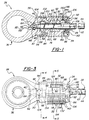
- the second of the two preferred embodiments is the "terminal-adjust" embodiment shown at 26 in FIGS. 7 and 8 .
- the terminal-adjust embodiment is identical to the cable-adjust embodiment except that the terminal-adjust embodiment includes a terminal 36 integrally extending from the elongated member 28 rather than the housing means 30 .
- the end of the elongated member 28 opposite the terminal 36 is inserted into the housing means 30 .
- This second embodiment has cable attachment means 38 extending axially from the end of the housing means 30 opposite the elongated member 28 for attaching the core element 14 .
- the adjustment means 26 adjusts the length of the conduit 12, rather than the length of the core element 14 .
- This embodiment is generally shown at 26 in FIG. 14 .
- the housing means 30 and elongated member 28 have bores 40, 40' through which a core element 14 extends.
- the bore 40' through the elongated member 28 extends axially from one end of the elongated member 28 to the other.
- the bore 40 through the housing means 30 extends axially from the tip of the elongated member 28 through the end of the housing means 30 opposite the inserted elongated member 28 .
- the elongated member 28 is formed from a flatted round steel and zinc plated rod indicated at in FIGS. 1-8 .
- the elongated member 28 includes a first end 42 for insertion into a bore 40 in the housing means 30 and a second end 44 for fastening the elongated member 28 to a device to be remotely controlled (not shown), a cable 14, or a conduit 12 .
- the first end 42 of the elongated member 28 comprises a stopper 46, cylindrical section 48 and engagement section 50 .
- the stopper 46 and engagement 50 sections have generally identical cross sectional shapes and sizes. However, in other embodiments, the stopper 46 and engagement 50 sections may have different cross sectional shapes and sizes. As shown in FIG.
- the stopper 46 and engagement 50 sections have opposing arcuate sides 52, 54 respectively.
- the arcuate sides 52, 54 are spaced 180 degrees apart from the centerline of one side to the centerline of the other side.
- the diameter 56 of the cylindrical section 48 is smaller than the cross sectional width or diameter 58 of the stopper 46 and engagement 50 sections.
- the arcuate sides 52, 54 of the engagement section 50 have evenly spaced threads 60 oriented perpendicular to the longitudinal axis 62 of the elongated member 28 .
- the stopper 46 section is flat at its distal end 64 with a beveled circumferential leading edge 66 .
- the locking means shown at 32 in FIGS. 1-8 and 12, is formed from steel or zinc and includes a ring member 68 and a button member 70 .
- the button member 70 is fixed to the ring member 68 and protrudes radially outwardly from the ring member 68 .
- the locking means 32 is rotatably disposed within the housing means 30 and is fixed against axial movement within the housing.
- the ring member shown at 68 in FIGS. 5 and 6, has an interior circumference 72 with threaded portions 74 spaced 180 degrees apart around the interior circumference 72 .
- the threads in the threaded portions 74 are oriented perpendicular to the annular axis 62 of the ring member 68 .
- the threaded portions 74 are for meshing with the evenly-spaced threads 60 on the arcuate sides 52, 54 of the engagement section 50 of the elongated member 28 in the locked position.
- the interior circumference 72 of the ring member 68 defines a circular opening 75, best shown in FIG 20, disposed concentric with the bore 40 of the housing means 30 so as to allow translatory axial movement of the elongated member 28 through the ring member 68 and to allow the elongated member 28 to threadedly engage the ring member 68 through circumferential alignment of the threaded portions 74 of the ring member 68 with the threaded portions 52, 54 of the elongated member 28 .
- the elongated member 28 also prevents the removal of the locking means 32 from the housing means 30 .
- the housing means 30, generally indicated at 30 in FIGS. 1-3, 7, 8 and 12, has an external circumference 78, a bore 40, a receiving end 80, a first end 82 opposite the receiving end 80, and an exterior ledge 84 disposed around the external circumference 78 of the housing means 30 at the approximate mid-point between the first end 82 and the receiving end 80 .
- the ledge 84 need not be at the mid-point.
- the housing means 30 has a generally cylindrical shape and is composed of a hard substance such as plastic or metal.
- the housing means 30 has one of two external shapes depending on which preferred embodiment the housing means 30 is incorporated into.
- the housing means 30 extends integrally and radially from a ring-shaped terminal assembly, generally indicated at 36, having approximately twice the outside diameter of the housing means 30 .
- the housing means 30 has a constant diameter from its receiving end 80 to a point approximately 3/5 the longitudinal distance from its receiving end 80 to the point where the housing means 30 joins the terminal assembly 36, although other proportions would be acceptable. At this point the diameter of the housing means 30 decreases by approximately 5% forming the outer circumferential exterior "ledge" 84 as shown in FIGS. 1, 2, 3, 7, 8 and 14 .
- the smaller-diameter first end 82 of the housing means 30 integrally joins with the terminal assembly 36 .
- the external shape of the housing means 30 is identical to that of the housing means 30 in the cable-adjust embodiment of FIGS. 1, 2 and 3 from the cable-adjust embodiment's receiving end 80 to the point where the first end 82 of the housing means 30 would integrally join the terminal assembly 36 .
- the first end 82 of the housing means 30 does not integrally join the terminal assembly 36 but instead tapers to a third cylindrical-shaped section 38 of even smaller diameter.
- This final section 38, at the first end 82 of the housing means 30, encases and fixedly retains the end of the core element 14, or cable 14 .
- the core element 14 or cable 14 protrudes longitudinally from the first end 82 of the housing means 30 .
- the housing means 30 has a bore 40 for receiving the elongated member 28 .
- the bore 40 extends along the longitudinal axis 62 of the housing means 30 from the receiving end 80 to the first end 82 of the housing means 30 .
- the bore 40 has a cross-sectional shape substantially identical to the cross-sectional shape of the elongated member 28 except that it is slightly larger.
- the bore 40 is only slightly larger to allow sufficient clearance for axial translatory movement of the elongated member 28 while preventing rotational movement relative to the housing means 30 .
- Surrounding the bore 40 opening at the receiving end 80 of the housing means 30 and extending axially from the housing means 30 is a spring location collar 86 .
- the collar 86 extends an axial distance approximately equal to 1/5 the diameter of the bore 40 .
- the thickness of the collar 86 is also approximately 1/5 the diameter of the bore 40 .
- the housing means 30 has a first internal cylindrical cavity 88, concentric with its bore 40, for encasing and allowing the ring member 68 to rotate about the elongated member 28 .
- the interior shape of the first cylindrical cavity 88 is exactly the same as the exterior shape of the ring member 68 except that it is slightly larger in both length and diameter.
- the interior shape of the first cylindrical cavity 88 is sufficiently larger to provide clearance for rotational movement of the ring member 68 within.
- the housing means 30 has an aperture, shown at 90 in FIGS. 3, 5, and 6, extending through the housing means 30 to the first internal cylindrical cavity 88 .
- the aperture 90 is large enough to allow an assembler to insert the ring member 68 into the first cylindrical cavity 88 in the housing means 30 .
- the aperture 90 also allows the button member 70 of the locking means 32 to protrude from the housing means 30 and allows an operator to rotate the ring member 68, within an approximate 90° arc, between its locked and unlocked positions, from outside the housing means 30 .
- the aperture 90 is a generally rectangular window, cut or formed through the housing means 30 and into the first cylindrical cavity 88 so as to restrict the button member 70 to approximately 90° of rotation between the locked and unlocked positions.
- the latching means 34 includes a cover 92 generally indicated in FIGS. 1-14 .
- the cover 92 slidably surrounds a portion of the housing means 30 and is constructed of plastic or metal.
- the cover 92 has the general shape of an open-ended canister with its inside diameter slightly greater than the largest exterior diameter of the housing means 30 .
- the cover 92 has an open end 94, a closed end 96, an internal circumference 98 and a ramped interior ledge 100 disposed around the internal circumference 98 adjacent the open end 94 .
- the ramped ledge 100 has a ramped circumferential portion 102 which begins at the rim 104 formed at the open end 94 of the cover 92 .
- the ramped portion 102 extends inward from the rim 104 a distance approximately equal to 1/4 the length of the cover 92 . At this point the ramp 102 acutely reverses the direction of its slope and radially widens to form the circumferential interior ledge 100 .
- the closed end 96 of the cover 92 is disposed opposite the open end 94 and has a rounded circumferential corner 106 .
- the closed end 96 also has a hole 108 for receiving the elongated member 28 .
- the hole 108 has the same cross-sectional shape and size as the bore 40 of the housing means 30 .
- the hole 108 is axially aligned with the bore 40 when the cover 92 is slid over the housing means 30 .
- the cover 92 and housing means 30 include antirotation means as shown at 110 in FIGS. 5 and 6 for cooperatively engaging and preventing the cover 92 from rotating relative to the housing means 30 .
- the antirotation means 110 includes a spline 112 disposed axially along the inside of the cover 92, and a mating groove 114 disposed axially along the exterior of the housing means 30 opposite the aperture 90 .
- the spline 112 extends from the closed end 96 to the interior ledge 100 of the cover 92 .
- the groove 114 extends from the receiving end 80 of housing means 30 to the exterior ledge 84 of the housing means 30 .
- the cover 92 has an opening 116 disposed over the aperture 90 in the housing means 30 and opposite the spline 112 .
- the opening 116 is generally rectangular in shape with a first side 118 disposed adjacent the open end 94 of the cover 92 .
- the cover 92 has detentes 120, 122 extending from the first side 118 of the opening 116 .
- the detentes 120, 122 engage the button member 70 and hold the locking means 32 in its respective locked and unlocked positions.
- the detentes 120, 122 are spaced apart on the first side 118 of the opening 116 and comprise the inside edges 120, 122 of two rectangular notches 124, 126 cut into the first side 118 of the opening 116 .
- the button member 70 of the locking means 32 extends from the first cylindrical cavity 88 in the housing means 30, through the aperture 90, and through the opening 116 in the cover 92 .
- the button member 70 is generally indicated in FIGS. 18, 19 and 20 and includes a rectangular shaft 130 and a thumb pad 132 .
- the button member 70 is constructed from a hard substance such as metal or plastic.
- the thumb pad shown at 132 in FIG. 20 is formed of metal or plastic in a rectangular arcuate shape.
- the rectangular thumb pad 132 is curved along its length in the shape of a shallow channel.
- the thumb pad 132 has an outer convex surface 134 and an inner concave surface 136 .
- the radius of curvature is constant along the length of the thumb pad 132 to conform to the outer diameter of the cover 92 .
- the thumb pad 132 has a longitudinal axis 138 as shown in FIGS. 18 and 19 .
- the thumb pad 132 is oriented on the cover 92 such that the longitudinal axis 138 of the thumb pad 132 is parallel to the longitudinal axis 62 of the housing means 30 .
- the rectangular shaft 130 is formed integrally with the thumb pad 132 and extends perpendicularly from the concave side 136 of the thumb pad 132 .
- the rectangular shaft 130 is integrally joined to the ring member 68 such that is extends radially from the ring member 68 .
- the width of the rectangular shaft 130 is approximately the same as the thickness of the ring member 68 .
- the thickness of the rectangular shaft 130 is approximately one-third its width.
- the rectangular shaft 130 is long enough to place the thumb pad 132 outside the cover 92 with sufficient clearance to slide over the cover 92 .
- the rectangular notches 124, 126 in the opening 116 in the cover 92 are slightly wider than the width of the rectangular shaft 130 .
- the thumb pad 132 provides a surface area for an operator to apply rotational force and move the locking means 32 between its locked and unlocked positions.
- the outer surface 134 of the thumb pad 132 has longitudinal ridges 140 to more positively engage the surface of an operator's thumb (not shown). This configuration requires an operator to first unlatch the button member 70 by sliding the cover 92 toward the first end 82 of the housing means 30 before the operator can move the locking means 32 out of its locked or unlocked positions.
- the latching means 34 includes a tapered, helical wire spring generally indicated at 142 in FIGS. 1, 2, 8, 12, 15, 16 and 17 .
- the spring 142 forcibly urges the first side 118 of the opening 116 in the cover 92 into contact with the rectangular shaft 130 of the button member 70 on the locking means 32 .
- the spring 142 and cover 92 thus cooperate to hold the locking means 32 in either of its locked and unlocked positions when the button member 70 is aligned with one of the rectangular notches 124, 126 in the first side 118 of the opening 116 .
- the spring 142 is disposed between the closed end 96 of the cover 92 and the receiving end 80 of the housing means 30 .
- the end of the tapered spring 142 having the smaller diameter 144 is seated surrounding the collar 86 integrally extending from around the bore 40 in the housing means 30 .
- the spring 142 provides compressional resistance to movement of the cover 92 away from engagement with the button member 70 of the locking means 32 . In other words, an operator must forcibly move the cover 92 against the longitudinal compressive force of the spring 142 to disengage the rectangular shaft 130 of the button member 70 from the rectangular notches 124, 126 in the opening 116 in the cover 92 .
- the spring 142 also exerts a torsional force on the locking means 32 that urges the locking means 32 toward its locked position.
- the housing means 30 has a small bore 150 in the receiving end 80 for retaining the first leg 146 .
- the small bore 150 (FIGS. 1 and 2 ) is parallel to the longitudinal axis of the housing means 30 .
- the second leg 148 rests with torsional force against the rectangular shaft 130 of the button member 70 .
- This configuration allows an operator to insert the elongated member 28 into the housing means 30, then lock the elongated member 28 in position by pressing against the closed end 96 of the cover 92 and causing the latching means 34 to release the locking means 32 .
- the locking means 32 then snaps into its locked position.
- the operator does not have to push or pull on the elongated member 28 .
- the elongated member 28 finds its own position. In a tight assembly area, an operator may do this with one hand by using his or her thumb to press against the cover 92 while grasping and inserting the elongated member 28 with the remaining fingers of the same hand.
- the spring 142 does not exert a torsional force on the locking means 32 that urges the locking means 32 toward its locked position.
- the configuration of the opening 116 in the cover 92 as used on this "no-torsion version" of the adjustment means 26 is slightly different than the opening 116 in the "torsion version" described above.
- the notches 124, 126 in the opening 116 include a first notch 124 including a first detente 120 for holding the button member 70 in the locked position and a second notch 126 including a second detente 122 for holding the button member 70 in the unlocked position.
- the detentes 120, 122 are spaced apart on the first side 118 of the opening 116 and comprise the inside edges of rectangular notches 124, 126 cut into the first side 118 of the opening 116 .
- the first side 118 of the opening 116 extends diagonally from the corner of the first rectangular notch 124 to the corner of the second rectangular notch 126 .
- the corner of the second rectangular notch is closer to the open end 94 of the cover 92 .
- the diagonally-cut first side 118 of the opening 116 essentially creates a ramp 128 between the deeper first rectangular notch 124 and the shallower second rectangular notch 126 .
- This arrangement requires less initial spring 142 compression to move the button member 70 out of the unlocked position, and requires greater spring 142 compression to move the button member 70 out of the locked position. In other words, this configuration makes the adjustment means 26 easier to lock than to unlock.
- This "no-torsion" alternative embodiment is applicable to any one of the adjustment configurations of FIGS. 1, 8 or 14 .
- the adjusting means includes retaining means, shown at 152 in FIGS. 1, 2, 8 and 14, for slidably retaining the first end 42 of the elongated member 28 within the housing means 30 .
- the retaining means 152 includes a second cylindrical cavity 154 in the housing means 30 ; the stopper 46 , cylindrical 48 and engagement 50 sections of the elongated member 28 ; and a retainer ring 156 .
- the housing means 30 has a second cylindrical cavity 154 with axially opposing ends 158 .
- the second cylindrical cavity 154 is concentric with the bore 40 of the housing means 30 .
- the second cylindrical cavity 154 is disposed between the first cylindrical cavity 88 and the first end 82 of the housing means 30 .
- This second cavity 154 receives and allows axial translatory motion of the first end 42 of the elongated member 28 and the retainer ring 156 .
- the housing means 30 also has a rectangular access window, shown at 160 in FIG. 4 , extending through the housing means 30 to the second cylindrical cavity 154 .
- This access window 160 allows an operator to have access to the retaining means 152 . Once the cover 92 is snapped in place, it covers this access window 160 .
- the cylindrical section 48 of the elongated member 28 has a cross-sectional size smaller than that of the stopper 46 and the engagement 50 sections.
- the retainer ring 156 is a washer that slidably surrounds the cylindrical section 48 .
- the washer has an inner diameter larger than that of the cylindrical section 48 and smaller than that of the stopper 46 and engagement 50 sections.
- the washer has an outside diameter larger than the bore 40 of the housing means 30 and smaller than the diameter of the second cylindrical cavity 154 .
Landscapes
- Engineering & Computer Science (AREA)
- General Engineering & Computer Science (AREA)
- Health & Medical Sciences (AREA)
- Oral & Maxillofacial Surgery (AREA)
- Mechanical Engineering (AREA)
- Flexible Shafts (AREA)
- Selective Calling Equipment (AREA)
Applications Claiming Priority (2)
| Application Number | Priority Date | Filing Date | Title |
|---|---|---|---|
| US08/123,330 US5435203A (en) | 1993-09-16 | 1993-09-16 | Manual shift twist adjustor |
| US123330 | 1993-09-16 |
Publications (2)
| Publication Number | Publication Date |
|---|---|
| EP0648947A1 true EP0648947A1 (de) | 1995-04-19 |
| EP0648947B1 EP0648947B1 (de) | 1998-08-12 |
Family
ID=22408028
Family Applications (1)
| Application Number | Title | Priority Date | Filing Date |
|---|---|---|---|
| EP94500150A Expired - Lifetime EP0648947B1 (de) | 1993-09-16 | 1994-08-31 | Fernbetätigungsvorrichtung zum Übertragen von Bewegungen |
Country Status (4)
| Country | Link |
|---|---|
| US (1) | US5435203A (de) |
| EP (1) | EP0648947B1 (de) |
| DE (1) | DE69412413T2 (de) |
| ES (1) | ES2121173T3 (de) |
Cited By (1)
| Publication number | Priority date | Publication date | Assignee | Title |
|---|---|---|---|---|
| CN104389891A (zh) * | 2014-11-07 | 2015-03-04 | 宁波汽车软轴软管有限公司 | 自动挡拉线可调安装活动头 |
Families Citing this family (8)
| Publication number | Priority date | Publication date | Assignee | Title |
|---|---|---|---|---|
| US5559718A (en) | 1994-04-28 | 1996-09-24 | Cadence Design Systems, Inc. | System and method for model-based verification of local design rules |
| US5653148A (en) * | 1995-12-15 | 1997-08-05 | Teleflex Incorporated | Conduit shortening adjustment assembly |
| US5724858A (en) * | 1996-05-30 | 1998-03-10 | Teleflex Incorporated | Infinite adjustment for motion transmitting remote control assembly |
| DE19800850B4 (de) * | 1998-01-13 | 2007-09-20 | Teleflex Automotive Germany Gmbh | Längseinsteller auf der Seele eines Betätigungszuges |
| US6913312B2 (en) * | 2000-01-18 | 2005-07-05 | Michael Clary | Articulating chair |
| DE20020039U1 (de) * | 2000-11-25 | 2001-05-10 | United Parts FHS Automobil Systeme GmbH, 37586 Dassel | Längseinsteller mit Lösevorrichtung |
| BRPI0403739A (pt) * | 2004-08-25 | 2006-05-02 | Paolo Paparoni | dispositivo de fixação de terminais de cabos de comando |
| US11959312B2 (en) | 2018-05-08 | 2024-04-16 | Magna Closures Inc. | Vehicular latch bushing with cable interface |
Citations (5)
| Publication number | Priority date | Publication date | Assignee | Title |
|---|---|---|---|---|
| EP0069646A2 (de) * | 1981-07-06 | 1983-01-12 | Allied Corporation | Sperrbare Einstellvorrichtung für Kabel |
| FR2617920A2 (fr) * | 1985-10-25 | 1989-01-13 | Acco Cables Mans | Dispositif de commande mecanique de cable a reglage manuel |
| DE3924533A1 (de) * | 1988-08-24 | 1990-03-01 | Nippon Cable System Inc | Verankerungs- und einstellvorrichtung fuer einen steuerzug |
| EP0475017A2 (de) * | 1990-08-11 | 1992-03-18 | Ford-Werke Aktiengesellschaft | Einstellvorrichtung für Bowdenzüge |
| US5156064A (en) * | 1991-05-21 | 1992-10-20 | Handy & Harman Automotive Group, Inc. | Cable length adjustment device |
Family Cites Families (23)
| Publication number | Priority date | Publication date | Assignee | Title |
|---|---|---|---|---|
| US2869391A (en) * | 1954-07-02 | 1959-01-20 | Arens Controls | Rotary locking control |
| US4193616A (en) * | 1978-05-18 | 1980-03-18 | Dana Corporation | Quick connect fitting |
| US4331041A (en) * | 1980-02-07 | 1982-05-25 | Teleflex Incorporated | Motion transmitting remote control assembly |
| US4669330A (en) * | 1984-10-01 | 1987-06-02 | Ford Motor Company | Cable length adjuster |
| FR2577330B1 (fr) * | 1985-02-13 | 1987-02-20 | Bendix France | Dispositif de commande mecanique a cable a reglage automatique |
| US4833937A (en) * | 1985-04-22 | 1989-05-30 | Shimano Industrial Company Limited | Adjusting device for a control cable for a bicycle |
| US4841806A (en) * | 1985-09-13 | 1989-06-27 | Teleflex Incorporated | Self-adjust mini increment |
| FR2589206B1 (fr) * | 1985-10-25 | 1988-04-08 | Bendix France | Dispositif de commande mecanique a cable a reglage manuel |
| US4869123A (en) * | 1985-11-18 | 1989-09-26 | Ford Motor Company | Cable length self-locking adjustment device |
| US4694706A (en) * | 1986-02-14 | 1987-09-22 | Acco Babcock Inc. | Control cable conduit length adjustment device |
| US4688445A (en) * | 1986-04-21 | 1987-08-25 | Teleflex Incorporated | Remote control balanced adjust system |
| US4798100A (en) * | 1987-09-18 | 1989-01-17 | Babcock Industries Inc. | Automatic adjustment device for cable control systems |
| US4753123A (en) * | 1987-10-14 | 1988-06-28 | Babcock Industries Inc. | Automatic self adjusting cable control device |
| US4854186A (en) * | 1987-12-02 | 1989-08-08 | Kuster & Co. Gmbh | Apparatus for adjusting the length of a bowden cable |
| US4852425A (en) * | 1987-12-28 | 1989-08-01 | Ford Motor Company | Variable length rod assembly having locking adjustment mechanism |
| US4854185A (en) * | 1988-10-17 | 1989-08-08 | Babcock Industries Inc. | Manually operated and locked conduit length adjuster system |
| US5138897A (en) * | 1988-11-23 | 1992-08-18 | Moprod Supra Automotive Limited | Cable adjuster |
| ES2017879A6 (es) * | 1989-12-05 | 1991-03-01 | Pujol & Tarago | Terminal de funda ajustable para cables. |
| US4987793A (en) * | 1990-01-04 | 1991-01-29 | Babcock Industries, Inc. | Cable control system with adjustment device |
| US5156063A (en) * | 1991-04-08 | 1992-10-20 | Teleflex Incorporated | Conduit and core element adjust having sliding collar lock |
| US5161428A (en) * | 1991-04-16 | 1992-11-10 | Teleflex Incorporated | Rotatable slider body |
| US5222411A (en) * | 1991-05-21 | 1993-06-29 | Handy & Harmon Automotive Group | Miniature core adjust device |
| US5142933A (en) * | 1991-05-23 | 1992-09-01 | Teleflex Incorporated | Motion transmitting remote control assembly having conduit length adjuster |
-
1993
- 1993-09-16 US US08/123,330 patent/US5435203A/en not_active Expired - Fee Related
-
1994
- 1994-08-31 EP EP94500150A patent/EP0648947B1/de not_active Expired - Lifetime
- 1994-08-31 DE DE69412413T patent/DE69412413T2/de not_active Expired - Fee Related
- 1994-08-31 ES ES94500150T patent/ES2121173T3/es not_active Expired - Lifetime
Patent Citations (5)
| Publication number | Priority date | Publication date | Assignee | Title |
|---|---|---|---|---|
| EP0069646A2 (de) * | 1981-07-06 | 1983-01-12 | Allied Corporation | Sperrbare Einstellvorrichtung für Kabel |
| FR2617920A2 (fr) * | 1985-10-25 | 1989-01-13 | Acco Cables Mans | Dispositif de commande mecanique de cable a reglage manuel |
| DE3924533A1 (de) * | 1988-08-24 | 1990-03-01 | Nippon Cable System Inc | Verankerungs- und einstellvorrichtung fuer einen steuerzug |
| EP0475017A2 (de) * | 1990-08-11 | 1992-03-18 | Ford-Werke Aktiengesellschaft | Einstellvorrichtung für Bowdenzüge |
| US5156064A (en) * | 1991-05-21 | 1992-10-20 | Handy & Harman Automotive Group, Inc. | Cable length adjustment device |
Cited By (1)
| Publication number | Priority date | Publication date | Assignee | Title |
|---|---|---|---|---|
| CN104389891A (zh) * | 2014-11-07 | 2015-03-04 | 宁波汽车软轴软管有限公司 | 自动挡拉线可调安装活动头 |
Also Published As
| Publication number | Publication date |
|---|---|
| DE69412413D1 (de) | 1998-09-17 |
| EP0648947B1 (de) | 1998-08-12 |
| DE69412413T2 (de) | 1998-12-24 |
| US5435203A (en) | 1995-07-25 |
| ES2121173T3 (es) | 1998-11-16 |
Similar Documents
| Publication | Publication Date | Title |
|---|---|---|
| US5144856A (en) | Adjustable cable sheath terminal | |
| EP1552168B1 (de) | Verankerung für einer führungshülle eines betätigungszuges | |
| EP0648947B1 (de) | Fernbetätigungsvorrichtung zum Übertragen von Bewegungen | |
| US4936161A (en) | Cable length adjuster with push and lock attachment | |
| US5369849A (en) | Cable gripping unit with spring biased jaw segments | |
| US5156063A (en) | Conduit and core element adjust having sliding collar lock | |
| US6849803B1 (en) | Electrical connector | |
| US4753123A (en) | Automatic self adjusting cable control device | |
| US6179347B1 (en) | Snap-action pipe coupling retainer with a rhomboidal cross-section | |
| US3427894A (en) | Remote control assembly | |
| US4625579A (en) | Capped core element terminal | |
| US5076747A (en) | Panel fastener having internal threads and having maximum retaining ring retention capability | |
| US5398566A (en) | Manual adjust having oppositely toothed fitting | |
| US8312788B2 (en) | Slide-and-snap lock assembly | |
| WO2000008715A1 (en) | Conduit and fitting with automatic length adjustment | |
| EP3649712A1 (de) | Kabeldurchführungseinrichtung | |
| EP2404070A1 (de) | Verankerungsvorrichtung für ein übertragungskabel | |
| US6193433B1 (en) | Compensating element for a pulling and pressing rod | |
| US8082820B2 (en) | Fastening system | |
| US3416390A (en) | Control device for locking a shaft against axial translation | |
| US8763492B2 (en) | Multi-piece shifter cable system | |
| KR920010893B1 (ko) | 수동 조정식 코어 터미날 | |
| EP3012472B1 (de) | Leitungslängenanpassungsvorrichtung und zugehöriges Verfahren | |
| EP1190185B1 (de) | Kabelverbinder | |
| EP3284962B1 (de) | Befestigungsvorrichtung eines betätigungskabels mit längenanpassung für ein fahrzeuggetriebe |
Legal Events
| Date | Code | Title | Description |
|---|---|---|---|
| PUAI | Public reference made under article 153(3) epc to a published international application that has entered the european phase |
Free format text: ORIGINAL CODE: 0009012 |
|
| AK | Designated contracting states |
Kind code of ref document: A1 Designated state(s): DE ES FR GB IT SE |
|
| 17P | Request for examination filed |
Effective date: 19950915 |
|
| GRAG | Despatch of communication of intention to grant |
Free format text: ORIGINAL CODE: EPIDOS AGRA |
|
| 17Q | First examination report despatched |
Effective date: 19971023 |
|
| GRAG | Despatch of communication of intention to grant |
Free format text: ORIGINAL CODE: EPIDOS AGRA |
|
| GRAH | Despatch of communication of intention to grant a patent |
Free format text: ORIGINAL CODE: EPIDOS IGRA |
|
| GRAH | Despatch of communication of intention to grant a patent |
Free format text: ORIGINAL CODE: EPIDOS IGRA |
|
| GRAH | Despatch of communication of intention to grant a patent |
Free format text: ORIGINAL CODE: EPIDOS IGRA |
|
| GRAA | (expected) grant |
Free format text: ORIGINAL CODE: 0009210 |
|
| ITF | It: translation for a ep patent filed | ||
| AK | Designated contracting states |
Kind code of ref document: B1 Designated state(s): DE ES FR GB IT SE |
|
| REF | Corresponds to: |
Ref document number: 69412413 Country of ref document: DE Date of ref document: 19980917 |
|
| ET | Fr: translation filed | ||
| PG25 | Lapsed in a contracting state [announced via postgrant information from national office to epo] |
Ref country code: SE Free format text: LAPSE BECAUSE OF FAILURE TO SUBMIT A TRANSLATION OF THE DESCRIPTION OR TO PAY THE FEE WITHIN THE PRESCRIBED TIME-LIMIT Effective date: 19981112 |
|
| REG | Reference to a national code |
Ref country code: ES Ref legal event code: FG2A Ref document number: 2121173 Country of ref document: ES Kind code of ref document: T3 |
|
| PLBE | No opposition filed within time limit |
Free format text: ORIGINAL CODE: 0009261 |
|
| STAA | Information on the status of an ep patent application or granted ep patent |
Free format text: STATUS: NO OPPOSITION FILED WITHIN TIME LIMIT |
|
| 26N | No opposition filed | ||
| PGFP | Annual fee paid to national office [announced via postgrant information from national office to epo] |
Ref country code: GB Payment date: 20010626 Year of fee payment: 8 |
|
| PGFP | Annual fee paid to national office [announced via postgrant information from national office to epo] |
Ref country code: FR Payment date: 20010629 Year of fee payment: 8 |
|
| PGFP | Annual fee paid to national office [announced via postgrant information from national office to epo] |
Ref country code: ES Payment date: 20010709 Year of fee payment: 8 |
|
| PGFP | Annual fee paid to national office [announced via postgrant information from national office to epo] |
Ref country code: DE Payment date: 20010830 Year of fee payment: 8 |
|
| REG | Reference to a national code |
Ref country code: GB Ref legal event code: IF02 |
|
| PG25 | Lapsed in a contracting state [announced via postgrant information from national office to epo] |
Ref country code: GB Free format text: LAPSE BECAUSE OF NON-PAYMENT OF DUE FEES Effective date: 20020831 |
|
| PG25 | Lapsed in a contracting state [announced via postgrant information from national office to epo] |
Ref country code: ES Free format text: LAPSE BECAUSE OF NON-PAYMENT OF DUE FEES Effective date: 20020901 |
|
| PG25 | Lapsed in a contracting state [announced via postgrant information from national office to epo] |
Ref country code: DE Free format text: LAPSE BECAUSE OF NON-PAYMENT OF DUE FEES Effective date: 20030301 |
|
| GBPC | Gb: european patent ceased through non-payment of renewal fee |
Effective date: 20020831 |
|
| PG25 | Lapsed in a contracting state [announced via postgrant information from national office to epo] |
Ref country code: FR Free format text: LAPSE BECAUSE OF NON-PAYMENT OF DUE FEES Effective date: 20030430 |
|
| REG | Reference to a national code |
Ref country code: FR Ref legal event code: ST |
|
| REG | Reference to a national code |
Ref country code: ES Ref legal event code: FD2A Effective date: 20030912 |
|
| PG25 | Lapsed in a contracting state [announced via postgrant information from national office to epo] |
Ref country code: IT Free format text: LAPSE BECAUSE OF NON-PAYMENT OF DUE FEES;WARNING: LAPSES OF ITALIAN PATENTS WITH EFFECTIVE DATE BEFORE 2007 MAY HAVE OCCURRED AT ANY TIME BEFORE 2007. THE CORRECT EFFECTIVE DATE MAY BE DIFFERENT FROM THE ONE RECORDED. Effective date: 20050831 |