EP0649023A1 - Accéléromètre électromécanique - Google Patents
Accéléromètre électromécanique Download PDFInfo
- Publication number
- EP0649023A1 EP0649023A1 EP93118650A EP93118650A EP0649023A1 EP 0649023 A1 EP0649023 A1 EP 0649023A1 EP 93118650 A EP93118650 A EP 93118650A EP 93118650 A EP93118650 A EP 93118650A EP 0649023 A1 EP0649023 A1 EP 0649023A1
- Authority
- EP
- European Patent Office
- Prior art keywords
- spring
- sensor body
- sensor
- sensor according
- housing
- Prior art date
- Legal status (The legal status is an assumption and is not a legal conclusion. Google has not performed a legal analysis and makes no representation as to the accuracy of the status listed.)
- Granted
Links
- 230000001133 acceleration Effects 0.000 claims abstract description 47
- 238000010304 firing Methods 0.000 claims abstract description 17
- 230000005540 biological transmission Effects 0.000 claims description 11
- 230000000694 effects Effects 0.000 claims description 5
- 238000011144 upstream manufacturing Methods 0.000 claims 1
- 230000000452 restraining effect Effects 0.000 abstract 1
- 230000006835 compression Effects 0.000 description 13
- 238000007906 compression Methods 0.000 description 13
- 238000010586 diagram Methods 0.000 description 6
- 230000007423 decrease Effects 0.000 description 3
- 238000006073 displacement reaction Methods 0.000 description 2
- 238000000034 method Methods 0.000 description 2
- 239000004020 conductor Substances 0.000 description 1
- 238000011161 development Methods 0.000 description 1
- 230000018109 developmental process Effects 0.000 description 1
- 238000009413 insulation Methods 0.000 description 1
- 238000009527 percussion Methods 0.000 description 1
- 230000001681 protective effect Effects 0.000 description 1
- 230000035945 sensitivity Effects 0.000 description 1
Images

Classifications
-
- B—PERFORMING OPERATIONS; TRANSPORTING
- B60—VEHICLES IN GENERAL
- B60R—VEHICLES, VEHICLE FITTINGS, OR VEHICLE PARTS, NOT OTHERWISE PROVIDED FOR
- B60R21/00—Arrangements or fittings on vehicles for protecting or preventing injuries to occupants or pedestrians in case of accidents or other traffic risks
- B60R21/02—Occupant safety arrangements or fittings, e.g. crash pads
- B60R21/16—Inflatable occupant restraints or confinements designed to inflate upon impact or impending impact, e.g. air bags
- B60R21/33—Arrangements for non-electric triggering of inflation
-
- G—PHYSICS
- G01—MEASURING; TESTING
- G01P—MEASURING LINEAR OR ANGULAR SPEED, ACCELERATION, DECELERATION, OR SHOCK; INDICATING PRESENCE, ABSENCE, OR DIRECTION, OF MOVEMENT
- G01P15/00—Measuring acceleration; Measuring deceleration; Measuring shock, i.e. sudden change of acceleration
- G01P15/02—Measuring acceleration; Measuring deceleration; Measuring shock, i.e. sudden change of acceleration by making use of inertia forces using solid seismic masses
- G01P15/08—Measuring acceleration; Measuring deceleration; Measuring shock, i.e. sudden change of acceleration by making use of inertia forces using solid seismic masses with conversion into electric or magnetic values
- G01P15/135—Measuring acceleration; Measuring deceleration; Measuring shock, i.e. sudden change of acceleration by making use of inertia forces using solid seismic masses with conversion into electric or magnetic values by making use of contacts which are actuated by a movable inertial mass
Definitions
- the invention relates to an electromechanical acceleration sensor for triggering an occupant restraint system in vehicles, with a sensor body which is guided in a translationally displaceable manner in a housing and which is biased into a rest position by a return spring and can be moved into a release position against its force by the return spring.
- Electronic, electromechanical and mechanical acceleration sensors are known for triggering occupant restraint systems in vehicles, for example belt tensioners for the inflatable protective cushions.
- Electronic sensors are equipped with complex processing circuits that process the signal from an accelerometer and deliver an electrical trigger pulse when the acceleration signal integrated over time exceeds a predetermined threshold value.
- Such an electronic acceleration sensor is characterized by high reproducibility of the triggering behavior and a high degree of security against false triggering due to impacts occurring on the vehicle. However, it can only be realized with great technical effort.
- the sensor body used has to go through a certain actuation stroke against the action of a return spring until the triggering, as a result of which the integrating behavior of an electronic processing circuit can be simulated.
- this actuation stroke must be at least a few millimeters.
- the sensor body is loaded into its rest position by the return spring under such a pretension that it only starts to move at acceleration values that are hardly lower than the average acceleration value at which the triggering should take place if the acceleration continues. In the case of a belt tensioner or airbag system, this average acceleration value is approximately 12 g.
- the invention provides an electromechanical acceleration sensor which is distinguished by a noticeably shorter response time, which is comparable to that of electronic sensors.
- the sensor body is acted upon by an additional spring in the direction of its rest position immediately before it reaches its release position.
- the sensor body therefore already responds to low accelerations, preferably from about 2 g, and, with continued acceleration, reaches the start of the actual actuation stroke at a speed which can be calculated from the product of the effective acceleration and the time required for the distance covered.
- the further movement of the sensor body is now also opposed by the force of the additional spring, the spring force of which is preferably a multiple of the spring force of the return spring.
- the combined spring force of both springs is only overcome if the sensor body has a sufficient pulse and / or a sufficiently high inertia force occurs due to the continuous acceleration. If this condition is not met, there is no tripping and the sensor body is returned to its rest position when the acceleration decreases.
- the movement distance of the sensor body from the rest position to the release position can be dimensioned sufficiently large so that false triggers due to impacts are avoided.
- the time period between the occurrence of high acceleration values leading to the triggering and the reaching of the trigger position is noticeably shorter than in conventional electromechanical acceleration sensors.
- the sensor body actuates an electrical contact pair.
- the sensor body releases a spring-loaded firing pin for an impact detonator.
- a parallelepiped-shaped or also cylindrical sensor body 12 is arranged in a cuboid housing 10 so as to be translationally displaceable.
- the sensor body 12 is supported on its end face facing one end of the housing 10 on stops 14 of the housing.
- a actuating plunger 16 is attached to the opposite end face of the sensor body 10.
- a restoring spring 18 is also supported on this end face and is supported at the opposite end on an annular support wall 20 which projects into the interior of the housing 10.
- the support wall 20 On its side facing away from the sensor body 12, the support wall 20 forms a stop for a generally disk-shaped transmission body 22, which is pressed against the support wall by a compression spring 24.
- This additional compression spring 24 is also designed as a helical spring and is supported between the transmission body 22 and the inner surface of the housing 10 opposite it.
- the transmission body 22 carries a contact pin 26 which, in the rest position shown in FIG. 1, lies opposite the free end of a spring contact 28 at a distance of approximately 0.5 mm.
- the spring contact 28 is inserted with the interposition of insulation 30 through a hole in the wall of the housing 10 and fastened with a pin 32 to which a connecting wire 34 is also fastened.
- Another connecting wire 36 is attached to the housing 10, which consists of an electrically highly conductive material.
- the return spring 18 is dimensioned and is under such a pretension that the sensor body 12 moves under the effect of an acceleration of the housing 10 in the direction indicated by an arrow F in FIG. 1 from the stops 14 against the force of the return spring 18, as soon as the acceleration exceeds a value of about 2 g. If the acceleration continues, the sensor body 12 performs an initial stroke until the free end of the actuating plunger 16 hits the transmission body 22.
- the size of this initial stroke is approximately 2 mm, but can be in the range of approximately 1 to 3 mm, depending on the embodiment.
- the stops 14 can also be made adjustable so that an adjustment is possible. During this initial stroke, there is the relationship shown in the diagram in FIG. 2a between the acceleration occurring and the distance traveled. During the translational displacement of the sensor body 12 until the free end of the actuating plunger 16 abuts the transmission body 22, only the return spring 18 is effective.
- FIG. 2b shows the relationship between the acceleration occurring and the distance when the additional compression spring 24 is effective alone.
- the compression spring 24 is under a prestress about five times higher than the return spring 18, so that a displacement does not occur until the acceleration of more than 10 g.
- both springs are effective when the sensor body 12 moves beyond the point of contact with the transmission body 22, since the Return spring 18 and the compression spring 24 are now functionally connected in parallel.
- the effect of the return spring 18 in combination with the additional compression spring 24 is illustrated in the diagram in FIG. 2. Only the return spring 18 is effective via the initial stroke designated A; on the subsequent actuation stroke B, both springs are effective.
- the shifting of the transmission body 22 therefore only occurs when an acceleration of 12 g is exceeded. If the high acceleration continues, the end face of the contact pin 26 finally hits the free end of the contact spring 28 at the end of the actuation stroke B, thereby generating a trigger signal for an electrical igniter on a pyrotechnic gas generator or the like. If the acceleration does not continue or decrease, the transmission body 22 does not reach this release position, but rather returns to its starting position on the support wall 20. If the acceleration drops further, the sensor mass 12 also returns to its rest position.
- the housing 10 of the acceleration sensor is attached to the body of a vehicle.
- the spring-loaded sensor mass 12 behaves like an integrating member, so that the triggering process can be illustrated in principle by the diagram according to FIG. 2c.
- the trigger criterion is not the exceeding of a certain average acceleration value, but rather the speed of the sensor body at the beginning of the actuation stroke B. If this speed is sufficiently high, contact is made. Otherwise, the sensor body 12 returns to its rest position when the acceleration decreases.
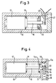
- the embodiment shown in FIG. 3 differs from that of FIG. 1 in that the transmission body is omitted and the additional spring is formed by a spring contact 40 which is clamped on the housing 10 and projects into the interior thereof.
- the contact spring 40 forms the movable contact of a contact pair
- the fixed contact 42 is also clamped on the housing 10 and projects into the interior thereof.
- the distance between these contacts is approximately 0.5 mm and can range from approximately 0.3 to 0.8 mm.
- the free end of the actuating plunger 16 of the sensor mass 12 lies in the rest position of the same at a distance of approximately 2 mm from the opposite surface the contact spring 40.
- the contact spring 40 has a large spring hardness in comparison to the return spring 18, so that the dependence of the distance traveled on the acceleration occurring, as shown in FIG. 2c, is also shown in this embodiment.
- the actuation stroke B begins as soon as the free end of the actuating plunger 16 has come into contact with the contact spring 40 and is completed as soon as the contact spring 40 comes into contact
- the resilience of the contact spring prevents contact bouncing.
- the arrangement and design of the sensor mass 12 with its actuating plunger 16 largely correspond to the embodiment according to FIG. 3, so that there is no renewed description.
- this embodiment is intended for triggering a pyrotechnic gas generator with an impact igniter.
- the impact igniter which is shown only schematically in FIG. 4 and is designated by 50, sits at the end of a bore 52 in the housing 10, which is oriented perpendicular to the axis of the sensor body 12.
- the bore 52 lies between the end wall 10a of the housing 10 facing away from the sensor body 12 and an intermediate wall 21 of the housing which is open towards the free end of the actuating plunger 16.
- a firing pin 54 with play to the inside of the end wall 10a is received in the bore 52.
- a tensioned compression spring 56 is supported between the bottom wall of the bore 52 and the end face of the firing pin 54 opposite this.
- the opposite free end of the firing pin 54 is held at a distance of, for example, about 10 mm from the firing igniter 50.
- the firing pin 54 is also provided with a lateral extension 54a, which lies opposite the free end of the actuating plunger 16 and on which a ramp surface 58 is formed. With this ramp surface 58, the firing pin 54 is supported in the secured position shown in FIG. 4 on a corresponding support surface 60 on the inner edge of the intermediate wall 21.
- the ramp surface 58 and the support surface 60 are inclined at such an angle to the axis of the sensor body 12 that the firing pin 54 is held in abutment on the adjacent surface of the intermediate wall 21 by the axial component, directed towards the sensor body 12, of the force generated by the compression spring 56 becomes.
- the axial extent of the ramp surface 58 is somewhat smaller than the distance between the firing pin 54 and the inside of the end wall 10a, so that the firing pin 54, when it moves beyond the edge of the support surface 60 in the direction of the end wall 10a is released from this support surface 60 and then accelerated by the compression spring 56 in the direction of the percussion fuse 50.
- the sensor body 12 shifts in the direction of the firing pin 54 when the vehicle decelerates under the action of its inertial force, only the return spring 18 is initially effective. As soon as the free end of the actuating plunger 16 strikes the lateral extension 54a of the firing pin 54, in addition to the force of the spring 18, the axial force component which is supported by the compression spring 56 under the action of the support on the support surface 60 must be overcome in addition to the force of the spring 18 Ramp surface 58 is generated.
- the compression spring 56 is dimensioned hard relative to the return spring 18, so that the sum of the effective forces corresponds to the diagram in Fig. 2c. In this embodiment, too, there is no triggering if the pulse of the sensor body 12 does not have a sufficiently large value.
- the firing pin 54 then returns to its secured position in contact with the side surface of the intermediate wall 21.
- the triggering characteristic in particular the dimensioning of the return spring 18, the hardness of the compression spring 56 and the axial extent of the ramp surface 58.
- acceleration sensor With the acceleration sensor according to the invention, surprisingly short tripping times are achieved in comparison to conventional designs, which are comparable to those of electronic tripping systems. Since the sensor mass only responds to accelerations in one direction, the longitudinal direction of the housing 10, there is no sensitivity to transverse accelerations.
Landscapes
- Engineering & Computer Science (AREA)
- Mechanical Engineering (AREA)
- Physics & Mathematics (AREA)
- General Physics & Mathematics (AREA)
- Switches Operated By Changes In Physical Conditions (AREA)
- Air Bags (AREA)
Priority Applications (4)
| Application Number | Priority Date | Filing Date | Title |
|---|---|---|---|
| JP6249590A JP2836777B2 (ja) | 1993-10-15 | 1994-10-14 | 車両乗員拘束装置を起動するための慣性センサ |
| US08/323,342 US5533588A (en) | 1993-10-15 | 1994-10-14 | Mechanical acceleration sensor |
| US08/636,925 US5692580A (en) | 1993-10-15 | 1996-04-24 | Electromechanical acceleration sensor |
| US08/637,205 US5706911A (en) | 1993-10-15 | 1996-04-24 | Electromechanical acceleration sensor |
Applications Claiming Priority (2)
| Application Number | Priority Date | Filing Date | Title |
|---|---|---|---|
| DE4335250 | 1993-10-15 | ||
| DE4335250A DE4335250A1 (de) | 1993-10-15 | 1993-10-15 | Elektromechanischer Beschleunigungssensor |
Publications (2)
| Publication Number | Publication Date |
|---|---|
| EP0649023A1 true EP0649023A1 (fr) | 1995-04-19 |
| EP0649023B1 EP0649023B1 (fr) | 1999-05-12 |
Family
ID=6500276
Family Applications (1)
| Application Number | Title | Priority Date | Filing Date |
|---|---|---|---|
| EP93118650A Expired - Lifetime EP0649023B1 (fr) | 1993-10-15 | 1993-11-19 | Accéléromètre |
Country Status (3)
| Country | Link |
|---|---|
| EP (1) | EP0649023B1 (fr) |
| DE (2) | DE4335250A1 (fr) |
| ES (1) | ES2074407T3 (fr) |
Cited By (1)
| Publication number | Priority date | Publication date | Assignee | Title |
|---|---|---|---|---|
| FR2756378A1 (fr) * | 1996-11-28 | 1998-05-29 | Albert Pascal | Capteur de type a inertie |
Families Citing this family (1)
| Publication number | Priority date | Publication date | Assignee | Title |
|---|---|---|---|---|
| DE19518824C1 (de) * | 1995-05-23 | 1996-08-14 | Schmidt Feinmech | Schalter |
Citations (5)
| Publication number | Priority date | Publication date | Assignee | Title |
|---|---|---|---|---|
| FR2377638A1 (fr) * | 1977-01-13 | 1978-08-11 | Foerenade Fabriksverken | Detecteur de collision |
| GB2236621A (en) * | 1989-10-06 | 1991-04-10 | Breed Automotive Tech | Velocity change sensors |
| US5012050A (en) * | 1990-02-23 | 1991-04-30 | Siemens Automotive Limited | Dual pole switch assembly for an inertia actuated switch |
| EP0466021A2 (fr) * | 1990-07-13 | 1992-01-15 | ddm hopt + schuler GmbH & Co. KG | Interrupteur d'accélération avec lame à action brusque |
| US5217252A (en) * | 1990-04-17 | 1993-06-08 | Kabushiki Kaisha Tokai-Rika-Denki-Seisakusho | Actuator for use in emergency situation of vehicle |
-
1993
- 1993-10-15 DE DE4335250A patent/DE4335250A1/de not_active Withdrawn
- 1993-11-19 ES ES93118650T patent/ES2074407T3/es not_active Expired - Lifetime
- 1993-11-19 EP EP93118650A patent/EP0649023B1/fr not_active Expired - Lifetime
- 1993-11-19 DE DE59309578T patent/DE59309578D1/de not_active Expired - Fee Related
Patent Citations (5)
| Publication number | Priority date | Publication date | Assignee | Title |
|---|---|---|---|---|
| FR2377638A1 (fr) * | 1977-01-13 | 1978-08-11 | Foerenade Fabriksverken | Detecteur de collision |
| GB2236621A (en) * | 1989-10-06 | 1991-04-10 | Breed Automotive Tech | Velocity change sensors |
| US5012050A (en) * | 1990-02-23 | 1991-04-30 | Siemens Automotive Limited | Dual pole switch assembly for an inertia actuated switch |
| US5217252A (en) * | 1990-04-17 | 1993-06-08 | Kabushiki Kaisha Tokai-Rika-Denki-Seisakusho | Actuator for use in emergency situation of vehicle |
| EP0466021A2 (fr) * | 1990-07-13 | 1992-01-15 | ddm hopt + schuler GmbH & Co. KG | Interrupteur d'accélération avec lame à action brusque |
Cited By (1)
| Publication number | Priority date | Publication date | Assignee | Title |
|---|---|---|---|---|
| FR2756378A1 (fr) * | 1996-11-28 | 1998-05-29 | Albert Pascal | Capteur de type a inertie |
Also Published As
| Publication number | Publication date |
|---|---|
| DE59309578D1 (de) | 1999-06-17 |
| ES2074407T3 (es) | 1999-09-16 |
| EP0649023B1 (fr) | 1999-05-12 |
| DE4335250A1 (de) | 1995-04-20 |
| ES2074407T1 (es) | 1995-09-16 |
Similar Documents
| Publication | Publication Date | Title |
|---|---|---|
| DE3015155C2 (de) | Geschwindigkeitsänderungssensor | |
| DE2801426C2 (fr) | ||
| EP0391227B1 (fr) | Capteur d'accélération et de décélération | |
| DE3115630A1 (de) | Geschwindigkeits-aenderungssensor | |
| DE4143032A1 (de) | Gasgedaempfter aufprallsensor | |
| EP0452521B1 (fr) | Mécanisme de déclenchement pour dispositifs tendeurs dans des véhicules | |
| EP1149004B1 (fr) | Procede pour verifier la fonction d'un systeme de commande pour moyens de protection des passagers dans une automobile | |
| EP0689219A2 (fr) | Contacteur mécanique sensible aux mouvements d'un véhicule | |
| DE4400206A1 (de) | Stoßfeststellungseinrichtung | |
| DE4207153A1 (de) | Ausloesevorrichtung fuer eine fahrzeug-sicherheitseinrichtung | |
| DE2426845C2 (de) | Sicherheitseinrichtung für Fahrzeuge | |
| EP0649023B1 (fr) | Accéléromètre | |
| DE3816591C2 (fr) | ||
| DE4031332C2 (de) | Beschleunigungssensor | |
| DE4219473C2 (de) | Mechanischer Aufprallsensor | |
| DE69623638T2 (de) | Vorrichtung zum zünden einer pyrotechnischen treibladung | |
| EP0705742B1 (fr) | Dispositif de déclenchement pour système de retenue pour occupant | |
| DE2803781A1 (de) | Verzoegerungsaufnehmer, insbesondere zur ausloesung von insassen-schutzvorrichtungen im kraftfahrzeug | |
| DE3207216A1 (de) | Ausloesevorrichtung fuer eine insassenschutzvorrichtung | |
| DE2850836C2 (de) | Elektromagnetischer Geber | |
| EP0686526B1 (fr) | Détecteur pour déclencher un allumage en cas de forte décélération d'un véhicule | |
| DE19741537B4 (de) | Zweiachsiger mechanischer Beschleunigungssensor | |
| DE3739440C2 (de) | Insassen-Rückhaltesystem in einem Fahrzeug | |
| DE19503009C2 (de) | Beschleunigungssensor | |
| DE2263250C3 (de) | Kontrollvorrichtung für die Funktion einer Sicherheitseinrichtung für Fahrzeuginsassen |
Legal Events
| Date | Code | Title | Description |
|---|---|---|---|
| PUAI | Public reference made under article 153(3) epc to a published international application that has entered the european phase |
Free format text: ORIGINAL CODE: 0009012 |
|
| AK | Designated contracting states |
Kind code of ref document: A1 Designated state(s): DE ES FR GB IT SE |
|
| ITCL | It: translation for ep claims filed |
Representative=s name: DR. ING. A. RACHELI & C. |
|
| GBC | Gb: translation of claims filed (gb section 78(7)/1977) | ||
| EL | Fr: translation of claims filed | ||
| 17P | Request for examination filed |
Effective date: 19950518 |
|
| REG | Reference to a national code |
Ref country code: ES Ref legal event code: BA2A Ref document number: 2074407 Country of ref document: ES Kind code of ref document: T1 |
|
| RAP1 | Party data changed (applicant data changed or rights of an application transferred) |
Owner name: TRW OCCUPANT RESTRAINT SYSTEMS GMBH |
|
| 17Q | First examination report despatched |
Effective date: 19961017 |
|
| GRAG | Despatch of communication of intention to grant |
Free format text: ORIGINAL CODE: EPIDOS AGRA |
|
| GRAG | Despatch of communication of intention to grant |
Free format text: ORIGINAL CODE: EPIDOS AGRA |
|
| GRAH | Despatch of communication of intention to grant a patent |
Free format text: ORIGINAL CODE: EPIDOS IGRA |
|
| GRAH | Despatch of communication of intention to grant a patent |
Free format text: ORIGINAL CODE: EPIDOS IGRA |
|
| RAP1 | Party data changed (applicant data changed or rights of an application transferred) |
Owner name: TRW OCCUPANT RESTRAINT SYSTEMS GMBH & CO. KG |
|
| GRAA | (expected) grant |
Free format text: ORIGINAL CODE: 0009210 |
|
| AK | Designated contracting states |
Kind code of ref document: B1 Designated state(s): DE ES FR GB IT SE |
|
| REF | Corresponds to: |
Ref document number: 59309578 Country of ref document: DE Date of ref document: 19990617 |
|
| ET | Fr: translation filed | ||
| GBT | Gb: translation of ep patent filed (gb section 77(6)(a)/1977) |
Effective date: 19990621 |
|
| REG | Reference to a national code |
Ref country code: ES Ref legal event code: FG2A Ref document number: 2074407 Country of ref document: ES Kind code of ref document: T3 |
|
| PGFP | Annual fee paid to national office [announced via postgrant information from national office to epo] |
Ref country code: SE Payment date: 19991103 Year of fee payment: 7 |
|
| PLBE | No opposition filed within time limit |
Free format text: ORIGINAL CODE: 0009261 |
|
| STAA | Information on the status of an ep patent application or granted ep patent |
Free format text: STATUS: NO OPPOSITION FILED WITHIN TIME LIMIT |
|
| 26N | No opposition filed | ||
| PGFP | Annual fee paid to national office [announced via postgrant information from national office to epo] |
Ref country code: GB Payment date: 20001004 Year of fee payment: 8 |
|
| PGFP | Annual fee paid to national office [announced via postgrant information from national office to epo] |
Ref country code: FR Payment date: 20001107 Year of fee payment: 8 |
|
| PGFP | Annual fee paid to national office [announced via postgrant information from national office to epo] |
Ref country code: ES Payment date: 20001121 Year of fee payment: 8 |
|
| PG25 | Lapsed in a contracting state [announced via postgrant information from national office to epo] |
Ref country code: SE Free format text: THE PATENT HAS BEEN ANNULLED BY A DECISION OF A NATIONAL AUTHORITY Effective date: 20001129 |
|
| EUG | Se: european patent has lapsed |
Ref document number: 93118650.6 |
|
| PG25 | Lapsed in a contracting state [announced via postgrant information from national office to epo] |
Ref country code: GB Free format text: LAPSE BECAUSE OF NON-PAYMENT OF DUE FEES Effective date: 20011119 |
|
| PG25 | Lapsed in a contracting state [announced via postgrant information from national office to epo] |
Ref country code: ES Free format text: LAPSE BECAUSE OF NON-PAYMENT OF DUE FEES Effective date: 20011120 |
|
| REG | Reference to a national code |
Ref country code: GB Ref legal event code: IF02 |
|
| GBPC | Gb: european patent ceased through non-payment of renewal fee |
Effective date: 20011119 |
|
| PG25 | Lapsed in a contracting state [announced via postgrant information from national office to epo] |
Ref country code: FR Free format text: LAPSE BECAUSE OF NON-PAYMENT OF DUE FEES Effective date: 20020730 |
|
| REG | Reference to a national code |
Ref country code: FR Ref legal event code: ST |
|
| REG | Reference to a national code |
Ref country code: FR Ref legal event code: ST |
|
| PGFP | Annual fee paid to national office [announced via postgrant information from national office to epo] |
Ref country code: DE Payment date: 20031128 Year of fee payment: 11 |
|
| REG | Reference to a national code |
Ref country code: ES Ref legal event code: FD2A Effective date: 20021213 |
|
| PG25 | Lapsed in a contracting state [announced via postgrant information from national office to epo] |
Ref country code: DE Free format text: LAPSE BECAUSE OF NON-PAYMENT OF DUE FEES Effective date: 20050601 |
|
| PG25 | Lapsed in a contracting state [announced via postgrant information from national office to epo] |
Ref country code: IT Free format text: LAPSE BECAUSE OF NON-PAYMENT OF DUE FEES;WARNING: LAPSES OF ITALIAN PATENTS WITH EFFECTIVE DATE BEFORE 2007 MAY HAVE OCCURRED AT ANY TIME BEFORE 2007. THE CORRECT EFFECTIVE DATE MAY BE DIFFERENT FROM THE ONE RECORDED. Effective date: 20051119 |