EP0649029A2 - Dispositif de localisation et d'identification de surintensités - Google Patents
Dispositif de localisation et d'identification de surintensités Download PDFInfo
- Publication number
- EP0649029A2 EP0649029A2 EP94116471A EP94116471A EP0649029A2 EP 0649029 A2 EP0649029 A2 EP 0649029A2 EP 94116471 A EP94116471 A EP 94116471A EP 94116471 A EP94116471 A EP 94116471A EP 0649029 A2 EP0649029 A2 EP 0649029A2
- Authority
- EP
- European Patent Office
- Prior art keywords
- surge
- discriminating
- digital signal
- accordance
- wave form
- Prior art date
- Legal status (The legal status is an assumption and is not a legal conclusion. Google has not performed a legal analysis and makes no representation as to the accuracy of the status listed.)
- Granted
Links
Images


Classifications
-
- G—PHYSICS
- G01—MEASURING; TESTING
- G01R—MEASURING ELECTRIC VARIABLES; MEASURING MAGNETIC VARIABLES
- G01R31/00—Arrangements for testing electric properties; Arrangements for locating electric faults; Arrangements for electrical testing characterised by what is being tested not provided for elsewhere
- G01R31/08—Locating faults in cables, transmission lines, or networks
- G01R31/088—Aspects of digital computing
Definitions
- the present invention relates to a surge discriminating and locating system for detecting the characteristics of the waveform of a surge occurring on a power transmission line to determine whether the surge is due to lightning flashover, including back flashover and direct strike, to inductive strike, or AC fault, including grounding and short circuit, so as to locate not only the point where the fault occurred but also the point where the inductive strike occurred and to discriminate the characteristics thereof.
- the kind of fault is detected by a protective relay provided in the substation separately from the fault locating system.
- Information based on the detection by the protective relay is displayed by a display unit near the protective relay in the substation or is transferred via the communication network to the sites where the information is required.
- the sites are provided with the information, they require by a phone call from a person at the substation or the like. As a result, the sites often do not receive the information promptly, which is likely to delay the start of the restoration work.
- the protective relay must be of large capacity and is subject to extremely large loads. What is more, it can not detect inductive strikes.
- a surge discriminating and locating system having at least one master station and at least one slave station, comprises surge receiving means for receiving surges which occur on a power transmission line, locating means for locating a point where the surge occurs, digitizing means for digitizing said surge into a digital signal, extraction means for extracting from said digital signal the characterized portions thereof as information representative of the surge wave form, memory means for storing predetermined reference information concerning surge characteristics, and discriminating means for comparing said information representative of the surge wave form with said reference information stored in said memory means to discriminate the kind of surge.
- At least one of said master station and said slave station comprises display means for providing a display based on said digital signal.
- said one of said master station and said slave station further comprises second memory means for storing said digital signal.
- said extracting means is configured to extract from said digital signal a peak value of the surge as said information representative of said surge wave form.
- said extracting means is configured to extract from said digital signal a rise time of the surge as said information representative of said surge wave form.
- said extracting means is configured to extract from said digital signal information on the existence of a prestrike as said information representative of said surge wave form.
- said locating means includes a GPS receiver for receiving radio Waves from a space satellite to provide periodic pulses and reset signals in accordance with said radio waves, counter means which is periodically reset by said reset signals, and converts said periodic pulses into a binary code signal to determine a time when the surge arrived at the station concerned in accordance with an output of said surge receiving means, wherein said slave station further comprises transmitting means for transmitting a value of said counter means to said master station, and wherein said master station further comprises receiving means for receiving said value of said transmitting means of said slave station, and is adapted to compare said value transmitted from said slave station with said value from said counter means of said master station to locate the point where the surge occurred.
- a surge discriminating system comprises, surge receiving means for receiving surges which occur on a power transmission line, digitizing means for digitizing a surge into digital signals, extraction means for extracting from said digital signals the characterized portions thereof as information representative of the surge wave form, memory means for storing predetermined reference information concerning surge characteristics, and discriminating means for comparing said information representative of said surge wave form with said reference information stored in said memory means to discriminate the kind of surge.
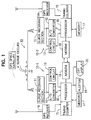
- a surge discriminating and locating system which is an embodiment of the present invention comprises a master station 10-1 and a slave station 10-2.
- the master station 10-1 comprises a surge receiving section 11 for receiving high-voltage surge signals transmitted along a power transmission line and transforming each surge signal into a signal of a level receivable by a low-voltage circuit, e.g.
- a transistor-transistor logic (TTL) circuit for sampling the signal of the predetermined level transformed by the surge receiving section 11 at a high speed and for digitizing it into a digital signal for delivering to a processor 16, a control circuit 13 for setting a trigger level and for controlling a triggering timing or the like, a GPS receiver 14 for receiving information from a global positioning system (GPS) space satellite to supply to a timing counter 15 periodic pulses at intervals of 10 nsec to 100 nsec, namely, pulses of 100 MHz to 10 MHz and reset signals at intervals of 1 second, the timing counter 15 which is adapted to be reset by the reset signals from the GPS receiver 14 and to transform the periodic pulses of 100 MHz to 10 MHz into digital signals such as binary codes, the processor 16 for comparing the signals transformed by the timing counter 15 of the master station 10-1 and the slave station 10-2 into digital values to determine the distance from the master station 10-1 to the point on the power transmission line where the surge occurred, for discrimin
- the output devices include a digital plotter 19, a CRT display 20, and the like for reproducing the wave form of the surge and for outputting the distance from the master station 10-1 to the point where the surge occurred.
- the memory 17 of the master station 10-1 further stores reference information concerning the nature of surges in a predetermined area thereof in advance.
- the slave station 10-2 comprises a surge receiving section 11, an A/D converter 12, a control circuit 13, a GPS receiver 14, a timing counter 15, a processor 16, a memory 17, and a modem 18.
- the modem 18 of the slave station 10-2 functions as a data transmitter for transmitting data to the modem 18 of the master station 10-1.
- a surge When a surge occurs on the power transmission line, it is received by the surge receiving section 11 and is transformed into a signal of predetermined voltage level.
- the signal of the predetermined voltage level is delivered to the control circuit 13 and compared with a predetermined signal of a threshold level. If the level of the signal is over the threshold level, a surge detection signal is delivered to the processor 16.
- the signal of the predetermined level are also is delivered to the A/D converter 12 to be converted into a digital signal. In accordance with the control by the processor 16, the digital signal is stored in the predetermined area of the memory 17.
- the processor 16 determines the time when the surge arrived at the station 10-1 or 10-2. This is accomplished by use of the timing counter 15 which operates in synchronism with the information received by the GPS receiver 14 from the GPS space satellite. Namely, the processor 16 reads out the value of the timing counter 15 when it receives the surge detecting signal from the control circuit 13, and temporarily stores the value of the timing counter 15 in the memory 17. Then, the processor 16 of the slave station 10-2 transmits the value similarly stored temporarily in its memory 17 via the modem 18. The processor 16 of the master station 10-1 calculates the difference between the counter value when the surge arrived at the master station 10-1 and that when it arrived at the slave station 10-2. In accordance with the difference, it is possible to accurately locate the point where the surge occurred. This method is disclosed by the U.S.P. No. 5,070,537, which is incorporated herein by reference.
- each kind of surge is characterized by its peak value, rise time and the like. Accordingly, the present invention discriminates the kind of surge by extracting such characteristics from the surge.
- the processor 16 of the master station 10-1 extracts from the digital signal output by the A/D converter 12 the characterized portions thereof as data characteristic of the surge wave form.
- the processor 16 extracts the peak value, rise time, and information indicating whether or not prestrike is present.
- the peak value is the magnitude between minimum value and maximum value of the surge.
- the processor 16 calculates the difference between the minimum and maximum values of the digital signal and converts it into the real peak value.
- the rise time is the time during which the value of the surge increases from 10 % to 90 % of the maximum value. Prestrike refers to slight variations in voltage before the surge pulse occurs.
- the processor 16 compares the data characteristic of the surge wave form and the reference data characteristic of surge wave forms stored in the memory 17 in advance to discriminate the kind of surge in accordance with logic for the discrimination.
- the reference data characteristic of the surge wave forms include reference data representative of the peak value, and of the rise time, and the data indicating whether or not prestrike is present.
- the reference data representative of the peak value and those representative of the rise time are appropriately determined in advance based on the characteristics of the surges shown in Table 1, and in due consideration of the loads of various electric circuits connected to the power transmission line.
- Figure 2 is a flow chart showing the process for discriminating the kind of surge in accordance with one embodiment of the present invention.
- the processor 16 reads out the data characteristic of the surge wave form from the memory 17 to determine whether or not prestrike is present (step 101), because the determination of the presence of prestrike enables surge due to lightning to be discriminated from that due to AC fault.
- the data representative of the rise time of the data characteristic of the surge wave form is compared with the reference data representative of the rise time stored in memory 17 in advance (step 102). If the former is less than the latter, then the data representative of the peak value is compared with the reference data representative of the peak value (step 103). If the former is greater than the latter, the surge is determined to be a surge due to lightning such as back flashover or strike flashover (step 104). After the determination, the processor 16 conducts the processing for locating the point where the surge occurred (step 104). Then, the processor 16 delivers the data representative of the kind of surge and the point where the surge occurred to output devices such as the plotter 19 and the CRT display 20.
- the processor 16 does not discriminate the kind of surge, but only locates the point where the surge occurred (step 110). After locating the point, the processor 16 delivers the data representative of the point where the surge occurred to the output devices.
- the data representative of the rise time is greater than the reference data representative of the rise time in the step 102, the data representative of the peak value is then compared with the reference data representative thereof (step 105). If the former is less than the latter, the surge is determined to be a surge due to inductive strike (step 106). After the determination, the processor 16 locates the point where the surge occurred (step 106). Then, the processor 16 delivers the data representative of the kind of surge and the point where the surge occurred to the output devices.
- the processor 16 does not discriminate the kind of surge but only locates the point where the surge occurred (step 110). After locating the point, it delivers the data representative of the point where the surge occurred to the output devices.
- the data representative of the rise time is compared with the reference data representative of the rise time (step 107).
- Table 1 it is experimentally known that if a surge is an AC fault surge and is due to a short circuit, it has a peak value of approximately 0.7 times the system voltage.
- a surge due to grounding has a peak value of approximately 0.82 times the system voltage.
- the data representative of the peak value is compared with the data representative of the value of 0.82 times the system voltage (step 108).
- the surge is determined to be an AC fault surge (step 109).
- the processor 16 locates the point where the surge occurred (step 109). Then, the processor 16 delivers the data representative of the kind of surge and the point where the surge occurred to the output devices.
- the processor 16 does not discriminate the kind of surge. In this case, the processor 16 operates to only locate the point where the surge occurred (step 110), and delivers the data representative of the point where the surge occurred to the output devices.
- Table 2 The basic logic used to discriminate the kind of surge in this embodiment is shown in Table 2.
- Table 2 the states corresponding to areas with horizontal lines do not agree with the states of the kind of surge on the basis of experimentally obtained data. However, these states are theoretically possible and the point of occurrence of such surges can be located should they occur.
- FIG. 3 is a flow chart showing the process for discriminating the kind of surge in accordance with another preferred embodiment.
- the voltage corresponding to the peak value is classified into four bands, namely a first band equal to or greater than 500 KV, a second band equal to or greater than 225 KV and less than 500 KV, a third band equal to or greater than 100 KV and less than 225 KV, and a fourth band less than 100 KV, and the processor 16 determines which band the peak value of the surge falls in (step 201).
- the processor 16 determines whether or not prestrike is present (step 202 or 203). If the processor 16 determines that prestrike is present in the step 203, then it determines whether or not the rise time t of the surge is greater than 1 ⁇ sec and is less than 10 ⁇ sec (step 204). If the processor 16 determines that prestrike is present in the step 202, then it determines whether or not the rise time t is greater than 10 ⁇ sec (step 206). On the other hand, if the processor 16 determines that prestrike is not present in the step 202, it then determines whether or not the rise time t is greater than 0.5 ⁇ sec and less than 1 ⁇ sec (step 205).
- the surge is discriminated to be a surge due to the lightning (step 207), discriminated to be an AC fault surge (step 208), or discriminated to be a surge due to the inductive strike (step 209).
- the point where the surge occurred is located.
- the processor 16 can locate the point where the surge occurred (step 210).
- the bands of the peak value and the ranges of the rise time are used as the reference data characteristic of the surge wave forms.
- the data used in this embodiment are set to correspond to the values at the sending end of the power transmission line.
- the data may vary in value in accordance with the characteristics of the devices for receiving the surge from a bus, which is located in the power station yard of the power transmission station, the effect of other power transmission lines, or the like. Consequently, it should be understood that these values can be set so as to match the actual conditions.
- the master station or the slave station converts the surges into a digital signal to extract the characteristic data therefrom, and compares the characteristic data with the reference data so as to discriminate the kind of surge. Furthermore the master station can locate the point where the surge occurred. Consequently, it is possible not only to rapidly discriminate the kind of fault on the power transmission line and to locate the fault point but also to discriminate a surge due to the inductive strike and to locate the point where the inductive strike occurred.
- the fact that an inductive strike can be discriminated by using the power transmission line as a sensor in this way enables the thus obtained result of discrimination to be used for a lightning forecast system and warning system.
- the surge wave converted into a digital signal is stored in the memory, the surge wave form can be displayed on the CRT display 19 or the like at any desired time.
- the system are arranged to both discriminate the kind of surge and locate the point where the surge occurred.
- the system may be arranged only to discriminate the kind of surge.
- each of the master station and the slave station determines the time when the surge arrives thereto based on the information from the GPS space satellite, and the point where the surge occurred is located in accordance with the difference between the above mentioned times.
- a power line carrier return method generally called as a B-type
- a microwave radio carrier return method generally called as a micro B-type
- the peak value, the rise time, and the information indicating whether or not prestrike is present are used as the data characteristics of the surge wave form, other information such as information indicating whether or not the polarity of the surge is present, a half length of the falling time, or the like can be used as the data characteristic thereof.
- the respective means need not necessarily be physical means and arrangements whereby the function of the respective means is accomplished by software fall within the scope of the present invention.
- the function of a single means may be accomplished by two or more physical means and the functions of two or more means may be accomplished by a single physical means.
Landscapes
- Physics & Mathematics (AREA)
- Engineering & Computer Science (AREA)
- Mathematical Physics (AREA)
- Theoretical Computer Science (AREA)
- General Physics & Mathematics (AREA)
- Locating Faults (AREA)
Applications Claiming Priority (3)
| Application Number | Priority Date | Filing Date | Title |
|---|---|---|---|
| JP26123093 | 1993-10-19 | ||
| JP26123093A JP3686430B2 (ja) | 1993-10-19 | 1993-10-19 | 送電線サージ識別・標定システム |
| JP261230/93 | 1993-10-19 |
Publications (3)
| Publication Number | Publication Date |
|---|---|
| EP0649029A2 true EP0649029A2 (fr) | 1995-04-19 |
| EP0649029A3 EP0649029A3 (fr) | 1996-05-22 |
| EP0649029B1 EP0649029B1 (fr) | 2003-04-16 |
Family
ID=17358953
Family Applications (1)
| Application Number | Title | Priority Date | Filing Date |
|---|---|---|---|
| EP94116471A Expired - Lifetime EP0649029B1 (fr) | 1993-10-19 | 1994-10-19 | Dispositif d'identification de surintensités |
Country Status (4)
| Country | Link |
|---|---|
| US (1) | US5508619A (fr) |
| EP (1) | EP0649029B1 (fr) |
| JP (1) | JP3686430B2 (fr) |
| DE (1) | DE69432506T2 (fr) |
Cited By (12)
| Publication number | Priority date | Publication date | Assignee | Title |
|---|---|---|---|---|
| WO1998009177A1 (fr) * | 1996-08-29 | 1998-03-05 | Asea Brown Boveri Ab | Procede de mesure servant a localiser des defauts sur des lignes haute tension a courant continu |
| EP0805355A3 (fr) * | 1996-04-30 | 1999-04-07 | Dipl.-Ing. H. Horstmann GmbH | Procédé et appareil pour déterminer la distance à un défaut de câble |
| EP0926504A3 (fr) * | 1997-12-18 | 2000-03-22 | Tohoku Electric Power Co., Inc. | Dispositif de localisation de surintensités |
| EP1001271A1 (fr) * | 1998-11-12 | 2000-05-17 | Nippon Kouatsu Electric Co., Ltd | Système de localisation de fautes |
| EP1016869A3 (fr) * | 1998-12-28 | 2000-12-27 | Nippon Kouatsu Electric Co., Ltd | Fehlerortsbestimmungssystem |
| WO2001040814A1 (fr) * | 1999-12-06 | 2001-06-07 | Utilx Corporation | Procede d'affichage pour reflectometre |
| ITBO20090193A1 (it) * | 2009-03-27 | 2010-09-28 | Techimp Technologies S A | Dispositivo e procedimento per localizzare scariche parziali. |
| ITBO20090192A1 (it) * | 2009-03-27 | 2010-09-28 | Techimp Technologies S A | Dispositivo e procedimento per localizzare scariche parziali. |
| CN101980050A (zh) * | 2010-09-14 | 2011-02-23 | 浙江省电力公司台州电业局 | 一种便携式输电线路平断面分析仪 |
| WO2011127967A1 (fr) * | 2010-04-13 | 2011-10-20 | Abb Technology Ag | Détermination de l'arrivée d'un signal en défaut |
| EP3798648A1 (fr) * | 2019-09-26 | 2021-03-31 | Electricité de France | Procédé de détermination d'une position d'un précurseur de défaut dans un câble haute tension en fonctionnement |
| CN115441421A (zh) * | 2022-08-18 | 2022-12-06 | 南京磐能电力科技股份有限公司 | 一种基于32点采样装置的浪涌飞点识别系统及方法 |
Families Citing this family (19)
| Publication number | Priority date | Publication date | Assignee | Title |
|---|---|---|---|---|
| US5576625A (en) * | 1994-02-07 | 1996-11-19 | Kabushiki Kaisha Toshiba | Test method and apparatus for testing a protective relay system |
| EP0845110A4 (fr) * | 1995-07-26 | 1999-04-14 | Airborne Res Ass | Systeme pour localiser un eclair |
| US5729144A (en) * | 1996-12-02 | 1998-03-17 | Cummins; Kenneth L. | Systems and methods for determining location of a fault on an electric utility power distribution system |
| NL1005349C2 (nl) * | 1997-02-24 | 1998-08-26 | Kema Nv | Werkwijze en inrichting voor het opsporen en lokaliseren van onregelmatigheden in een diëlectricum. |
| US6047119A (en) * | 1997-06-30 | 2000-04-04 | Metatech Corporation | Method for tracking, analyzing and responding to lightning service interruptions using LCM technology |
| JP3830699B2 (ja) * | 1999-11-11 | 2006-10-04 | 株式会社東芝 | 事故点標定システム |
| DE60127916T2 (de) * | 2000-10-06 | 2008-01-17 | Kabushiki Kaisha Toshiba | Digitales Schutzrelaissystem |
| US7211994B1 (en) * | 2004-10-12 | 2007-05-01 | Federal Network Systems Inc. | Lightning and electro-magnetic pulse location and detection for the discovery of land line location |
| JP4681320B2 (ja) * | 2005-02-23 | 2011-05-11 | 西日本旅客鉄道株式会社 | 故障検出システム,方法,プログラム及びコンピュータ読み取り可能な記録媒体 |
| US7821450B1 (en) * | 2008-05-21 | 2010-10-26 | The United States Of America As Represented By The Secretary Of The Navy | System and method for transmitting GPS signals over a network |
| EP2214390B1 (fr) * | 2009-01-30 | 2013-01-09 | Alcatel Lucent | Procédés de détermination de l'emplacement d'un défaut dans un circuit de transmission câble et systèmes correspondants pour de tels procédés |
| KR101182596B1 (ko) * | 2010-12-28 | 2012-09-18 | 주식회사 성진테크윈 | 서지 보호기 수명 표시 장치 및 방법 |
| US9178755B2 (en) | 2012-11-14 | 2015-11-03 | Telefonaktiebolaget L M Ericsson (Publ) | Time-based link fault localization |
| US9164065B2 (en) * | 2013-03-12 | 2015-10-20 | Telefonaktiebolaget L M Ericsson (Publ) | Automated fault localization in pipelines and electrical power transmission lines |
| JP6150391B2 (ja) * | 2013-08-19 | 2017-06-21 | ニシム電子工業株式会社 | 送電線故障点標定システム |
| CN103472333A (zh) * | 2013-09-16 | 2013-12-25 | 国家电网公司 | 风电并网电能质量综合性能检测方法 |
| JP6310334B2 (ja) * | 2014-06-06 | 2018-04-11 | 九電テクノシステムズ株式会社 | 電力ケーブル又は電気機器の絶縁劣化診断装置及び方法 |
| JP6170022B2 (ja) * | 2014-07-31 | 2017-07-26 | 京セラドキュメントソリューションズ株式会社 | 電子機器管理システム及び電子機器 |
| RU2639715C1 (ru) * | 2016-09-22 | 2017-12-22 | Рустэм Газизович Хузяшев | Способ определения мест повреждений разветвленной воздушной линии электропередачи в виде появления гололёда на проводах |
Family Cites Families (12)
| Publication number | Priority date | Publication date | Assignee | Title |
|---|---|---|---|---|
| US2717992A (en) * | 1951-10-20 | 1955-09-13 | Itt | Transient surge detector |
| US3710239A (en) * | 1970-04-08 | 1973-01-09 | Tokyo Shibaura Electric Co | Highly sensitive fault localization apparatus capable of locating multiple faults along a section of an electric power transmission line |
| US4198599A (en) * | 1978-07-31 | 1980-04-15 | The University Of Arizona Foundation | Gated lightning detection system |
| JPS5663274A (en) * | 1979-10-30 | 1981-05-29 | Toshiba Corp | Fault point locating device |
| US4996473A (en) * | 1986-08-18 | 1991-02-26 | Airborne Research Associates, Inc. | Microburst/windshear warning system |
| JPS63206668A (ja) * | 1987-02-23 | 1988-08-25 | Sumitomo Electric Ind Ltd | 送電線の事故点標定装置 |
| JP2599613B2 (ja) * | 1988-03-24 | 1997-04-09 | 東北電力 株式会社 | 人工衛星を利用した送電線故障点標定システム |
| GB2222688B (en) * | 1988-09-09 | 1992-12-23 | Gen Electric Co Plc | Equipment for and methods of locating the position of a fault on a power transmission line |
| US5138265A (en) * | 1988-11-30 | 1992-08-11 | Sumitomo Electric Industries, Ltd. | Apparatus and system for locating thunderstruck point and faulty point of transmission line |
| US4972290A (en) * | 1989-09-29 | 1990-11-20 | Abb Power T & D Company Inc. | Electric power system with remote monitoring and control of protective relays |
| AT399600B (de) * | 1990-12-28 | 1995-06-26 | Helmut Ing Umgeher | Verfahren zur überwachung einer oder mehrerer, gegebenenfalls vernetzter, elektrischer leitungen |
| JPH05227650A (ja) * | 1992-02-14 | 1993-09-03 | Ngk Insulators Ltd | 雷事故検出装置 |
-
1993
- 1993-10-19 JP JP26123093A patent/JP3686430B2/ja not_active Expired - Lifetime
-
1994
- 1994-10-18 US US08/324,507 patent/US5508619A/en not_active Expired - Lifetime
- 1994-10-19 DE DE69432506T patent/DE69432506T2/de not_active Expired - Lifetime
- 1994-10-19 EP EP94116471A patent/EP0649029B1/fr not_active Expired - Lifetime
Cited By (27)
| Publication number | Priority date | Publication date | Assignee | Title |
|---|---|---|---|---|
| EP0805355A3 (fr) * | 1996-04-30 | 1999-04-07 | Dipl.-Ing. H. Horstmann GmbH | Procédé et appareil pour déterminer la distance à un défaut de câble |
| WO1998009177A1 (fr) * | 1996-08-29 | 1998-03-05 | Asea Brown Boveri Ab | Procede de mesure servant a localiser des defauts sur des lignes haute tension a courant continu |
| EP0926504A3 (fr) * | 1997-12-18 | 2000-03-22 | Tohoku Electric Power Co., Inc. | Dispositif de localisation de surintensités |
| US6259255B1 (en) | 1997-12-18 | 2001-07-10 | Tohoku Electric Power Co., Inc. | Surge locating system of power transmission line and method thereof |
| EP1001271A1 (fr) * | 1998-11-12 | 2000-05-17 | Nippon Kouatsu Electric Co., Ltd | Système de localisation de fautes |
| US6477475B1 (en) | 1998-11-12 | 2002-11-05 | Nippon Kouatsu Electric Co., Ltd. | Fault point location system |
| EP1016869A3 (fr) * | 1998-12-28 | 2000-12-27 | Nippon Kouatsu Electric Co., Ltd | Fehlerortsbestimmungssystem |
| US6597180B1 (en) | 1998-12-28 | 2003-07-22 | Nippon Kouatsu Electric Co., Ltd. | Fault point location system |
| AU769346B2 (en) * | 1998-12-28 | 2004-01-22 | Motokuni Takaoka | Fault point location system |
| WO2001040814A1 (fr) * | 1999-12-06 | 2001-06-07 | Utilx Corporation | Procede d'affichage pour reflectometre |
| US6646451B2 (en) | 1999-12-06 | 2003-11-11 | Utilx Corporation | Time domain reflectometer display method |
| EP1679521A3 (fr) * | 1999-12-06 | 2006-07-26 | Utilx Corporation | Procédé d'affichage pour réflectomètre à domaine de temp |
| ITBO20090193A1 (it) * | 2009-03-27 | 2010-09-28 | Techimp Technologies S A | Dispositivo e procedimento per localizzare scariche parziali. |
| ITBO20090192A1 (it) * | 2009-03-27 | 2010-09-28 | Techimp Technologies S A | Dispositivo e procedimento per localizzare scariche parziali. |
| WO2010109382A1 (fr) * | 2009-03-27 | 2010-09-30 | Techimp Technologies S.A. | Dispositif et procédé pour localiser des décharges partielles |
| WO2010109413A1 (fr) * | 2009-03-27 | 2010-09-30 | Techimp Technologies S.A. | Dispositif et procédé de localisation de décharges partielles |
| US8762081B2 (en) | 2009-03-27 | 2014-06-24 | Techimp Technologies S.R.L. | Device and method for locating partial discharges |
| US8467982B2 (en) | 2009-03-27 | 2013-06-18 | Techimp Technologies S.R.L. | Device and method for locating partial discharges |
| CN102822688A (zh) * | 2010-04-13 | 2012-12-12 | Abb技术有限公司 | 故障波到达确定 |
| WO2011127967A1 (fr) * | 2010-04-13 | 2011-10-20 | Abb Technology Ag | Détermination de l'arrivée d'un signal en défaut |
| US8598887B2 (en) | 2010-04-13 | 2013-12-03 | Abb Technology Ag | Fault wave arrival determination |
| CN102822688B (zh) * | 2010-04-13 | 2015-02-25 | Abb技术有限公司 | 故障波到达确定 |
| CN101980050B (zh) * | 2010-09-14 | 2012-10-03 | 浙江省电力公司台州电业局 | 一种便携式输电线路平断面分析仪 |
| CN101980050A (zh) * | 2010-09-14 | 2011-02-23 | 浙江省电力公司台州电业局 | 一种便携式输电线路平断面分析仪 |
| EP3798648A1 (fr) * | 2019-09-26 | 2021-03-31 | Electricité de France | Procédé de détermination d'une position d'un précurseur de défaut dans un câble haute tension en fonctionnement |
| FR3101426A1 (fr) * | 2019-09-26 | 2021-04-02 | Electricite De France | Procédé de détermination d’une position d’un précurseur de défaut dans un câble haute tension en fonctionnement |
| CN115441421A (zh) * | 2022-08-18 | 2022-12-06 | 南京磐能电力科技股份有限公司 | 一种基于32点采样装置的浪涌飞点识别系统及方法 |
Also Published As
| Publication number | Publication date |
|---|---|
| US5508619A (en) | 1996-04-16 |
| EP0649029A3 (fr) | 1996-05-22 |
| DE69432506T2 (de) | 2003-11-13 |
| JPH07113837A (ja) | 1995-05-02 |
| EP0649029B1 (fr) | 2003-04-16 |
| JP3686430B2 (ja) | 2005-08-24 |
| DE69432506D1 (de) | 2003-05-22 |
Similar Documents
| Publication | Publication Date | Title |
|---|---|---|
| EP0649029A2 (fr) | Dispositif de localisation et d'identification de surintensités | |
| DE68916732T2 (de) | System zur fehlerorterfassung auf einer energieübertragungsleitung mittels satellit. | |
| EP0762667B1 (fr) | Dispositif de mesure du temps de parcours d'un signal dans un système de transmission numérique | |
| US3891811A (en) | Wire pair identification system | |
| US2427523A (en) | Blanking circuit | |
| US3588611A (en) | Transmission line arc detection and location system | |
| SE521970C2 (sv) | Kabel-TV-system som alstrar logiska signaler baserat på jämförelse mellan detekterade energinivåer i systemet och en referenssignal | |
| JP5224727B2 (ja) | Dme地上装置 | |
| US5463423A (en) | Auxiliary video data detector and data slicer | |
| GB1564384A (en) | Generator brush monitor | |
| EP0389754A2 (fr) | Appareil de localisation de station de diffusion dans un réseau local | |
| CN102439476A (zh) | 全保真雷达接收机数字视频的分发与处理 | |
| US3462681A (en) | Fault locating system utilizing narrow bandwidth channel to transmit fault surge arrival times to a master timing location | |
| EP0021472A1 (fr) | Limiteur contre les surtensions pour une ligne à courant fort | |
| US2879454A (en) | Fault responsive protective system for an electric power transmission line | |
| US5087909A (en) | Method and apparatus for radio frequency signal detection | |
| US3312866A (en) | Distance relay actuated phase comparison relaying device | |
| EP0926504B1 (fr) | Dispositif de localisation de surintensités | |
| DE19612437C2 (de) | Abstandsmeßvorrichtung | |
| GB2206761A (en) | Signal detection apparatus | |
| US5446921A (en) | Circuit for detecting noise and producing a squelch signal | |
| US2709784A (en) | Transmission line fault locator | |
| CN113178852B (zh) | 变电站雷电侵入波的绝缘配合方法、装置、设备及介质 | |
| US2830263A (en) | Metal detector | |
| US3981009A (en) | Bernoulli-DeMoivre sliding window friend-accept decider |
Legal Events
| Date | Code | Title | Description |
|---|---|---|---|
| PUAI | Public reference made under article 153(3) epc to a published international application that has entered the european phase |
Free format text: ORIGINAL CODE: 0009012 |
|
| AK | Designated contracting states |
Kind code of ref document: A2 Designated state(s): DE FR GB IT SE |
|
| PUAL | Search report despatched |
Free format text: ORIGINAL CODE: 0009013 |
|
| AK | Designated contracting states |
Kind code of ref document: A3 Designated state(s): DE FR GB IT SE |
|
| 17P | Request for examination filed |
Effective date: 19961114 |
|
| 17Q | First examination report despatched |
Effective date: 19991013 |
|
| GRAH | Despatch of communication of intention to grant a patent |
Free format text: ORIGINAL CODE: EPIDOS IGRA |
|
| RTI1 | Title (correction) |
Free format text: SURGE DISCRIMINATING SYSTEM |
|
| RTI1 | Title (correction) |
Free format text: SURGE DISCRIMINATING SYSTEM |
|
| GRAH | Despatch of communication of intention to grant a patent |
Free format text: ORIGINAL CODE: EPIDOS IGRA |
|
| GRAA | (expected) grant |
Free format text: ORIGINAL CODE: 0009210 |
|
| AK | Designated contracting states |
Designated state(s): DE FR GB IT SE |
|
| REG | Reference to a national code |
Ref country code: GB Ref legal event code: FG4D |
|
| REF | Corresponds to: |
Ref document number: 69432506 Country of ref document: DE Date of ref document: 20030522 Kind code of ref document: P |
|
| REG | Reference to a national code |
Ref country code: SE Ref legal event code: TRGR |
|
| ET | Fr: translation filed | ||
| PLBE | No opposition filed within time limit |
Free format text: ORIGINAL CODE: 0009261 |
|
| STAA | Information on the status of an ep patent application or granted ep patent |
Free format text: STATUS: NO OPPOSITION FILED WITHIN TIME LIMIT |
|
| 26N | No opposition filed |
Effective date: 20040119 |
|
| PGFP | Annual fee paid to national office [announced via postgrant information from national office to epo] |
Ref country code: IT Payment date: 20100922 Year of fee payment: 17 Ref country code: FR Payment date: 20100923 Year of fee payment: 17 |
|
| PGFP | Annual fee paid to national office [announced via postgrant information from national office to epo] |
Ref country code: DE Payment date: 20101029 Year of fee payment: 17 |
|
| PGFP | Annual fee paid to national office [announced via postgrant information from national office to epo] |
Ref country code: SE Payment date: 20101014 Year of fee payment: 17 Ref country code: GB Payment date: 20101013 Year of fee payment: 17 |
|
| GBPC | Gb: european patent ceased through non-payment of renewal fee |
Effective date: 20111019 |
|
| REG | Reference to a national code |
Ref country code: SE Ref legal event code: EUG |
|
| REG | Reference to a national code |
Ref country code: FR Ref legal event code: ST Effective date: 20120629 |
|
| PG25 | Lapsed in a contracting state [announced via postgrant information from national office to epo] |
Ref country code: DE Free format text: LAPSE BECAUSE OF NON-PAYMENT OF DUE FEES Effective date: 20120501 |
|
| REG | Reference to a national code |
Ref country code: DE Ref legal event code: R119 Ref document number: 69432506 Country of ref document: DE Effective date: 20120501 |
|
| PG25 | Lapsed in a contracting state [announced via postgrant information from national office to epo] |
Ref country code: IT Free format text: LAPSE BECAUSE OF NON-PAYMENT OF DUE FEES Effective date: 20111019 Ref country code: FR Free format text: LAPSE BECAUSE OF NON-PAYMENT OF DUE FEES Effective date: 20111102 Ref country code: GB Free format text: LAPSE BECAUSE OF NON-PAYMENT OF DUE FEES Effective date: 20111019 |
|
| PG25 | Lapsed in a contracting state [announced via postgrant information from national office to epo] |
Ref country code: SE Free format text: LAPSE BECAUSE OF NON-PAYMENT OF DUE FEES Effective date: 20111020 |