EP0649559B1 - Dispositif d'essai de materiaux, monte notamment dans un reacteur a eau sous pression - Google Patents
Dispositif d'essai de materiaux, monte notamment dans un reacteur a eau sous pression Download PDFInfo
- Publication number
- EP0649559B1 EP0649559B1 EP94919030A EP94919030A EP0649559B1 EP 0649559 B1 EP0649559 B1 EP 0649559B1 EP 94919030 A EP94919030 A EP 94919030A EP 94919030 A EP94919030 A EP 94919030A EP 0649559 B1 EP0649559 B1 EP 0649559B1
- Authority
- EP
- European Patent Office
- Prior art keywords
- sword
- probe
- tube
- arrangement
- testing
- Prior art date
- Legal status (The legal status is an assumption and is not a legal conclusion. Google has not performed a legal analysis and makes no representation as to the accuracy of the status listed.)
- Expired - Lifetime
Links
- 238000012360 testing method Methods 0.000 title claims abstract description 102
- 239000000463 material Substances 0.000 title claims abstract description 14
- XLYOFNOQVPJJNP-UHFFFAOYSA-N water Substances O XLYOFNOQVPJJNP-UHFFFAOYSA-N 0.000 title abstract description 12
- 239000000523 sample Substances 0.000 claims abstract description 102
- 238000000034 method Methods 0.000 claims abstract description 8
- 239000012530 fluid Substances 0.000 claims description 24
- 238000004140 cleaning Methods 0.000 claims description 17
- 238000003032 molecular docking Methods 0.000 claims description 12
- 238000003780 insertion Methods 0.000 claims description 5
- 230000037431 insertion Effects 0.000 claims description 5
- 238000006073 displacement reaction Methods 0.000 claims description 4
- 230000007547 defect Effects 0.000 description 5
- 238000007689 inspection Methods 0.000 description 3
- 238000005259 measurement Methods 0.000 description 3
- 238000012544 monitoring process Methods 0.000 description 3
- 230000002093 peripheral effect Effects 0.000 description 3
- 238000005452 bending Methods 0.000 description 2
- 230000003028 elevating effect Effects 0.000 description 2
- 239000002184 metal Substances 0.000 description 2
- 239000000725 suspension Substances 0.000 description 2
- 238000012956 testing procedure Methods 0.000 description 2
- 229920000271 Kevlar® Polymers 0.000 description 1
- 238000009825 accumulation Methods 0.000 description 1
- 230000001154 acute effect Effects 0.000 description 1
- 230000003466 anti-cipated effect Effects 0.000 description 1
- 239000004918 carbon fiber reinforced polymer Substances 0.000 description 1
- 238000001514 detection method Methods 0.000 description 1
- 238000005516 engineering process Methods 0.000 description 1
- 231100001261 hazardous Toxicity 0.000 description 1
- 230000001939 inductive effect Effects 0.000 description 1
- 239000004761 kevlar Substances 0.000 description 1
- 239000007788 liquid Substances 0.000 description 1
- 238000012423 maintenance Methods 0.000 description 1
- 239000004033 plastic Substances 0.000 description 1
- 229920003023 plastic Polymers 0.000 description 1
- 230000005855 radiation Effects 0.000 description 1
- 230000002285 radioactive effect Effects 0.000 description 1
- 238000007789 sealing Methods 0.000 description 1
- 238000009966 trimming Methods 0.000 description 1
- 238000012795 verification Methods 0.000 description 1
- 230000000007 visual effect Effects 0.000 description 1
Images




Classifications
-
- G—PHYSICS
- G21—NUCLEAR PHYSICS; NUCLEAR ENGINEERING
- G21C—NUCLEAR REACTORS
- G21C17/00—Monitoring; Testing ; Maintaining
- G21C17/003—Remote inspection of vessels, e.g. pressure vessels
-
- G—PHYSICS
- G21—NUCLEAR PHYSICS; NUCLEAR ENGINEERING
- G21C—NUCLEAR REACTORS
- G21C17/00—Monitoring; Testing ; Maintaining
- G21C17/017—Inspection or maintenance of pipe-lines or tubes in nuclear installations
-
- Y—GENERAL TAGGING OF NEW TECHNOLOGICAL DEVELOPMENTS; GENERAL TAGGING OF CROSS-SECTIONAL TECHNOLOGIES SPANNING OVER SEVERAL SECTIONS OF THE IPC; TECHNICAL SUBJECTS COVERED BY FORMER USPC CROSS-REFERENCE ART COLLECTIONS [XRACs] AND DIGESTS
- Y02—TECHNOLOGIES OR APPLICATIONS FOR MITIGATION OR ADAPTATION AGAINST CLIMATE CHANGE
- Y02E—REDUCTION OF GREENHOUSE GAS [GHG] EMISSIONS, RELATED TO ENERGY GENERATION, TRANSMISSION OR DISTRIBUTION
- Y02E30/00—Energy generation of nuclear origin
- Y02E30/30—Nuclear fission reactors
Definitions
- inspection of a reactor cap is carried out by dismounting the cap with the control rod mechanism from the reactor and place it on a biological concrete shield.
- the occurrence of defects at each lead-through is checked with the aid of a manipulator and by means of eddy current technology, whereby an eddy current probe is inserted into said gap between the sleeve and the tube.
- the eddy current probe is inserted into the gap by means of a thin metal sword, the probe being mounted at the top of the sword.
- the sword is bent past the end-piece of the sleeve and into the gap by means of reels.
- the sword can only be led forwards in the vertical direction because of the flexibility of the sword, and has to be pulled out of the gap before a displacement around the sleeve can be carried out. If defects are detected at one or more lead-throughs with said eddy current testing, the whole control rod mechanism and the lead-through sleeve with its end-piece are dismounted for the lead-through at issue. For the dismounting of the sleeve, the control rod mechanism with the associated sealing means at the top of the lead-through is disassembled, the end-piece is dismounted and the sleeve is pulled out of the tube.
- Fig 1 a pressurized-water reactor cap 1 placed on a biological concrete shield 2.
- lead-throughs 4 in the cap, normally about 60-75, only two thereof being drawn.
- a lead-through consists of a tube 6 passing through the cap 1, which tube is sealingly welded to the cap 1 at its lower surface.
- a sleeve 8 which is essentially coaxial with the tube and which comprises an end-piece, which may be essentially funnel-shaped.
- the lower end surfaces of the sleeves 8 of all the control rod lead-throughs are normally situated in essentially the same plane, as is shown in Fig 1.
- the parts of the sleeves 8 projecting out of each tube 6 have different lengths, depending on where in the cap dome the lead-through in question is situated.
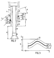
- Fig 2 shows a cut away cap lead-through 4, whereby the thickness B of the cap 1 normally is about 200-250 mm.
- the tube 6 passing the cap 1 is sealingly fastened to the cap by virtue of a pipe weld 16 running around the tube at the lower side of the cap. Between the tube 6 and the cap 1 there is above the weld a narrow first gap 18, hereinafter called a tube gap.
- the tube 6 has normally an outside diameter of about 100 mm and an inside diameter of about 70 mm.
- the lower part of the tube 6 has an inside cone-shaped ending 19, which for convenience hereinafter is called a tube cone.
- the tube cone 19 has a cone angle which is typically a few degrees, e.g. 3°.
- a sleeve 8 which normally has an outside diameter of about 64 mm, comprising an end-piece 9 which in this example is funnel-shaped and which hereinafter also is called a sleeve funnel.
- the sleeve 8 is (not shown) at its upper end sealingly joined to the end of the tube which projects on the upper side of the cap 1. When the control rods are lifted, it is possible to elevate the sleeve to a pivotable position.
- a second gap 20 hereinafter also called sleeve gap, with a nominal gap width of normally about 3 mm.
- the sleeve gap At the upper part of the lead-through there is in the sleeve gap, means to hold the sleeve in a selected position, which can be changed by elevating the sleeve.
- the distance A between the lower end surface of the sleeve 8 and the lower end surface of the tube 6 varies, depending on the position of the lead-through 4 in the dome-shaped cap 1 and due to the fact that the sleeves 8 are arranged in order that the lower end surfaces of all the sleeves 8 be located in essentially the same plane.
- a testing area C is indicated in the axial direction overlapping and around the tube weld 16.
- the area C comprises an area D above the tube weld 16, an area E overlapping the entire tube weld 16 and an area F below the tube weld 16.
- Materials testing over the described area is executed according to the invention by inserting a probe sword into the sleeve gap 20 and by rotating it along the gap around the axis of symmetry of the lead-through.
- the probe sword is then maneuvered in a movement that follows the tube weld 16 and its associated testing area. Since the tube weld 16 follows the intersection between the dome-shaped inner surface of the cap and the tube-shaped outer surface of the tube 6, the testing area unfolded in a plane describes an essentially sinus-shaped stripe 22 according to Fig 3.
- the stripe widths of the testing area have the same designations as in Fig 2, whereby the zero point of said axis is assumed to be situated at the lower end surface of the tube 6.
- a probe sword When a probe sword rotates along the testing area in the sleeve gap 20, it should thus cover the whole width C and follow the stripe 22, and should therefore in the vertical direction have a length of stroke, taken from the end surface of the tube 6, that at the periphery of the cap normally may be about 280 mm.
- the length of stroke is indicated with a G in Figs 2 and 3.
- the probe sword is rotated more than 360° around the sleeve 8, normally about 400°.
- Fig 4 shows as an example a sketch of a preferred embodiment of the inventive testing arrangement 14.
- the testing arrangement 14 is characterized in that it comprises a pinching arrangement 32, by means of which a pinching force may be applied between the outer surface of the tube 6 and the outer surface of the projecting part of the sleeve 8 in order to widen the sleeve gap 20 at one side (cf Fig 2), a sword-guiding arrangement cooperating with a pinching arrangement to guide the sword into the widened part of the gap, a first lifting arrangement for bringing the pinching arrangement on a level with the lower part of the outer tube, a second lifting arrangement for inserting the sword into the gap and a turning arrangement for, in cooperation with the pinching arrangement, displacing the widened part of the gap along the inner periphery of the first tube, whereby the testing arrangement is attachable to said manipulator, and the testing arrangement is dockable at a chosen lead-through by means of the manipulator, whereby the lifting arrangements are arranged at the turning arrangement and where
- the first lifting arrangement of the testing arrangement 14 comprises a central structure 24 which is rotatably attached to a frame 26.
- the frame 26 comprises a turning arrangement comprising a rotational driving unit (not shown) for the central structure 24 and a connection means (not shown) for the connection of control systems which will be further described below.
- a manipulator tool interface 30 is attached to the frame 26, in this embodiment a so-called dovetail, intended to be connected to a corresponding means at the manipulator.
- a frustrum of a cone hereinafter called docking cone 34, which fits against the sleeve funnel 9 and serves as a geometrically locking docking means at the docking of the testing arrangement 14 to a cap lead-through 4.
- a camera At the top of the central structure 24 there is arranged a camera, a lighting means and an aiming means (not shown) for visual support by the maneuvering of the docking.
- a safe centering of the central structure 24 in relation to the axis of the lead-through 4 can be executed by means of the aiming arrangement.
- a fluid-collecting vessel 35 is arranged at the lower part of the central structure 24 for collecting fluid, which during use of the testing arrangement flows down the central structure 24 originating from an accumulation of fluid in a lead-through 4, from cleaning of the sleeve gap and from contact medium in connection with ultrasonic testing.
- the pinching arrangement is built up around the central structure 24, which pinching arrangement is mobile in the vertical direction and is, in its entirety, designated 32.
- the pinching arrangement 32 is detachably attached to the central structure 24 by means of an associated upper fastening means 36 and an associated lower fastening means 38.
- the first lifting arrangement comprises a beam which is vertically displaceable along the central structure 24, here called vertical beam 40, by means of which the pinching arrangement 32, in its entirety, is displaceable in the vertical direction.
- the vertical beam is maneuvered in the vertical direction by means of a vertical beam driving unit 42 and a vertical beam brake 44, whereby the vertical beam driving unit 42 is comprised in the lower fastening means 38 and the vertical beam brake 44 is comprised in the upper fastening means 36.
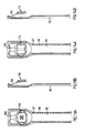
- Fig 5 shows a cross-section of the lower fastening means 38, comprising a remote controllable vertical beam driving unit 42, with which a vertical beam 40 is connected locked by virtue of force and geometry via two vertical bars 41.
- the vertical bars 41 are attached to and runs along the sides of the beam 40.
- the bars are attached to the beam by bolts.
- the lower fastening means 38 comprises a clamping means 46 for, by means of at least one bolt 48, a detachable fastening of the fastening means with the vertical beam driving unit at the central structure 24.
- the vertical beam driving unit 42 is connected to the clamping means by means of at least another bolt 48 and comprises a remote controllable electric motor, a gear 52, a position sensor 54, two, by virtue of bearings 56 rotationally journalled, transverse shafts 58 and 60, whereof one shaft 58 has a power transmitting connection with a motor 50, and thus serves as a driving shaft for the vertical beam 40.
- the two shafts are hereinafter called transverse driving shaft 58 and transverse support shaft 60.
- a groove wheel 62 is arranged at each, from the central structure 24 turned, end of the transverse shafts 58,60, which grooves are partly wedge-shaped.
- the vertical beam 40 presents a prismatic cross-section, the short sides of which also presents wedge-shaped grooves.
- the mentioned vertical bars 41 are arranged between each groove wheel 62 and the respective short side of the vertical beam 40.
- a rotational movement of the groove wheels 62 is converted to a linear movement by virtue of the friction between the wheels and the bars.
- the upper part of Fig 5 shows a shaft suspension means 64 comprised in the vertical beam driving unit.
- the shaft suspension means 64 is shown from its, towards the central structure 24 turned, side, at the side of the central structure 24 which is closest to the vertical beam.
- Fig 6 shows in the same way as Fig 5 a cross-section of the upper fastening means 36, comprising a vertical beam brake arrangement 44 by virtue of which said vertical beam 40, in the same way as by the vertical beam driving unit 42, is connected via the vertical bars 41 locked by virtue of force and geometry.
- the upper fastening means 36 is assembled according to the same principles as the above described lower fastening means 38, but presents a remote controllable brake 70 instead of a driving motor, which brake brakes the rotational movement of the transverse support shaft 68 via an intermediate brake shaft 72. The linear movement of the vertical beam 40 can thus be stopped or prevented by means of the brake 70.
- the means that are similar or corresponding in Figs 5 and 6, are indicated with the same reference numerals.
- the upper part of Fig 6 shows a lateral view of the upper fastening means 36 from the side which is turned away from the central structure 24, at the side of the central structure which is situated opposite the side of the vertical beam.
- the pinching arrangement 32 comprises, as mentioned above, the vertical beam 40 with associated vertical bars.
- the sword-guiding arrangement cooperating with the pinching arrangement comprises a sword guide 74 arranged at the vertical beam 40, which by means of at least one linearly displacing sword guide maneuvering means 76 and a sword guide arm 77 is maneuverably pivotable around a sword guide shaft 75.
- the vertical beam presents at its top an upwardly open aperture which allows the sword guide 74 to be turned in towards the central structure 24 between the short sides of the vertical beam 40. The reason for this arrangement is to make it possible to place the upper bearing of the vertical beam, via the groove wheels, as high up the central structure 24 as possible.
- An essentially S-shaped guide slit 73 runs through the sword guide 74 and debouches at the top of the sword guide.
- the mentioned guide slit 73 has in the present embodiment an essentially rectangular cross-section which gives the sword a certain allowance in the cross-section.
- a pinching arm 78 is arranged at the pinching arrangement 32 at the opposite side of the central structure 24 across the sword guide 74.
- the pinching arm 78 is maneuverably pivotable around a pinching arm shaft 81 by means of at least one linearly displacing pinch maneuvering means 80 and an arm 79.
- the linearly displacing maneuvering means 76,80 are constituted by pneumatic cylinders.
- the pinching arrangement 32 is designed essentially symmetrically with a collar surrounding the central structure 24 and the linear displacement means 76,80 fastened with a collar on each side of the central structure 24.
- a probe sword driving unit 83 is arranged along the vertical axis at the vertical beam 40 of the lifting arrangement, at which probe sword driving unit 83 a probe sword 85 is detachably arranged.
- the probe sword 85 is at its uppermost part slidably inserted in the sword guide 34.
- the probe sword 85 is maneuverably mobile by means of the probe sword driving unit 83 in the vertical direction, whereby the sword is guided by the sword guide 74.
- the movement of the probe sword 85 is achieved by means of an electric motor (not shown), comprised in the probe sword driving unit 83, and a lead-screw 82 with a cooperating lead-screw nut 84, at which nut the probe sword is attached.
- an electric motor (not shown), comprised in the probe sword driving unit 83, and a lead-screw 82 with a cooperating lead-screw nut 84, at which nut the probe sword is attached.
- a fluid section muzzle 88 is arranged at the top of the sword guide 74 for evacuation of fluid and dirt originating from the cleaning of the sleeve gap or from contact medium at ultrasonic testing.
- the evacuated material is brought along the vertical beam via a conduit to a separate collecting vessel.
- a verifying means 90 is arranged at the sword guide 74 for verification of the function of the testing probe being arranged at the top of the probe sword 85.
- the verifying means 90 is designed as a piece of metal, which serves as a remote boundary surface when controlling an ultrasonic probe.
- a monitoring camera 92 is arranged at the pinching arrangement 32 for monitoring the movements of the pinching arm 78, the sword guide 74 and the probe sword 85 at the docking and the testing movement after the docking.
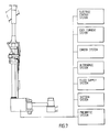
- Fig 7 shows the testing arrangement 14 in a position docked to a lead-through 4.
- Fig 7 is also explanatory shown peripheral systems associated to the testing arrangement.
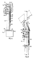
- Fig 8 shows the upper part of the testing arrangement docked to a cap lead-through 4 and with the pinching arm 78 and the sword guide 74 of the pinching arrangement 32 in a position suitable for insertion of the probe sword 85 into the sleeve gap.
- the central structure 24 of the testing arrangement 14 is positioned essentially coaxially below a lead-through 4, to which position the testing arrangement has been maneuvered by means of the manipulator 10.
- the testing arrangement 14 is maneuvered with precision by means of the manipulator 10 to the docked position shown in Fig 7, at which position the docking cone of the testing arrangement is connected, locked by virtue of geometry, to the sleeve funnel 9 of the cap lead-through.
- the sleeve 8, which thus is docked to the testing arrangement 14 is then slightly elevated in order to increase its lateral mobility. Thereafter, see Fig 8, the pinching arrangement 32 is elevated by means of the vertical beam driving unit 42 past the sleeve funnel 9.
- the upper part of the sword guide 74 is led by means of the sword guide actuating means 76 towards the sleeve so that a sleeve contracting surface 71 arranged at said upper part is in close contact with the sleeve 8.
- the pinching arrangement 32 is elevated further until the top of the sword guide contacts or is close to the lower end surface of the tube 6.
- the limit position is indicated by a limit switch, for example an inductive sensor, comprised in the top of the sword guide.
- the upper part of the pinching arm 78 is led towards the tube by means of the pinch-actuating means 80 so that a pinching surface 86 of the last mentioned upper part is in close contact with the outside surface of the tube 6.
- the sleeve 8 is now pressed out, by means of the pinching arm 78, the sword guide 74 and the actuating means 76,80, against the side of the tube 6, where the pinching arm is applied, in order to widen the sleeve gap before the insertion of the probe sword.
- a compliance that allows a deflection of the end of the sleeve and the end of the testing arrangement that are docked to each other, the deflection being of the magnitude of a few millimetres.
- the probe sword can now, via the sword guide 74, be inserted vertically into the widened sleeve gap by means of the sword driving unit 83 and be maneuvered by means of said driving unit over the height of the defined testing area.
- the central structure 24 is turned with the thereto non-rotatingly mounted pinching arrangement 32 by means of the rotation driving unit comprised in the frame 26.
- the movements are sequency-controlled and are controlled step by step by means of signals from limit switches arranged in said testing arrangement.
- Fig 9a shows an explanatory cross-section of a lead-through after the deflection of the sleeve 8 towards the inner wall of the tube 6.
- the pinching surface 86, the probe sword 85 and the top of the sword guide 74 are schematically shown in the figure. Pinching forces are drawn as arrows and are designated with an F.
- the central structure 24 with the pinching arrangement 32 rotates, the pinching surface 86 slides relative to the outer surface of the sleeve and the sleeve contacting surface 71 of the sword guide slides relative to the outside surface of the sleeve, while the engagement of the docking cone with the sleeve funnel is maintained.
- Fig 9b it is explanatory shown how the probe sword 85 in the inserted position acquires an essentially S-shaped bending due to the forced curvatures.
- peripheral support systems for control are associated with the testing arrangement.
- the following systems are, in the present example, connected to the testing arrangement: a control system for controlling the movements of the testing arrangement, an eddy current measurement system, a camera system for monitoring the movements of the testing arrangement, an ultrasonic system for determination of defects, a fluid-supplying system for supplying the sword with cleaning fluid and a contact medium, and a pneumatic system for actuating the pneumatic means comprised in the embodiment.
- the purpose of the inventive probe sword is, in accordance with the above description, to insert it in a gap between two concentric tubes and to displace it in the axial direction of the tubes as well as in a circular movement around an axis of symmetry.
- the probe sword is characterized in that it comprises a probe end, an elastic swordblade with a bent cross-section adapted to the shape of the gap, a connection means at the end opposite the probe end and a probe attached at the probe end, whereby the sword comprises at least one conduit, running along one edge of the sword, for conveyance of a fluid onto the probe end, and possibly at least one electric wire, running in the same way as the conduit, for the connection of the probe, and whereby the connection means serves for attachment at a sword-actuating means and for connection of an inlet conduit for fluid and of an elctric wire.
- Fig 10 is shown an explanatory sketch of an inventive probe sword 85 comprising a sword head 94, adapted for a recessed attachment of a probe 100, and a connection means 96.
- the probe sword 85 comprises at least one electric wire 97 and at least one fluid conduit 98, which are running in the sword blade along its edges from the connection means 96 to the sword head 94.
- the electric wire 97 is provided for possible power supply to and for transmitting measuring signals from the probe 100, while the fluid conduit 98 is provided for possible conveyance of fluid to said probe.
- the connection means 96 at the lower end of the sword comprises at least one electric connection 99 and at least one fluid conduit connection 101.
- the connection means 96 also comprises a means for fastening the sword at the lead-screw nut of the probe sword driving unit 83.
- Fig 11 shows, as an example, the upper part of a probe sword 85 together with cross-sections a, b, c, d and e from indicated parts of the sword.
- the sword head presents a through-aperture 102, which is provided for recessed mounting of a probe.
- the cross-sections a - e shows the curvature of the sword, whereby the curvature of the outer contour is adapted to the curvature of the inner surface of the outer tube 6, while the inner radius of the sword is determined by tensile property conditions.
- the essentially S-shaped curve, shown in Fig 9b, described by the sword in a position inserted into the gap puts high demands on the resiliency of the sword in two directions.
- the movement of the sword around the gap puts high demands on the stiffness of the sword in one of its transverse directions.
- parts of the sword are successively subject to flexural stress, where the cross-section of the sword takes an essentially plane shape and resumes its curved shape in the sleeve gap.
- the cross-section In order to stand up to the stress at the flexing of the sword, the cross-section is thin in the middle, while it has a thicker cross-section along the edges in order to attain a high moment of inertia against bending in the transverse direction of the sword and in order to contain said conduits and wires.
- Electric wires 97 and fluid conduits 98 are visible at the edges of the sword.
- Electrid wires and fluid conduits are, in the present embodiment recessed side by side at the two edges of the sword.
- the electric wires 97 protrudes out of the sword at the lower edge of the recess 102, and from there they can be connected to a probe arranged at the recess.
- the electric wires are realized in the form of coaxial cables.
- the fluid conduits are running in the sword head along the edges of the recess and debouches after a bend of 180° downwards at the upper edge of the recess. In this way, fluid can be fed to and be flushed over the attached probe.
- the material is important.
- the sword is realized in carbon fiber-reinforced plastic material.
- the sword is reinforced with Kevlar R and the plastic material may be an isoester.
- Figs 12a and 12b show, from the front and from the side, respectively, the upper part of an inventive probe sword 85 with a cleaning probe 104 for cleaning the sleeve gap attached at the sword head.
- the cleaning probe 104 is fastened to a resilient holder 106, which at one end in its turn is fastened to the sword.
- One or more brushes 108 are comprised in the cleaning probe. In the course of cleaning, the cleaning probe is led around in the sleeve gap, and cleaning fluid is fed via the fluid conduit 98 and is flushed over the brushes.
- Figs 13a and 13b show in the same way a probe sword 85 with an eddy current probe 110 for eddy current testing at the testing area in the sleeve gap.
- the eddy current probe 110 is likewise fastened to a resilient holder 106, which is fastened to the sword, and is (not shown) connected to the electric wire 97.
- Figs 14a and 14b show in the same way as the preceding Figs 12 - 13, a probe sword 85 with an ultrasonic probe 112 for ultrasonic testing at the testing area in the sleeve gap.
- the ultrasonic probe is, as the above mentioned probes, fastened to a resilient holder 106 and is (not shown) connected to the electric wire 97.
- a contact medium is needed. Water is preferably used as contact medium in the ultrasonic testing described in the present text. The contact medium is, during the testing, flushed over the ultrasonic probe via the fluid conduit 98.
- the fluid flushed out during the cleaning and the ultrasonic testing is, if it is a liquid, sucked in at the suction muzzle which is situated at the upper edge of the sword guide. Fluid or material moving along the side of the testing arrangement is collected in the collecting vessel situated at the frame.
Landscapes
- Physics & Mathematics (AREA)
- Engineering & Computer Science (AREA)
- Plasma & Fusion (AREA)
- General Engineering & Computer Science (AREA)
- High Energy & Nuclear Physics (AREA)
- Monitoring And Testing Of Nuclear Reactors (AREA)
- Investigating Or Analyzing Materials By The Use Of Magnetic Means (AREA)
- Investigating Strength Of Materials By Application Of Mechanical Stress (AREA)
- Investigating Or Analyzing Materials By The Use Of Ultrasonic Waves (AREA)
Abstract
Claims (13)
- Dispositif (14) de contrôle pour le contrôle de matériaux dans une traversée (4) d'un réacteur nucléaire, cette traversée (4) comprenant un premier tube (6) soudé dans une ouverture d'un couvercle (1) de réacteur et un second tube (8) inséré dans le premier tube (6), le premier tube (6) et le second tube (8) étant joints de manière étanche à une extrémité supérieure commune et le second tube (8) faisant saillie sous le couvercle (1) du réacteur par rapport au premier tube (6), ce dispositif de contrôle comprenant une épée (85) équipée d'une sonde disposée de manière à être insérée dans un interstice (20) annulaire qui se trouve entre les deux tubes et destinée à balayer une zone de contrôle qui s'étend autour de l'interstice, un manipulateur (10) étant disposé de manière à placer le dispositif de contrôle en position opposée à la traversée (4), caractérisé en ce que le dispositif (14) de contrôle comprend un dispositif (32) de pincement, qui applique une force de pincement entre un point de la surface extérieure du premier tube (6) et un point opposé de la surface extérieure d'une partie en saillie du second tube (8), afin d'élargir l'interstice (20) du côté du second tube (8) où la force de pincement est appliquée, un dispositif (74) de guidage d'épée coopérant avec le dispositif (32) de pincement pour guider l'épée (85) dans la partie élargie de l'interstice (20), un premier dispositif (24,40, 42,44) de soulèvement destiné à amener le dispositif de pincement au niveau de la partie inférieure du tube extérieur, un second dispositif (82,83,84) de levage destiné à insérer l'épée (85) dans l'interstice (20), et un dispositif de rotation destiné à déplacer, en coopération avec le dispositif (32) de pincement, la partie élargie de l'interstice le long de la périphérie intérieure du premier tube (6) et à déplacer en connexion avec celui-ci l'épée dans l'interstice en passant par la zone de contrôle, le dispositif (14) de contrôle pouvant être fixé au manipulateur mentionné précédemment, et le dispositif (14) de contrôle pouvant être amarré à un passage (4) choisi au moyen du manipulateur (10), les dispositifs de levage étant prévus sur le dispositif de rotation et le dispositif de pincement (32) étant prévu sur le premier dispositif de levage (24,40,42,44), et le dispositif (74) de guidage d'épée portant l'épée (85) étant prévu sur le second dispositif (82,83,84) de soulèvement, les deux dispositifs de soulèvement étant mobiles linéairement suivant la direction axiale des tubes.
- Dispositif de contrôle suivant la revendication 1, caractérisé en ce que le dispositif (74) de guidage d'épée peut se déplacer par pivotement entre une position qui permet le passage à l'épée (85) au-delà d'une pièce (9) d'extrémité disposée à l'extrémité inférieure du tube (8) intérieur et une position au-dessus de la partie (9) d'extrémité, à proximité ou contre la surface extérieure du tube (8) intérieur.
- Dispositif de contrôle suivant la revendication 1 ou 2, caractérisé en ce que le dispositif (74) de guidage d'épée est muni d'un capteur destiné à détecter, en connexion avec le mouvement de levée du premier dispositif de levage, le fait que le dispositif de guidage d'épée est en contact avec la partie inférieure du premier tube (6) ou est proche d'être en contact avec cette partie inférieure.
- Lame (85) sonde destinée à être insérée dans un interstice (20) annulaire entre deux tubes (6,8) disposés concentriquement et à être déplacée aussi bien suivant la direction axiale des tubes qu'autour de l'interstice (20) annulaire, caractérisée en ce que l'épée (85) sonde comprend une extrémité sonde, une lame d'épée élastique ayant une section transversale sensiblement en forme de U, des moyens (96) de connexion à l'extrémité opposée à l'extrémité de sonde et une sonde (100) montée à l'extrémité sonde, l'épée comprenant en outre au moins un conduit (98), s'étendant suivant un bord de l'épée, et destiné à acheminer un fluide à l'extrémité sonde, et facultativement au moins un fil (97) électrique, s'étendant suivant un bord de l'épée et destiné à la connexion à la sonde, et les moyens (96) de connexion comprenant des moyens de fixation à un actionneur (82,83,84) d'épée et de connexion de conduits d'entrée pour du fluide et de fil électrique d'entrée et/ou de fil électrique de sortie.
- Lame (85) sonde suivant la revendication 4, caractérisée en ce que la sonde (100) est fixée à un support (106) qui est fixé à l'extrémité sonde de l'épée, le support (106) étant élastique suivant une direction transversale.
- Lame (85) sonde suivant la revendication 4 ou 5, caractérisée en ce que l'épée est munie d'une ouverture de traversée dans laquelle la sonde (100) est montée.
- Lame (85) sonde suivant la revendication 4 ou 5, caractérisée en ce que la sonde (100) est une sonde (104) de nettoyage comprenant au moins une brosse (108), conçue pour nettoyer un interstice dans lequel l'épée est insérée en coopération avec un fluide qui est acheminé à l'extrémité de sonde par le conduit (98) mentionné.
- Lame (85) sonde suivant la revendication 4 ou 5, caractérisée en ce que la sonde (100) est une sonde pouvant être actionnée électriquement destinée au contrôle, comme par exemple une sonde (110) à courant de Foucault ou une sonde (112) à ultrasons.
- Lame (85) sonde suivant la revendication 4 ou 5, caractérisée en ce que la lame d'épée a, sur une partie de sa longueur, une section transversale légèrement en forme de U avec des jambes épaissies et un fond mince, afin de donner un grand moment d'inertie par rapport au plan longitudinal de symétrie de la lame d'épée en raison des jambes épaissies ainsi que pour ménager de la place pour le conduit (98) et le fil (97) et pour donner, en raison du fond mince, une aptitude à se courber élastiquement par rapport à un centre de courbure qui se trouve sur le côté convexe de la section transversale en forme de U.
- Procédé pour contrôler des matériaux dans une traversée (4) d'un réacteur nucléaire, cette traversée (4) comprenant un premier tube (6) soudé dans une ouverture d'un couvercle (1) de réacteur et un second tube (8) inséré dans le premier tube (6), le premier tube (6) et le second tube (8) étant joints de manière étanche à une extrémité supérieure commune, le second tube (8) faisant saillie au-delà du premier tube (6) sous le couvercle (1) de réacteur et un interstice (20) annulaire se trouvant entre les deux tubes, caractérisé en ce qu'il comprend les étapes qui consistent à amarrer un dispositif (14) de contrôle à l'extrémité inférieure du second tube (8),à lever le second tube (8) amarré et le dispositif (14) de contrôle de manière. à augmenter la capacité de déplacement latéral du second tube (8);à élargir l'interstice (20) d'un côté des tubes (6, 8) en appliquant une force de pincement entre un point de la surface extérieure du premier tube (6) et un point opposé de la surface extérieure d'une partie en saillie du second tube (8);à insérer une sonde dans la partie élargie de l'interstice (20), età balayer une zone de contrôle sélectionnée dans l'interstice (20) au moyen de la sonde.
- Procédé suivant la revendication 10, caractérisé par les étapes supplémentaires qui consistent à déplacer la partie élargie de l'interstice (20) en déplaçant au moins l'un des points d'application de la force de pincement et à déplacer la sonde ayant la partie élargie de l'interstice (20) autour de l'axe de symétrie principal de la traversée.
- Procédé suivant la revendication 10 ou 11, caractérisé en ce que la sonde est appliquée à une épée (85) qui est souple suivant une première direction transversale et est rigide suivant une seconde direction transversale perpendiculaire à la première direction transversale.
- Procédé suivant la revendication 10 ou 11, caractérisé par le fait qu'elle comprend l'étape supplémentaire qui consiste à insérer l'épée (85) équipée d'une sonde dans la partie élargie de l'interstice (20) au-delà d'une pièce (9) d'extrémité disposée sur le second tube (8), la souplesse de l'épée lui permettant de s'adapter à la géométrie du premier tube (6) et du second tube (8).
Applications Claiming Priority (3)
| Application Number | Priority Date | Filing Date | Title |
|---|---|---|---|
| SE9302087A SE505475C2 (sv) | 1993-06-16 | 1993-06-16 | Provningsanordning, sondsvärd och förfarande för materialprovning av en genomföring vid en kärnreaktor |
| SE9302087 | 1993-06-16 | ||
| PCT/SE1994/000416 WO1994029878A1 (fr) | 1993-06-16 | 1994-05-05 | Dispositif d'essai materiaux, monte notamment dans un reacteur a eau sous pression |
Publications (2)
| Publication Number | Publication Date |
|---|---|
| EP0649559A1 EP0649559A1 (fr) | 1995-04-26 |
| EP0649559B1 true EP0649559B1 (fr) | 1996-07-24 |
Family
ID=20390312
Family Applications (1)
| Application Number | Title | Priority Date | Filing Date |
|---|---|---|---|
| EP94919030A Expired - Lifetime EP0649559B1 (fr) | 1993-06-16 | 1994-05-05 | Dispositif d'essai de materiaux, monte notamment dans un reacteur a eau sous pression |
Country Status (7)
| Country | Link |
|---|---|
| US (1) | US5596612A (fr) |
| EP (1) | EP0649559B1 (fr) |
| KR (1) | KR960703264A (fr) |
| DE (1) | DE69400335T2 (fr) |
| ES (1) | ES2091144T3 (fr) |
| SE (1) | SE505475C2 (fr) |
| WO (1) | WO1994029878A1 (fr) |
Families Citing this family (6)
| Publication number | Priority date | Publication date | Assignee | Title |
|---|---|---|---|---|
| DE19511863C2 (de) * | 1995-03-31 | 1998-08-20 | Daimler Benz Ag | Automatgetriebesteuerung mit betriebsweisenadaptivem Schaltverhalten |
| FR2755239B1 (fr) * | 1996-10-30 | 1999-01-15 | Framatome Sa | Procede et dispositif d'examen optique d'un element dispose a l'interieur d'un mecanisme de deplacement d'une barre de commande d'un reacteur nucleaire refroidi par de l'eau sous pression |
| JP3864180B2 (ja) * | 2004-11-15 | 2006-12-27 | 独立行政法人 宇宙航空研究開発機構 | 超音波試験方法及びこれに用いる超音波試験装置 |
| KR100680482B1 (ko) | 2005-12-28 | 2007-02-08 | 두산중공업 주식회사 | 원자력발전소의 원자로헤드 노즐 검사장치 |
| KR100834686B1 (ko) | 2006-07-28 | 2008-06-02 | 두산중공업 주식회사 | 원자로 헤드 관통관 보수 로봇용 원격 제어 가이드 시스템 |
| KR101494455B1 (ko) * | 2013-01-31 | 2015-02-17 | 한전케이피에스 주식회사 | 원자로 헤드 관통관 검사 장치 |
Family Cites Families (15)
| Publication number | Priority date | Publication date | Assignee | Title |
|---|---|---|---|---|
| US4116766A (en) * | 1976-08-31 | 1978-09-26 | The United States Of America As Represented By The Department Of Energy | Ultrasonic dip seal maintenance system |
| JPS5518962A (en) * | 1978-07-27 | 1980-02-09 | Hitachi Ltd | Device for detecting in nuclear reactor vessel |
| US4368644A (en) * | 1981-05-26 | 1983-01-18 | Combustion Engineering, Inc. | Tool for inspecting defects in irregular weld bodies |
| US4452753A (en) * | 1982-02-26 | 1984-06-05 | Combustion Engineering, Inc. | Apparatus for cleaning and inspecting closure studs of a nuclear reactor vessel |
| US4548785A (en) * | 1982-12-14 | 1985-10-22 | General Electric Company | Stub tube inspection device |
| DE3329483A1 (de) * | 1983-08-16 | 1985-03-07 | Kraftwerk Union AG, 4330 Mülheim | Aussen an einem rohr ansetzbarer pruefmanipulator |
| DE3438971A1 (de) * | 1984-04-03 | 1985-10-10 | Kraftwerk Union AG, 4330 Mülheim | Spezial-endoskop zur optischen risspruefung |
| US4957694A (en) * | 1988-11-30 | 1990-09-18 | Westinghouse Electric Corp. | Removal of obstructions in thimbles of nuclear power reactors |
| US4883124A (en) * | 1988-12-08 | 1989-11-28 | Mobil Oil Corporation | Method of enhancing hydrocarbon production in a horizontal wellbore in a carbonate formation |
| US5118464A (en) * | 1991-03-15 | 1992-06-02 | General Electric Company | Method of ultrasonic inspection of materials through opaque barriers |
| FR2688091B1 (fr) * | 1992-02-28 | 1994-05-27 | Framatome Sa | Procede de controle et de reparation de la surface interne d'une piece tubulaire de traversee du couvercle de la cuve d'un reacteur nucleaire et dispositif pour la mise en óoeuvre de ce procede. |
| US5272734A (en) * | 1992-04-09 | 1993-12-21 | General Electric Company | Repair of incore housings using ultrasonic examinations |
| DE4215700C2 (de) * | 1992-05-13 | 1994-03-10 | Bbc Reaktor Gmbh | Verfahren und Einrichtung zum zerstörungsfreien Prüfen einer Durchführung eines Reaktordruckbehälter-Deckels |
| US5323429A (en) * | 1993-01-15 | 1994-06-21 | Westinghouse Electric Corporation | Electrochemical monitoring of vessel penetrations |
| US5377237A (en) * | 1993-04-05 | 1994-12-27 | General Electric Company | Method of inspecting repaired stub tubes in boiling water nuclear reactors |
-
1993
- 1993-06-16 SE SE9302087A patent/SE505475C2/sv not_active IP Right Cessation
-
1994
- 1994-05-05 DE DE69400335T patent/DE69400335T2/de not_active Expired - Fee Related
- 1994-05-05 KR KR1019950705743A patent/KR960703264A/ko not_active Abandoned
- 1994-05-05 WO PCT/SE1994/000416 patent/WO1994029878A1/fr not_active Ceased
- 1994-05-05 ES ES94919030T patent/ES2091144T3/es not_active Expired - Lifetime
- 1994-05-05 EP EP94919030A patent/EP0649559B1/fr not_active Expired - Lifetime
- 1994-05-05 US US08/238,496 patent/US5596612A/en not_active Expired - Fee Related
Also Published As
| Publication number | Publication date |
|---|---|
| SE505475C2 (sv) | 1997-09-01 |
| SE9302087L (sv) | 1994-12-17 |
| SE9302087D0 (sv) | 1993-06-16 |
| DE69400335D1 (de) | 1996-08-29 |
| US5596612A (en) | 1997-01-21 |
| KR960703264A (ko) | 1996-06-19 |
| EP0649559A1 (fr) | 1995-04-26 |
| WO1994029878A1 (fr) | 1994-12-22 |
| DE69400335T2 (de) | 1997-01-23 |
| ES2091144T3 (es) | 1996-10-16 |
Similar Documents
| Publication | Publication Date | Title |
|---|---|---|
| US6076407A (en) | Pipe inspection probe | |
| US7092477B2 (en) | BWR inspection manipulator | |
| US5586155A (en) | Narrow access scanning positioner for inspecting core shroud in boiling water reactor | |
| US6044769A (en) | In-pipe work apparatus | |
| US5028381A (en) | Device for the ultrasonic non-destructive testing of a circular weld inside a steam generator tube | |
| EP0465106B1 (fr) | Système et méthode pour souder à laser la surface intérieure d'une conduite | |
| US4368644A (en) | Tool for inspecting defects in irregular weld bodies | |
| JPH0134342B2 (fr) | ||
| US6526114B2 (en) | Remote automated nuclear reactor jet pump diffuser inspection tool | |
| US5596612A (en) | Testing arrangement for materials testing, particularly in a pressurized-water reactor | |
| EP2907139B1 (fr) | Appareil et procédé de commande de position de capteur dans des zones à accès limité à l'intérieur d'un réacteur nucléaire | |
| JPH0338149B2 (fr) | ||
| EP0580311B1 (fr) | Appareil de détection de défauts | |
| CN102507610A (zh) | 管体周向焊缝自动化射线检查臂 | |
| US9318226B2 (en) | Apparatus and method to inspect, modify, or repair nuclear reactor core shrouds | |
| JP3710539B2 (ja) | 遠隔炉内作業装置およびその作業方法 | |
| JP4000032B2 (ja) | 炉底部作業装置および作業方法 | |
| JP2007003400A (ja) | 制御棒貫通孔部材検査装置 | |
| JP7086825B2 (ja) | ライザブレースの検査装置及び検査方法 | |
| US4463609A (en) | Method and apparatus for testing the soundness of the welds of off-shore structures during service | |
| EP2907140B1 (fr) | Appareil et procédé permettant d'inspecter, de modifier ou de réparer des enveloppes de coeur de réacteur nucléaire | |
| JPH1123785A (ja) | 原子炉内配管ノズル作業装置 | |
| JP7489542B2 (ja) | 使用済燃料プールのライニングを修理するための設備及びシステム | |
| JPH1039084A (ja) | 超音波探傷装置 | |
| JP3553080B2 (ja) | 炉心容器の外壁をそれを包囲する熱遮蔽体の範囲で点検するための装置および方法 |
Legal Events
| Date | Code | Title | Description |
|---|---|---|---|
| PUAI | Public reference made under article 153(3) epc to a published international application that has entered the european phase |
Free format text: ORIGINAL CODE: 0009012 |
|
| 17P | Request for examination filed |
Effective date: 19941217 |
|
| AK | Designated contracting states |
Kind code of ref document: A1 Designated state(s): BE CH DE ES FR GB LI SE |
|
| 17Q | First examination report despatched |
Effective date: 19950718 |
|
| GRAH | Despatch of communication of intention to grant a patent |
Free format text: ORIGINAL CODE: EPIDOS IGRA |
|
| GRAA | (expected) grant |
Free format text: ORIGINAL CODE: 0009210 |
|
| AK | Designated contracting states |
Kind code of ref document: B1 Designated state(s): BE CH DE ES FR GB LI SE |
|
| REF | Corresponds to: |
Ref document number: 69400335 Country of ref document: DE Date of ref document: 19960829 |
|
| REG | Reference to a national code |
Ref country code: CH Ref legal event code: NV Representative=s name: BOVARD AG PATENTANWAELTE |
|
| ET | Fr: translation filed | ||
| REG | Reference to a national code |
Ref country code: ES Ref legal event code: FG2A Ref document number: 2091144 Country of ref document: ES Kind code of ref document: T3 |
|
| REG | Reference to a national code |
Ref country code: ES Ref legal event code: FG2A Ref document number: 2091144 Country of ref document: ES Kind code of ref document: T3 |
|
| PLBI | Opposition filed |
Free format text: ORIGINAL CODE: 0009260 |
|
| PLBF | Reply of patent proprietor to notice(s) of opposition |
Free format text: ORIGINAL CODE: EPIDOS OBSO |
|
| 26 | Opposition filed |
Opponent name: SIEMENS AG Effective date: 19970423 |
|
| PLBF | Reply of patent proprietor to notice(s) of opposition |
Free format text: ORIGINAL CODE: EPIDOS OBSO |
|
| PLBF | Reply of patent proprietor to notice(s) of opposition |
Free format text: ORIGINAL CODE: EPIDOS OBSO |
|
| PLBO | Opposition rejected |
Free format text: ORIGINAL CODE: EPIDOS REJO |
|
| PLBN | Opposition rejected |
Free format text: ORIGINAL CODE: 0009273 |
|
| STAA | Information on the status of an ep patent application or granted ep patent |
Free format text: STATUS: OPPOSITION REJECTED |
|
| 27O | Opposition rejected |
Effective date: 19981001 |
|
| PGFP | Annual fee paid to national office [announced via postgrant information from national office to epo] |
Ref country code: DE Payment date: 20000502 Year of fee payment: 7 |
|
| PGFP | Annual fee paid to national office [announced via postgrant information from national office to epo] |
Ref country code: GB Payment date: 20000503 Year of fee payment: 7 |
|
| PGFP | Annual fee paid to national office [announced via postgrant information from national office to epo] |
Ref country code: SE Payment date: 20000504 Year of fee payment: 7 |
|
| PGFP | Annual fee paid to national office [announced via postgrant information from national office to epo] |
Ref country code: FR Payment date: 20000510 Year of fee payment: 7 |
|
| PGFP | Annual fee paid to national office [announced via postgrant information from national office to epo] |
Ref country code: CH Payment date: 20000512 Year of fee payment: 7 |
|
| PGFP | Annual fee paid to national office [announced via postgrant information from national office to epo] |
Ref country code: ES Payment date: 20000531 Year of fee payment: 7 |
|
| PGFP | Annual fee paid to national office [announced via postgrant information from national office to epo] |
Ref country code: BE Payment date: 20000717 Year of fee payment: 7 |
|
| PG25 | Lapsed in a contracting state [announced via postgrant information from national office to epo] |
Ref country code: GB Free format text: LAPSE BECAUSE OF NON-PAYMENT OF DUE FEES Effective date: 20010505 |
|
| PG25 | Lapsed in a contracting state [announced via postgrant information from national office to epo] |
Ref country code: SE Free format text: LAPSE BECAUSE OF NON-PAYMENT OF DUE FEES Effective date: 20010506 |
|
| PG25 | Lapsed in a contracting state [announced via postgrant information from national office to epo] |
Ref country code: ES Free format text: LAPSE BECAUSE OF NON-PAYMENT OF DUE FEES Effective date: 20010507 |
|
| PG25 | Lapsed in a contracting state [announced via postgrant information from national office to epo] |
Ref country code: BE Free format text: LAPSE BECAUSE OF NON-PAYMENT OF DUE FEES Effective date: 20010531 |
|
| PG25 | Lapsed in a contracting state [announced via postgrant information from national office to epo] |
Ref country code: LI Free format text: LAPSE BECAUSE OF NON-PAYMENT OF DUE FEES Effective date: 20010604 Ref country code: CH Free format text: LAPSE BECAUSE OF NON-PAYMENT OF DUE FEES Effective date: 20010604 |
|
| BERE | Be: lapsed |
Owner name: ABB TEKNISKA RONTGENCENTRALEN A.B. Effective date: 20010531 |
|
| GBPC | Gb: european patent ceased through non-payment of renewal fee |
Effective date: 20010505 |
|
| REG | Reference to a national code |
Ref country code: CH Ref legal event code: PL |
|
| PG25 | Lapsed in a contracting state [announced via postgrant information from national office to epo] |
Ref country code: FR Free format text: LAPSE BECAUSE OF NON-PAYMENT OF DUE FEES Effective date: 20020131 |
|
| PG25 | Lapsed in a contracting state [announced via postgrant information from national office to epo] |
Ref country code: DE Free format text: LAPSE BECAUSE OF NON-PAYMENT OF DUE FEES Effective date: 20020301 |
|
| REG | Reference to a national code |
Ref country code: ES Ref legal event code: FD2A Effective date: 20030303 |