EP0649731A2 - Verstärkte Struktur aus Kunststoff - Google Patents
Verstärkte Struktur aus Kunststoff Download PDFInfo
- Publication number
- EP0649731A2 EP0649731A2 EP94116489A EP94116489A EP0649731A2 EP 0649731 A2 EP0649731 A2 EP 0649731A2 EP 94116489 A EP94116489 A EP 94116489A EP 94116489 A EP94116489 A EP 94116489A EP 0649731 A2 EP0649731 A2 EP 0649731A2
- Authority
- EP
- European Patent Office
- Prior art keywords
- rib
- plate
- plastic
- reinforced structure
- made reinforced
- Prior art date
- Legal status (The legal status is an assumption and is not a legal conclusion. Google has not performed a legal analysis and makes no representation as to the accuracy of the status listed.)
- Granted
Links
Images

Classifications
-
- B—PERFORMING OPERATIONS; TRANSPORTING
- B29—WORKING OF PLASTICS; WORKING OF SUBSTANCES IN A PLASTIC STATE IN GENERAL
- B29D—PRODUCING PARTICULAR ARTICLES FROM PLASTICS OR FROM SUBSTANCES IN A PLASTIC STATE
- B29D99/00—Subject matter not provided for in other groups of this subclass
- B29D99/001—Producing wall or panel-like structures, e.g. for hulls, fuselages, or buildings
- B29D99/0014—Producing wall or panel-like structures, e.g. for hulls, fuselages, or buildings provided with ridges or ribs, e.g. joined ribs
-
- E—FIXED CONSTRUCTIONS
- E04—BUILDING
- E04C—STRUCTURAL ELEMENTS; BUILDING MATERIALS
- E04C2/00—Building elements of relatively thin form for the construction of parts of buildings, e.g. sheet materials, slabs, or panels
- E04C2/02—Building elements of relatively thin form for the construction of parts of buildings, e.g. sheet materials, slabs, or panels characterised by specified materials
- E04C2/10—Building elements of relatively thin form for the construction of parts of buildings, e.g. sheet materials, slabs, or panels characterised by specified materials of wood, fibres, chips, vegetable stems, or the like; of plastics; of foamed products
- E04C2/20—Building elements of relatively thin form for the construction of parts of buildings, e.g. sheet materials, slabs, or panels characterised by specified materials of wood, fibres, chips, vegetable stems, or the like; of plastics; of foamed products of plastics
-
- E—FIXED CONSTRUCTIONS
- E04—BUILDING
- E04C—STRUCTURAL ELEMENTS; BUILDING MATERIALS
- E04C2/00—Building elements of relatively thin form for the construction of parts of buildings, e.g. sheet materials, slabs, or panels
- E04C2/30—Building elements of relatively thin form for the construction of parts of buildings, e.g. sheet materials, slabs, or panels characterised by the shape or structure
-
- B—PERFORMING OPERATIONS; TRANSPORTING
- B29—WORKING OF PLASTICS; WORKING OF SUBSTANCES IN A PLASTIC STATE IN GENERAL
- B29C—SHAPING OR JOINING OF PLASTICS; SHAPING OF MATERIAL IN A PLASTIC STATE, NOT OTHERWISE PROVIDED FOR; AFTER-TREATMENT OF THE SHAPED PRODUCTS, e.g. REPAIRING
- B29C70/00—Shaping composites, i.e. plastics material comprising reinforcements, fillers or preformed parts, e.g. inserts
- B29C70/04—Shaping composites, i.e. plastics material comprising reinforcements, fillers or preformed parts, e.g. inserts comprising reinforcements only, e.g. self-reinforcing plastics
- B29C70/28—Shaping operations therefor
- B29C70/40—Shaping or impregnating by compression not applied
- B29C70/42—Shaping or impregnating by compression not applied for producing articles of definite length, i.e. discrete articles
- B29C70/46—Shaping or impregnating by compression not applied for producing articles of definite length, i.e. discrete articles using matched moulds, e.g. for deforming sheet moulding compounds [SMC] or prepregs
-
- B—PERFORMING OPERATIONS; TRANSPORTING
- B29—WORKING OF PLASTICS; WORKING OF SUBSTANCES IN A PLASTIC STATE IN GENERAL
- B29K—INDEXING SCHEME ASSOCIATED WITH SUBCLASSES B29B, B29C OR B29D, RELATING TO MOULDING MATERIALS OR TO MATERIALS FOR MOULDS, REINFORCEMENTS, FILLERS OR PREFORMED PARTS, e.g. INSERTS
- B29K2101/00—Use of unspecified macromolecular compounds as moulding material
- B29K2101/12—Thermoplastic materials
Definitions
- the present invention relates to a plastic-made reinforced structure which is lightweight and yet has excellent strength.
- Plastic plates have been in wide use as a structural material for various applications, owing to their light weight and excellent physical properties. They, however, are inferior in static or impact strength when used in the form of a flat plate; in order to reinforce the strength, rib(s) are often bonded to the surface of the plate.
- rib(s)-bonded plate there are known reinforced structures comprising (a) a plate and (b) continuous or independent rectangular box-shaped or honeycomb-shaped ribs bonded to the plate surface.
- a plastic-made reinforced structure comprising a thermoplastic resin-made plate and cylindrical rib(s) made of the same resin as that of said plate, connected to at least one side of said plate perpendicularly to the side so that the plate and the rib(s) form one piece, in which structure the following relationships hold: d1 ⁇ 20 mm, 1 > d1/d2 ⁇ 0.7, H ⁇ 30 mm, and 1 ⁇ d1/H ⁇ 0.3 wherein d1 and d2 are the inside and outside diameters of each rib at the root of the rib, i.e. the joint of the rib to the plate; and H is the length of each rib from the root to the front end.
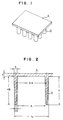
- Fig. 1 shows a plastic-made reinforced structure having cylindrical ribs, according to the present invention.
- A is a top plate and B is individual cylindrical ribs.
- Fig. 2 shows the sectional view of each rib of the structure of Fig. 1.
- each number indicates a length (mm);
- d1 and d2 are the inside and outside diameters of each rib at the root of each rib, i.e. the joint of the rib to the plate;
- H is the length of each rib from the root to the front end.
- Fig. 3 shows a plastic-made reinforced structure having box-shaped ribs.
- A is a top plate and B is individual box-shaped ribs.
- the base material is a thermoplastic resin.
- the thermoplastic resin is exemplified by polyethylene, polypropylene, polyvinyl chloride, nylon, polycarbonate, polyethylene terephthalate, PMMA, ABS resin, modified resins thereof, polymer alloys, mixtures between one of said resins and a rubber component (e.g. thermoplastic elastomer typified by EPDM), and mixtures thereof.
- a rubber component e.g. thermoplastic elastomer typified by EPDM
- polyolefin resins such as homopolymers of ethylene, propylene, etc. or copolymers of said monomer and other copolymerizable component, and particularly preferable is a polypropylene resin.
- thermoplastic resin as the base material may be mixed with a fiber (e.g. glass fiber, carbon fiber or polyamide fiber) and a filler (e.g. talc) as necessary.
- a fiber e.g. glass fiber, carbon fiber or polyamide fiber
- a filler e.g. talc
- various additives ordinarily used such as an antioxidant, ultra-violet absorber, flame retardant and coloring agent.
- the plastic-made reinforced structure of the present invention uses the above-mentioned thermoplastic resin as the base material, and comprises a thermoplastic resin-made plate and cylindrical rib(s) connected to at least one side of the plate perpendicularly to the plate surface so that the plate and the rib(s) form one piece. It is requisite that the thermoplastic resin-made plate which is the base of the structure (said plate is hereinafter referred to simply as base plate, in some cases) and the cylindrical rib(s) for reinforcement are both made of the same material and that the base plate and the cylindrical rib(s) are connected so as to form one piece.
- the plastic-made reinforced structure of the present invention is produced by a method which comprises forming a base plate and rib(s) simultaneously in one piece, for example, a press-molding method which comprises feeding a molten thermo-plastic resin into between male and female dies each designed in a given shape and then clamping the dies or conducting feeding and clamping simultaneously, and an injection-molding method which comprises injecting a molten resin into a die.
- a press-molding method which comprises feeding a molten thermo-plastic resin into between male and female dies each designed in a given shape and then clamping the dies or conducting feeding and clamping simultaneously
- an injection-molding method which comprises injecting a molten resin into a die.
- Any structure produced by bonding a base plate and rib(s) separately prepared, by fusion or with an adhesive is inferior in mechanical strengths and is not included in the plastic-made reinforced structure of the present invention.
- the shape of the base plate can be selected freely so as to best meet the application purpose of the structure.
- the base plate may have a flat surface or a curved surface and its shape is determined entirely depending upon the application purpose of the structure.
- the cylindrical rib(s) is (are) generally connected to one side of the base plate but, depending upon the application purpose of the structure or as any necessity arises, may be connected partially to both sides of the base plate.
- the cylindrical rib(s) is (are) connected to the base plate so that the lengthwise direction of rib(s) are perpendicular to the surface of the base plate.
- perpendicular to the surface of the base plate means the followings. That is, when the surface of the base plate is a flat surface, said expression means that the lengthwise direction of each rib intersects the flat surface at right angles; and when the surface of the base plate is a curved surface, said expression means that the lengthwise direction of each rib is normal to the curved surface, or intersects the tangent of the curved surface with which each rib contacts, at right angles.
- the rib(s) bonded to the base plate has (have) a cylindrical shape.
- cylindrical rib refers to a hollow rib whose cross-section intersecting the lengthwise direction of rib at right angles has a double-circle shape. These circles are preferably true circles but may slightly deviate therefrom to, for example, an oval as long as the strength of the structure is not greatly impaired.
- the relationships between the size and thickness of each rib is very important. That is, the following relationships must hold: d1 ⁇ 20 mm, 1 > d1/d2 ⁇ 0.7, H ⁇ 30 mm, and 1 ⁇ d1/H ⁇ 0.3 wherein d1 and d2 are the inside and outside diameters of each rib at the root of the rib, i.e. the joint of the rib to the plate; and H is the length of each rib from the root to the front end.
- d1 smaller than 20 mm is not preferable because the resulting strength is small.
- the upper limit of d1 is not particularly restricted. d1 may vary depending upon the size of base plate, etc. d1, even when too large, gives a low reinforcement effect in some cases; therefore, the upper limit of d1 is generally about 80 mm, preferably about 60 mm.
- the thickness of each rib is larger than necessary as compared with the size of each rib, which results in increased weight of structure and fails to achieve a light weight.
- the ratio d1/d2 approaches 1, the thickness of each rib becomes smaller. Too small a rib thickness, however, gives a low reinforcing effect; therefore, the ratio d1/d2 is preferably 0.98 or smaller.
- each rib may be the same at the root and at the front end, or may be smaller at the front end. The latter is preferable because of the productional advantage and the milder impact absorption.
- the thickness of the rib decreases continuously from the root to the front end.
- the present plastic-made reinforced structure shows an excellent reinforcing effect when it is a comparative large structure, i.e., H is 30 mm or more. Further, in the relationships between H and d1 (the inside diameter of each rib), 1 ⁇ d1/H ⁇ 0.3 gives an excellent reinforcing effect.
- the ratio d1/H is preferably 1 ⁇ d1/H ⁇ 0.4, and more preferably 1 ⁇ d1/H ⁇ 0.5.
- the number of ribs is at least one and generally two or more depending upon the size of the base plate.
- the number of ribs, the distance between ribs and the position of each rib are determined appropriately depending upon the size and shape of the base plate and the design strength of the reinforced structure to be produced.
- each rib is determined appropriately based on the respective design values which vary depending upon the application purpose of the reinforced structure, and accordingly are not particularly restricted.
- Any auxiliary ribs connecting the cylindrical ribs may be provided as necessary, whereby a further reinforcing effect can be obtained.
- the plastic-made reinforced structure of the present invention as compared with conventional structures having rectangular box-shaped rib(s), can exhibit higher mechanical strengths at the same resin amount and can be used as a structure of light weight and yet excellent strength.
- a polypropylene resin (Sumitomo Noblen AH 561, a product of SUMITOMO CHEMICAL CO., LTD.) of molten state was fed into the two dies of a press molding machine comprising male and female dies, while the two dies were in an open state. Then, clamping and cooling were applied in this order, whereby was obtained a plastic-made reinforced structure as shown in Fig. 1, which comprised a rectangular top plate of 300 mm x 400 mm x 4 mm (thickness) and 12 cylindrical ribs having a double-circle cross-sectional shape, connected perpendicularly to the plate, the ribs being arranged at equal intervals in three rows each consisting of four ribs. The cross section of each rib of the structure is shown in Fig. 2.
- the rib thickness at the root was 3 mm; the rib thickness at the front end was 0.5 mm; the rib diameter between the rib thickness centers was 31.8 mm; the rib height (H) was 48 mm; the ratio (d1/d2) of the rib inside diameter and the rib outside diameter was 0.83; and the ratio (d1/H) of the rib inside diameter and the rib height was 0.6.
- the resin amount of the structure was such that the resin amount of the top plate was 367 g, the resin amount of each one rib was 71.8 g and the total resin amount was 1,228.6 g.
- the structure was placed on a flat iron plate so that the front end of each rib contacted with the iron plate.
- a pressure was applied uniformly to the whole area of the top plate of the structure from above the top plate towards the ribs at a rate of 100 mm per minute, to measure the primary buckling strength of the structure.
- the yield load of the structure was 1,310 kgf.
- a plastic-made reinforced structure as shown in Fig. 3, which comprised a rectangular top plate of 300 mm x 400 mm x 4 mm (thickness) and 12 box-shaped ribs having a square cross section, connected perpendicularly to the plate, the ribs being arranged at equal intervals in three rows each consisting of four ribs.
- the rib thickness at the root was 3 mm; the rib thickness at the front end was 0.5 mm; the distance between the rib thickness centers was 25 mm; and the rib height was 48 mm.
- the resin amount of the structure was such that the resin amount of the top plate was 368 g, the resin amount of each one rib was 72.5 g and the total resin amount was 1,238 g.
- the structure was measured for primary buckling strength in the same manner as in Example 1.
- the yield load of the structure was 950 kgf.
- the plastic-made reinforced structure of the present invention remarkably shows an excellent yield load and gives an excellent effect for a plastic-made reinforced structure.
Landscapes
- Engineering & Computer Science (AREA)
- Architecture (AREA)
- Civil Engineering (AREA)
- Structural Engineering (AREA)
- Mechanical Engineering (AREA)
- Life Sciences & Earth Sciences (AREA)
- Wood Science & Technology (AREA)
- Casting Or Compression Moulding Of Plastics Or The Like (AREA)
- Laminated Bodies (AREA)
Applications Claiming Priority (3)
| Application Number | Priority Date | Filing Date | Title |
|---|---|---|---|
| JP26350593 | 1993-10-21 | ||
| JP26350593 | 1993-10-21 | ||
| JP263505/93 | 1993-10-21 |
Publications (3)
| Publication Number | Publication Date |
|---|---|
| EP0649731A2 true EP0649731A2 (de) | 1995-04-26 |
| EP0649731A3 EP0649731A3 (de) | 1996-08-14 |
| EP0649731B1 EP0649731B1 (de) | 2000-04-26 |
Family
ID=17390465
Family Applications (1)
| Application Number | Title | Priority Date | Filing Date |
|---|---|---|---|
| EP94116489A Expired - Lifetime EP0649731B1 (de) | 1993-10-21 | 1994-10-19 | Verstärkte Struktur aus Kunststoff |
Country Status (2)
| Country | Link |
|---|---|
| EP (1) | EP0649731B1 (de) |
| DE (1) | DE69424117T2 (de) |
Family Cites Families (5)
| Publication number | Priority date | Publication date | Assignee | Title |
|---|---|---|---|---|
| FR2325503A1 (fr) * | 1975-09-29 | 1977-04-22 | Planet Wattohm Sa | Sandwich a ame alveolee en resine |
| DE3412846A1 (de) * | 1984-04-05 | 1985-10-17 | Hoechst Ag, 6230 Frankfurt | Flaechenfoermiger sandwichformkoerper |
| US4601936A (en) * | 1985-04-01 | 1986-07-22 | General Motors Corporation | Glass fiber mat reinforced plastic panels without the fiber readout defect |
| EP0512431B1 (de) * | 1991-05-04 | 1996-12-18 | Hoechst Aktiengesellschaft | Verfahren zur Herstellung eines dreidimensional verformten Textilmaterials und seine Verwendung |
| US5234740A (en) * | 1991-08-28 | 1993-08-10 | Minnesota Mining And Manufacturing Company | Slip control sheeting and articles covered with same |
-
1994
- 1994-10-19 DE DE69424117T patent/DE69424117T2/de not_active Expired - Fee Related
- 1994-10-19 EP EP94116489A patent/EP0649731B1/de not_active Expired - Lifetime
Also Published As
| Publication number | Publication date |
|---|---|
| DE69424117D1 (de) | 2000-05-31 |
| EP0649731A3 (de) | 1996-08-14 |
| EP0649731B1 (de) | 2000-04-26 |
| DE69424117T2 (de) | 2000-12-21 |
Similar Documents
| Publication | Publication Date | Title |
|---|---|---|
| US5131778A (en) | Coupling structure and method of resin moldings | |
| EP4061605B1 (de) | Randgestaltung einer flächigen versteifungsstruktur für ein bauteil | |
| EP0623434A1 (de) | Durchsichtige Form für Beton | |
| HU9402251D0 (en) | Termoplastic polymer form-bodies and process for producing them, and the use them | |
| US5618607A (en) | Plastic-made reinforced structure | |
| BR9007394A (pt) | Ligas dinamicamente vulcanizadas com dois copolimeros na fase reticulada e uma matriz cristalina | |
| CA2013209A1 (en) | Method for reducing hollow glass sphere fracture in thermoplastic resin by in situ polymerization/extrusion | |
| CA2013210A1 (en) | Moldable low density thermoplastic composite with hollow glass spheres and the method for compounding | |
| EP0649731B1 (de) | Verstärkte Struktur aus Kunststoff | |
| US6343895B1 (en) | Resin net and its production method | |
| DE3134715A1 (de) | Biegefestes bauteil, insbesondere stossstange fuer fahrzeuge | |
| EP0084629B1 (de) | Stossleiste für Kraftfahrzeugkarosserien | |
| US20060046039A1 (en) | Composite component | |
| EP0608435B1 (de) | Armaturenbrett | |
| JPS6325019A (ja) | 板状製品の製造方法 | |
| DE102018214176B4 (de) | Untere Aussteifung für eine Stossstange eines Fahrzeugs | |
| CN217682606U (zh) | 一种汽车塑料卡扣 | |
| JPH07164566A (ja) | プラスチック製強化構造体 | |
| EP0623435A1 (de) | Verfahren zur Herstellung einer Form für Beton aus thermoplastischem Kunststoff | |
| US20250276508A1 (en) | Plank with anti-slip function | |
| JPS56161126A (en) | Preparation of synthetic resin foamed body with excellent bending strength | |
| CA2062397A1 (en) | Plastic-made automobile bumper beam | |
| Puydak et al. | New butyl-based dvas act like thermoset rubbers | |
| JP3006609B2 (ja) | 繊維強化熱可塑性樹脂成形品の製造方法 | |
| DE3242478A1 (de) | Verfahren zur herstellung von fuegeverbindungen nach dem vibrationsschweissverfahren |
Legal Events
| Date | Code | Title | Description |
|---|---|---|---|
| PUAI | Public reference made under article 153(3) epc to a published international application that has entered the european phase |
Free format text: ORIGINAL CODE: 0009012 |
|
| AK | Designated contracting states |
Kind code of ref document: A2 Designated state(s): DE FR GB IT |
|
| PUAL | Search report despatched |
Free format text: ORIGINAL CODE: 0009013 |
|
| AK | Designated contracting states |
Kind code of ref document: A3 Designated state(s): DE FR GB IT |
|
| 17P | Request for examination filed |
Effective date: 19970117 |
|
| 17Q | First examination report despatched |
Effective date: 19980729 |
|
| GRAG | Despatch of communication of intention to grant |
Free format text: ORIGINAL CODE: EPIDOS AGRA |
|
| GRAG | Despatch of communication of intention to grant |
Free format text: ORIGINAL CODE: EPIDOS AGRA |
|
| GRAG | Despatch of communication of intention to grant |
Free format text: ORIGINAL CODE: EPIDOS AGRA |
|
| GRAH | Despatch of communication of intention to grant a patent |
Free format text: ORIGINAL CODE: EPIDOS IGRA |
|
| GRAH | Despatch of communication of intention to grant a patent |
Free format text: ORIGINAL CODE: EPIDOS IGRA |
|
| GRAA | (expected) grant |
Free format text: ORIGINAL CODE: 0009210 |
|
| ITF | It: translation for a ep patent filed | ||
| AK | Designated contracting states |
Kind code of ref document: B1 Designated state(s): DE FR GB IT |
|
| REF | Corresponds to: |
Ref document number: 69424117 Country of ref document: DE Date of ref document: 20000531 |
|
| ET | Fr: translation filed | ||
| PLBE | No opposition filed within time limit |
Free format text: ORIGINAL CODE: 0009261 |
|
| STAA | Information on the status of an ep patent application or granted ep patent |
Free format text: STATUS: NO OPPOSITION FILED WITHIN TIME LIMIT |
|
| 26N | No opposition filed | ||
| REG | Reference to a national code |
Ref country code: GB Ref legal event code: IF02 |
|
| PGFP | Annual fee paid to national office [announced via postgrant information from national office to epo] |
Ref country code: DE Payment date: 20081016 Year of fee payment: 15 |
|
| PGFP | Annual fee paid to national office [announced via postgrant information from national office to epo] |
Ref country code: IT Payment date: 20081028 Year of fee payment: 15 |
|
| PGFP | Annual fee paid to national office [announced via postgrant information from national office to epo] |
Ref country code: FR Payment date: 20081014 Year of fee payment: 15 |
|
| PGFP | Annual fee paid to national office [announced via postgrant information from national office to epo] |
Ref country code: GB Payment date: 20081015 Year of fee payment: 15 |
|
| REG | Reference to a national code |
Ref country code: FR Ref legal event code: ST Effective date: 20100630 |
|
| PG25 | Lapsed in a contracting state [announced via postgrant information from national office to epo] |
Ref country code: FR Free format text: LAPSE BECAUSE OF NON-PAYMENT OF DUE FEES Effective date: 20091102 Ref country code: DE Free format text: LAPSE BECAUSE OF NON-PAYMENT OF DUE FEES Effective date: 20100501 |
|
| PG25 | Lapsed in a contracting state [announced via postgrant information from national office to epo] |
Ref country code: GB Free format text: LAPSE BECAUSE OF NON-PAYMENT OF DUE FEES Effective date: 20091019 |
|
| PG25 | Lapsed in a contracting state [announced via postgrant information from national office to epo] |
Ref country code: IT Free format text: LAPSE BECAUSE OF NON-PAYMENT OF DUE FEES Effective date: 20091019 |