EP0649764A1 - Hinterachsenaufhängung für ein Kraftfahrzeug - Google Patents
Hinterachsenaufhängung für ein Kraftfahrzeug Download PDFInfo
- Publication number
- EP0649764A1 EP0649764A1 EP94402378A EP94402378A EP0649764A1 EP 0649764 A1 EP0649764 A1 EP 0649764A1 EP 94402378 A EP94402378 A EP 94402378A EP 94402378 A EP94402378 A EP 94402378A EP 0649764 A1 EP0649764 A1 EP 0649764A1
- Authority
- EP
- European Patent Office
- Prior art keywords
- suspension
- torsion
- suspension according
- arm
- wheel
- Prior art date
- Legal status (The legal status is an assumption and is not a legal conclusion. Google has not performed a legal analysis and makes no representation as to the accuracy of the status listed.)
- Withdrawn
Links
- 239000000725 suspension Substances 0.000 title claims abstract description 41
- 238000013016 damping Methods 0.000 description 3
- 239000006096 absorbing agent Substances 0.000 description 1
- 238000006073 displacement reaction Methods 0.000 description 1
- 229920001971 elastomer Polymers 0.000 description 1
- 239000000806 elastomer Substances 0.000 description 1
- 238000001914 filtration Methods 0.000 description 1
- 230000036316 preload Effects 0.000 description 1
- 230000035939 shock Effects 0.000 description 1
- 230000006641 stabilisation Effects 0.000 description 1
- 238000011105 stabilization Methods 0.000 description 1
- 230000003068 static effect Effects 0.000 description 1
Images

Classifications
-
- B—PERFORMING OPERATIONS; TRANSPORTING
- B60—VEHICLES IN GENERAL
- B60G—VEHICLE SUSPENSION ARRANGEMENTS
- B60G11/00—Resilient suspensions characterised by arrangement, location or kind of springs
- B60G11/32—Resilient suspensions characterised by arrangement, location or kind of springs having springs of different kinds
- B60G11/48—Resilient suspensions characterised by arrangement, location or kind of springs having springs of different kinds not including leaf springs
- B60G11/60—Resilient suspensions characterised by arrangement, location or kind of springs having springs of different kinds not including leaf springs having both rubber springs and torsion-bar springs
-
- B—PERFORMING OPERATIONS; TRANSPORTING
- B60—VEHICLES IN GENERAL
- B60G—VEHICLE SUSPENSION ARRANGEMENTS
- B60G11/00—Resilient suspensions characterised by arrangement, location or kind of springs
- B60G11/18—Resilient suspensions characterised by arrangement, location or kind of springs having torsion-bar springs only
-
- B—PERFORMING OPERATIONS; TRANSPORTING
- B60—VEHICLES IN GENERAL
- B60G—VEHICLE SUSPENSION ARRANGEMENTS
- B60G21/00—Interconnection systems for two or more resiliently-suspended wheels, e.g. for stabilising a vehicle body with respect to acceleration, deceleration or centrifugal forces
- B60G21/02—Interconnection systems for two or more resiliently-suspended wheels, e.g. for stabilising a vehicle body with respect to acceleration, deceleration or centrifugal forces permanently interconnected
- B60G21/04—Interconnection systems for two or more resiliently-suspended wheels, e.g. for stabilising a vehicle body with respect to acceleration, deceleration or centrifugal forces permanently interconnected mechanically
- B60G21/05—Interconnection systems for two or more resiliently-suspended wheels, e.g. for stabilising a vehicle body with respect to acceleration, deceleration or centrifugal forces permanently interconnected mechanically between wheels on the same axle but on different sides of the vehicle, i.e. the left and right wheel suspensions being interconnected
- B60G21/051—Trailing arm twist beam axles
-
- B—PERFORMING OPERATIONS; TRANSPORTING
- B60—VEHICLES IN GENERAL
- B60G—VEHICLE SUSPENSION ARRANGEMENTS
- B60G3/00—Resilient suspensions for a single wheel
- B60G3/02—Resilient suspensions for a single wheel with a single pivoted arm
- B60G3/12—Resilient suspensions for a single wheel with a single pivoted arm the arm being essentially parallel to the longitudinal axis of the vehicle
-
- B—PERFORMING OPERATIONS; TRANSPORTING
- B60—VEHICLES IN GENERAL
- B60G—VEHICLE SUSPENSION ARRANGEMENTS
- B60G2200/00—Indexing codes relating to suspension types
- B60G2200/20—Semi-rigid axle suspensions
- B60G2200/21—Trailing arms connected by a torsional beam, i.e. twist-beam axles
-
- B—PERFORMING OPERATIONS; TRANSPORTING
- B60—VEHICLES IN GENERAL
- B60G—VEHICLE SUSPENSION ARRANGEMENTS
- B60G2200/00—Indexing codes relating to suspension types
- B60G2200/20—Semi-rigid axle suspensions
- B60G2200/22—Trailing arms connected by a straight torsion bar
-
- B—PERFORMING OPERATIONS; TRANSPORTING
- B60—VEHICLES IN GENERAL
- B60G—VEHICLE SUSPENSION ARRANGEMENTS
- B60G2200/00—Indexing codes relating to suspension types
- B60G2200/40—Indexing codes relating to the wheels in the suspensions
- B60G2200/445—Self-steered wheels
-
- B—PERFORMING OPERATIONS; TRANSPORTING
- B60—VEHICLES IN GENERAL
- B60G—VEHICLE SUSPENSION ARRANGEMENTS
- B60G2200/00—Indexing codes relating to suspension types
- B60G2200/40—Indexing codes relating to the wheels in the suspensions
- B60G2200/462—Toe-in/out
-
- B—PERFORMING OPERATIONS; TRANSPORTING
- B60—VEHICLES IN GENERAL
- B60G—VEHICLE SUSPENSION ARRANGEMENTS
- B60G2200/00—Indexing codes relating to suspension types
- B60G2200/40—Indexing codes relating to the wheels in the suspensions
- B60G2200/464—Caster angle
-
- B—PERFORMING OPERATIONS; TRANSPORTING
- B60—VEHICLES IN GENERAL
- B60G—VEHICLE SUSPENSION ARRANGEMENTS
- B60G2202/00—Indexing codes relating to the type of spring, damper or actuator
- B60G2202/10—Type of spring
- B60G2202/14—Plastic spring, e.g. rubber
- B60G2202/142—Plastic spring, e.g. rubber subjected to shear, e.g. Neidhart type
-
- B—PERFORMING OPERATIONS; TRANSPORTING
- B60—VEHICLES IN GENERAL
- B60G—VEHICLE SUSPENSION ARRANGEMENTS
- B60G2202/00—Indexing codes relating to the type of spring, damper or actuator
- B60G2202/10—Type of spring
- B60G2202/14—Plastic spring, e.g. rubber
- B60G2202/142—Plastic spring, e.g. rubber subjected to shear, e.g. Neidhart type
- B60G2202/1424—Torsional
-
- B—PERFORMING OPERATIONS; TRANSPORTING
- B60—VEHICLES IN GENERAL
- B60G—VEHICLE SUSPENSION ARRANGEMENTS
- B60G2204/00—Indexing codes related to suspensions per se or to auxiliary parts
- B60G2204/10—Mounting of suspension elements
- B60G2204/12—Mounting of springs or dampers
- B60G2204/122—Mounting of torsion springs
-
- B—PERFORMING OPERATIONS; TRANSPORTING
- B60—VEHICLES IN GENERAL
- B60G—VEHICLE SUSPENSION ARRANGEMENTS
- B60G2204/00—Indexing codes related to suspensions per se or to auxiliary parts
- B60G2204/10—Mounting of suspension elements
- B60G2204/14—Mounting of suspension arms
- B60G2204/143—Mounting of suspension arms on the vehicle body or chassis
-
- B—PERFORMING OPERATIONS; TRANSPORTING
- B60—VEHICLES IN GENERAL
- B60G—VEHICLE SUSPENSION ARRANGEMENTS
- B60G2204/00—Indexing codes related to suspensions per se or to auxiliary parts
- B60G2204/10—Mounting of suspension elements
- B60G2204/14—Mounting of suspension arms
- B60G2204/143—Mounting of suspension arms on the vehicle body or chassis
- B60G2204/1434—Mounting of suspension arms on the vehicle body or chassis in twist-beam axles arrangement
-
- B—PERFORMING OPERATIONS; TRANSPORTING
- B60—VEHICLES IN GENERAL
- B60G—VEHICLE SUSPENSION ARRANGEMENTS
- B60G2204/00—Indexing codes related to suspensions per se or to auxiliary parts
- B60G2204/40—Auxiliary suspension parts; Adjustment of suspensions
- B60G2204/41—Elastic mounts, e.g. bushings
-
- B—PERFORMING OPERATIONS; TRANSPORTING
- B60—VEHICLES IN GENERAL
- B60G—VEHICLE SUSPENSION ARRANGEMENTS
- B60G2204/00—Indexing codes related to suspensions per se or to auxiliary parts
- B60G2204/40—Auxiliary suspension parts; Adjustment of suspensions
- B60G2204/41—Elastic mounts, e.g. bushings
- B60G2204/4104—Bushings having modified rigidity in particular directions
-
- B—PERFORMING OPERATIONS; TRANSPORTING
- B60—VEHICLES IN GENERAL
- B60G—VEHICLE SUSPENSION ARRANGEMENTS
- B60G2204/00—Indexing codes related to suspensions per se or to auxiliary parts
- B60G2204/40—Auxiliary suspension parts; Adjustment of suspensions
- B60G2204/421—Pivoted lever mechanisms for mounting suspension elements, e.g. Watt linkage
Definitions
- the present invention relates to a rear axle suspension for a motor vehicle.
- a rear suspension is known for a motor vehicle with independent wheels, each wheel of which is rotatably mounted on a spindle carried by the free end of a suspension arm connected to a structural element of the vehicle by means of torsion and to minus an elastic element.
- the object of the invention is to remedy this drawback by proposing a suspension in which the resumption of dynamic dynamic and static forces on the one hand, and the filtration and damping of vibrations generated by longitudinal forces on the other hand, are carried out by separate members, which can be optimized accordingly.
- a mechanism contained in the suspension arm connects the torsion means to the wheel spindle and transmits the vertical and longitudinal forces exerted on the spindle respectively by means of torsion and to the elastic element.
- the mechanism is constituted by a lever and by a link joined to each other by a hinge.
- the wheel spindle secures the link to the suspension arm.
- the torsion means consists of a torsion bar secured at its ends to the structural element of the vehicle and to an external torsion tube, inside which it is arranged concentrically.
- the lever is rigidly linked to the torsion tube.
- the elastic element is arranged coaxially outside a bushing and is held by the head of the suspension arm.
- the sleeve is arranged concentrically between the torsion bar on the one hand and the torsion tube on the other hand.
- the bush constitutes the bearing of a bearing integral with the torsion tube.
- the suspension arms are connected together by a deformable profile, in the form of a V-shaped gutter or any open profile, placed transversely between said arms.
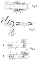
- the free end of a pulled arm (2) carries a rocket (4) on which a wheel (not shown) is rotatably mounted.
- the other end of the rocket (4) is integral with the end of a link (9).
- a shock absorber (3) is arranged between the pulled arm (2) and a body element (not shown) of the vehicle.
- the drawn arms (2) are interconnected by a deformable profile (5), in the form of a V-shaped gutter or any other open profile, placed transversely between the arms (2).
- a torsion means (6) consisting of a torsion tube (6 ') and a torsion bar (6'') is arranged parallel to the deformable profile (5) between a structural element (1) and a binocular (16) .
- the torsion bar (6 '') is arranged concentrically inside the torsion tube (6 ').
- the grooved ends of the torsion bar are connected respectively to the end of the torsion tube (6 '), located at the level of the binocular (16), and to the structural element (1) constituted by an element of the vehicle chassis.
- the pulled arm (2) is hollow and contains a mechanism (7) constituted by a link (9) and a lever (8) mutually secured by an articulation (9 ') allowing an angular displacement of the link (9) relative to the lever (8).
- the lever (8) is rigidly connected to the torsion tube (6 ').
- the link (9) can be made of folded sheet and has two branches.
- the rocket (4) secures the suspension arm (2) and the link (9).
- the rocket (4) is engaged and maintained, in a known manner, in holes drilled respectively in the arm (2) and in each branch of the link (9).
- the lever (8) is connected to its counterpart by an anti-roll stabilization bar (15) which extends parallel to the torsion tube (6 ').
- the middle of the anti-roll bar (15) is connected to the torsion means (6) of each half-train by the binocular (16).
- a bush (13) is arranged concentrically between the torsion bar (6 '') on the one hand and the torsion tube (6 ') on the other.
- the sleeve (13) is rigidly connected, by one of its ends, to the structural element (1) and constitutes the bearing of a bearing (10) integral with the torsion tube (6 ').
- This bearing (10) can be constituted by a needle bearing.
- a seal (14) is arranged at the end of the torsion tube (6 '') closest to the bearing (10).
- a vertical force F v exerted on the wheel spindle (4) generates an axial torsional torque C of axis A on the torsion tube (6 ').
- the torsion bar (6 '') takes up the torque C by its end secured to the torsion tube (6 ') and transmits it to the chassis element (1).
- a longitudinal force F effort applied to the wheel spindle (4) causes the rotation of the link (9) relative to the lever (8).
- the lever (8) being linked to the torsion tube (6 '), this results in a transfer of the longitudinal force F1 at the level of the elastic element (11) which deforms radially in the direction of the force.
- the elastic element (11) therefore does not take up the vertical forces applied to the wheel spindle (4), the latter being transmitted to the chassis element by the torsion tube (6 ') and the torsion bar (6 '').
- the elastic element (11) therefore does not undergo vertical preload and may therefore have only a slight radial stiffness, which allows optimal damping of the high frequency vibrations generated by the longitudinal forces applied to the rocket (4) of wheel, when the vehicle is running.
Landscapes
- Engineering & Computer Science (AREA)
- Mechanical Engineering (AREA)
- Vehicle Body Suspensions (AREA)
Applications Claiming Priority (2)
| Application Number | Priority Date | Filing Date | Title |
|---|---|---|---|
| FR9312609 | 1993-10-22 | ||
| FR9312609A FR2711582B1 (fr) | 1993-10-22 | 1993-10-22 | Suspension de train arrière pour véhicule automobile. |
Publications (1)
| Publication Number | Publication Date |
|---|---|
| EP0649764A1 true EP0649764A1 (de) | 1995-04-26 |
Family
ID=9452115
Family Applications (1)
| Application Number | Title | Priority Date | Filing Date |
|---|---|---|---|
| EP94402378A Withdrawn EP0649764A1 (de) | 1993-10-22 | 1994-10-21 | Hinterachsenaufhängung für ein Kraftfahrzeug |
Country Status (2)
| Country | Link |
|---|---|
| EP (1) | EP0649764A1 (de) |
| FR (1) | FR2711582B1 (de) |
Cited By (5)
| Publication number | Priority date | Publication date | Assignee | Title |
|---|---|---|---|---|
| FR2761301A1 (fr) * | 1997-03-28 | 1998-10-02 | Peugeot | Essieu arriere de vehicule automobile |
| EP0956984A1 (de) * | 1998-05-13 | 1999-11-17 | Compagnie Générale des Etablissements MICHELIN-MICHELIN & CIE | Fahrzeugachse, die mit torsionswirkenden Aufhängungselementen ausgerüstet ist |
| FR2829428A1 (fr) * | 2001-09-07 | 2003-03-14 | Peugeot Citroen Automobiles Sa | Train arriere perfectionne pour vehicule automobile du type a bras tires longitudinaux avec des barres de maintien ou de guidage transversal |
| WO2007112714A1 (de) * | 2006-03-30 | 2007-10-11 | Zf Friedrichshafen Ag | Radführende stabilisatoreinrichtung |
| EP2311670A1 (de) * | 2009-10-15 | 2011-04-20 | Ford Global Technologies, LLC | Aufhängungssystem |
Citations (7)
| Publication number | Priority date | Publication date | Assignee | Title |
|---|---|---|---|---|
| FR1002435A (fr) * | 1946-09-30 | 1952-03-06 | Ouest Parisien Soc Ind De L | Suspension perfectionnée pour véhicules et véhicules en comportant application |
| DE958720C (de) * | 1954-08-17 | 1957-02-21 | Auto Union G M B H | Hinterradabfederung, insbesondere fuer Kraftfahrzeuge |
| US3003782A (en) * | 1957-07-16 | 1961-10-10 | Albert F Hickman | Body roll stabilizer for motor trucks |
| FR2101344A5 (de) * | 1970-08-19 | 1972-03-31 | Bayerische Motoren Werke Ag | |
| FR2400441A1 (fr) * | 1977-08-16 | 1979-03-16 | Porsche Ag | Suspension d'essieu arriere |
| FR2544259A1 (fr) * | 1983-04-12 | 1984-10-19 | Renault | Suspension arriere a roues independantes pour vehicule automobile |
| EP0133829A1 (de) * | 1983-08-10 | 1985-03-06 | Regie Nationale Des Usines Renault | Unabhängige Hinterradaufhängung |
-
1993
- 1993-10-22 FR FR9312609A patent/FR2711582B1/fr not_active Expired - Fee Related
-
1994
- 1994-10-21 EP EP94402378A patent/EP0649764A1/de not_active Withdrawn
Patent Citations (7)
| Publication number | Priority date | Publication date | Assignee | Title |
|---|---|---|---|---|
| FR1002435A (fr) * | 1946-09-30 | 1952-03-06 | Ouest Parisien Soc Ind De L | Suspension perfectionnée pour véhicules et véhicules en comportant application |
| DE958720C (de) * | 1954-08-17 | 1957-02-21 | Auto Union G M B H | Hinterradabfederung, insbesondere fuer Kraftfahrzeuge |
| US3003782A (en) * | 1957-07-16 | 1961-10-10 | Albert F Hickman | Body roll stabilizer for motor trucks |
| FR2101344A5 (de) * | 1970-08-19 | 1972-03-31 | Bayerische Motoren Werke Ag | |
| FR2400441A1 (fr) * | 1977-08-16 | 1979-03-16 | Porsche Ag | Suspension d'essieu arriere |
| FR2544259A1 (fr) * | 1983-04-12 | 1984-10-19 | Renault | Suspension arriere a roues independantes pour vehicule automobile |
| EP0133829A1 (de) * | 1983-08-10 | 1985-03-06 | Regie Nationale Des Usines Renault | Unabhängige Hinterradaufhängung |
Cited By (9)
| Publication number | Priority date | Publication date | Assignee | Title |
|---|---|---|---|---|
| FR2761301A1 (fr) * | 1997-03-28 | 1998-10-02 | Peugeot | Essieu arriere de vehicule automobile |
| EP0956984A1 (de) * | 1998-05-13 | 1999-11-17 | Compagnie Générale des Etablissements MICHELIN-MICHELIN & CIE | Fahrzeugachse, die mit torsionswirkenden Aufhängungselementen ausgerüstet ist |
| US6145858A (en) * | 1998-05-13 | 2000-11-14 | Compagnie Generale Des Etablissements Michelin - Michelin & Cie | Vehicle axle equipped with torsional suspension elements |
| FR2829428A1 (fr) * | 2001-09-07 | 2003-03-14 | Peugeot Citroen Automobiles Sa | Train arriere perfectionne pour vehicule automobile du type a bras tires longitudinaux avec des barres de maintien ou de guidage transversal |
| WO2003022608A1 (fr) * | 2001-09-07 | 2003-03-20 | Peugeot Citroen Automobiles S.A. | Train arriere pour vehicule automobile du type a bras tires longitudinaux avec des barres de maintien ou de guidage transversal |
| US7229087B2 (en) | 2001-09-07 | 2007-06-12 | Peugeot Citroen Automobiles S.A. | Rear axle assembly for an automobile |
| WO2007112714A1 (de) * | 2006-03-30 | 2007-10-11 | Zf Friedrichshafen Ag | Radführende stabilisatoreinrichtung |
| US7651106B2 (en) | 2006-03-30 | 2010-01-26 | Zf Friedrichshafen Ag | Wheel-guiding stabilizer device |
| EP2311670A1 (de) * | 2009-10-15 | 2011-04-20 | Ford Global Technologies, LLC | Aufhängungssystem |
Also Published As
| Publication number | Publication date |
|---|---|
| FR2711582A1 (fr) | 1995-05-05 |
| FR2711582B1 (fr) | 1995-12-15 |
Similar Documents
| Publication | Publication Date | Title |
|---|---|---|
| FR2584658A1 (fr) | Suspension de roue arriere de vehicule a moteur | |
| EP0904211B1 (de) | Torsionsweiche achse mit einem querträger und längslenkern | |
| EP0279135B1 (de) | Aufhängungs- und Schwenkvorrichtung von einem lenkbaren Rad eines Kraftfahrzeuges | |
| FR2588217A1 (fr) | Suspension de roue arriere independante | |
| EP0389363B1 (de) | Kraftfahrzeughinterradsatz | |
| EP0394438A1 (de) | Aufhaengung eines motorrads | |
| FR2691930A1 (fr) | Essieu, notamment essieu arrière multibras de véhicule automobile. | |
| EP0685354B1 (de) | Radaufhängung mit Querblattfeder für Kraftfahrzeug | |
| FR2899154A1 (fr) | Dispositif de butee de suspension de vehicule | |
| FR2711582A1 (fr) | Suspension de train arrière pour véhicule automobile. | |
| FR2664537A1 (fr) | Palier elastique de bras oscillant pour des suspensions de roues de vehicules automobiles. | |
| FR2480683A1 (fr) | Dispositif de maintien transversal de la barre antidevers dans une suspension de vehicule automobile | |
| EP0830955B1 (de) | Aufhängungsvorrichtung, insbesondere für Kraftfahrzeuge | |
| EP0867318A1 (de) | Verbesserungen an einer Hinterachse eines Kraftfahrzeuges mit einem torsionsverformbaren Verbundlenker und vertikalen Aufhängungsfedern | |
| EP1378682A1 (de) | Hydroelastisches axialwirkendes Gelenk | |
| FR2645802A1 (fr) | Train arriere de suspension de vehicule automobile | |
| EP0914977B1 (de) | Hinterachse mit einer Gelenkvorrichtung zwischen einem oszillierenden Längslenker und dem Kraftfahrzeugaufbau | |
| FR2682326A1 (fr) | Suspension notamment a bras tire pour vehicule automobile, avec systeme d'amortissement des chocs longitudinaux. | |
| EP0712743B1 (de) | Antirollvorrichtung für Kraftfahrzeugachse | |
| FR2750925A1 (fr) | Suspension horizontale pour roue de vehicule automobile avec systeme de filtrage des chocs longitudinaux | |
| EP0007820B1 (de) | Verbesserung der Aufhängung eines Fahrzeugradsatzes | |
| FR2717124A1 (fr) | Train arrière de véhicule automobile. | |
| FR2717123A1 (fr) | Suspension pour roue de véhicule. | |
| FR2582591A1 (fr) | Suspension arriere a roue independante pour vehicules a moteur | |
| EP0061944B1 (de) | Radsatz für Fahrzeug |
Legal Events
| Date | Code | Title | Description |
|---|---|---|---|
| PUAI | Public reference made under article 153(3) epc to a published international application that has entered the european phase |
Free format text: ORIGINAL CODE: 0009012 |
|
| AK | Designated contracting states |
Kind code of ref document: A1 Designated state(s): BE DE ES GB IT |
|
| 17P | Request for examination filed |
Effective date: 19950927 |
|
| GRAG | Despatch of communication of intention to grant |
Free format text: ORIGINAL CODE: EPIDOS AGRA |
|
| 17Q | First examination report despatched |
Effective date: 19961029 |
|
| STAA | Information on the status of an ep patent application or granted ep patent |
Free format text: STATUS: THE APPLICATION HAS BEEN WITHDRAWN |
|
| 18W | Application withdrawn |
Withdrawal date: 19970227 |