EP0649946A2 - Procédé et dispositif de commande d'une soupape d'obturation - Google Patents
Procédé et dispositif de commande d'une soupape d'obturation Download PDFInfo
- Publication number
- EP0649946A2 EP0649946A2 EP94116591A EP94116591A EP0649946A2 EP 0649946 A2 EP0649946 A2 EP 0649946A2 EP 94116591 A EP94116591 A EP 94116591A EP 94116591 A EP94116591 A EP 94116591A EP 0649946 A2 EP0649946 A2 EP 0649946A2
- Authority
- EP
- European Patent Office
- Prior art keywords
- valve
- shut
- chamber
- pressure
- vacuum
- Prior art date
- Legal status (The legal status is an assumption and is not a legal conclusion. Google has not performed a legal analysis and makes no representation as to the accuracy of the status listed.)
- Granted
Links
Images



Classifications
-
- E—FIXED CONSTRUCTIONS
- E03—WATER SUPPLY; SEWERAGE
- E03F—SEWERS; CESSPOOLS
- E03F1/00—Methods, systems, or installations for draining-off sewage or storm water
- E03F1/006—Pneumatic sewage disposal systems; accessories specially adapted therefore
-
- Y—GENERAL TAGGING OF NEW TECHNOLOGICAL DEVELOPMENTS; GENERAL TAGGING OF CROSS-SECTIONAL TECHNOLOGIES SPANNING OVER SEVERAL SECTIONS OF THE IPC; TECHNICAL SUBJECTS COVERED BY FORMER USPC CROSS-REFERENCE ART COLLECTIONS [XRACs] AND DIGESTS
- Y10—TECHNICAL SUBJECTS COVERED BY FORMER USPC
- Y10S—TECHNICAL SUBJECTS COVERED BY FORMER USPC CROSS-REFERENCE ART COLLECTIONS [XRACs] AND DIGESTS
- Y10S137/00—Fluid handling
- Y10S137/907—Vacuum-actuated valves
-
- Y—GENERAL TAGGING OF NEW TECHNOLOGICAL DEVELOPMENTS; GENERAL TAGGING OF CROSS-SECTIONAL TECHNOLOGIES SPANNING OVER SEVERAL SECTIONS OF THE IPC; TECHNICAL SUBJECTS COVERED BY FORMER USPC CROSS-REFERENCE ART COLLECTIONS [XRACs] AND DIGESTS
- Y10—TECHNICAL SUBJECTS COVERED BY FORMER USPC
- Y10T—TECHNICAL SUBJECTS COVERED BY FORMER US CLASSIFICATION
- Y10T137/00—Fluid handling
- Y10T137/0318—Processes
- Y10T137/0324—With control of flow by a condition or characteristic of a fluid
- Y10T137/0379—By fluid pressure
-
- Y—GENERAL TAGGING OF NEW TECHNOLOGICAL DEVELOPMENTS; GENERAL TAGGING OF CROSS-SECTIONAL TECHNOLOGIES SPANNING OVER SEVERAL SECTIONS OF THE IPC; TECHNICAL SUBJECTS COVERED BY FORMER USPC CROSS-REFERENCE ART COLLECTIONS [XRACs] AND DIGESTS
- Y10—TECHNICAL SUBJECTS COVERED BY FORMER USPC
- Y10T—TECHNICAL SUBJECTS COVERED BY FORMER US CLASSIFICATION
- Y10T137/00—Fluid handling
- Y10T137/7287—Liquid level responsive or maintaining systems
- Y10T137/7313—Control of outflow from tank
- Y10T137/7316—Self-emptying tanks
-
- Y—GENERAL TAGGING OF NEW TECHNOLOGICAL DEVELOPMENTS; GENERAL TAGGING OF CROSS-SECTIONAL TECHNOLOGIES SPANNING OVER SEVERAL SECTIONS OF THE IPC; TECHNICAL SUBJECTS COVERED BY FORMER USPC CROSS-REFERENCE ART COLLECTIONS [XRACs] AND DIGESTS
- Y10—TECHNICAL SUBJECTS COVERED BY FORMER USPC
- Y10T—TECHNICAL SUBJECTS COVERED BY FORMER US CLASSIFICATION
- Y10T137/00—Fluid handling
- Y10T137/7722—Line condition change responsive valves
- Y10T137/7758—Pilot or servo controlled
- Y10T137/7762—Fluid pressure type
- Y10T137/7764—Choked or throttled pressure type
- Y10T137/7768—Pilot controls supply to pressure chamber
Definitions
- the invention relates to a method for actuating a shut-off valve and a control arrangement for actuating one according to the preambles of the independent claims 1 and 5.
- a corresponding vacuum sewer system comprises, as essential components, house connection shafts with a currentless control arrangement and shut-off or suction valves, a subsequent pipe system with systematically arranged high and low Low points as well as a vacuum station with waste water collection tanks, waste water pumps, vacuum pumps, measurement and control technology.
- shut-off valve Due to the mechanism present in the control arrangement, the shut-off valve is opened when the back pressure is present and the waste water is sucked off into the vacuum line.
- the valve closes depending on the time after a few seconds via spring force and vacuum.
- the wastewater itself collects at the lowest points in the piping system and is gradually pushed by the air flowing in over the following high points towards the vacuum station.
- the wastewater is then conveyed from the collection station of the vacuum station to the wastewater treatment plant using conventional wastewater pumps via a pressure and free fall line.
- the control arrangement assigned to the shut-off valve should allow automatic adaptation to the wastewater portions to be extracted and to the operating conditions in the drainage system.
- a control arrangement of the type described at the outset is known under the name "AIRVAC”.
- the time is controlled via the pressure-adjustable chamber, which is initially pressurized with atmospheric pressure.
- It is also disadvantageous that the suction time from the existing negative pressure The entire system is dependent in an unfavorable manner, since the opening times in turn depend on the prevailing negative pressure.
- Another disadvantage is that the second valve, which releases the negative pressure to the shut-off valve, can be opened at a low negative pressure, which, however, is not sufficient for suction. This increases the risk that wastewater can be lifted into the frost area of the line and freeze out there.
- a pneumatic control device for a shut-off valve on a vacuum sewage line is known.
- at least one control valve and a minimum vacuum valve are necessary in addition to a first valve actuated by a dynamic pressure and a structurally complex time control device.
- the time control device which, among other things, comprises a membrane piston with a hollow pin, which is guided in a guide bushing, in order to open or close the control valves, a complex construction or assembly is required.
- DE 38 23 515 A1 describes a suction gun by means of which waste water can be sucked out from a collecting container by means of negative pressure.
- a control valve is required which can be operated manually or automatically. So that the control valve can be closed when the negative pressure drops, whereby the shut-off valve is separated from the negative pressure and thus the negative pressure line can be shut off, the control valve has a valve piston, which acts on axially and / or radially spring-loaded balls depending on the position of the valve piston. which are necessary to close the control valve.
- the present invention is based on the problem of developing a method and a control arrangement of the type described above in such a way that a high level of operational reliability is ensured with a compact and structurally simple construction, with an essentially vacuum-independent time control taking place, i. That is, that after the back pressure has ceased to exist, the control arrangement closes the vacuum supply to the shut-off valve after a defined period of time. At the same time, it should be ensured that the valve controlling the vacuum to the shut-off valve always assumes a defined position at a vacuum, which ensures that wastewater can be drawn off via the shut-off valve.
- the suddenly changing state (OPEN / CLOSE or CLOSE / OPEN) of the valve is brought about by so-called adjustable limiters, which act as spring-loaded balls acting on the valve piston of the second valve in the manner described below.
- the spring force can be adjusted to allow opening or closing of the second valve or control valve only at previously defined vacuum values. This ensures that the waste water can only be lifted out of the storage space if there is sufficient negative pressure for suction. As a result, no waste water can be present in the frost area of the line leading to the shut-off valve.
- the abruptly changing state can be reactivated by means of a magnet, the forces acting directly or indirectly on the second valve change spontaneously when predetermined pressure conditions occur.
- the spring element acting on the valve piston of the second valve can be a spring which is arranged in the pressure-adjustable chamber or its region and exerts restoring forces on the valve piston.
- restoring forces can also be caused by a membrane fastened in the chamber, which is connected to the valve piston.
- the main task of such a membrane is to separate the chamber in terms of pressure from a first region, which can be connected to the negative pressure via the first valve, from a second region, which is always only subjected essentially to atmospheric pressure.
- the membrane performs a guiding function for the valve piston.
- first and second valves are arranged in a cylindrical housing having connections for the dynamic pressure and the negative pressure and a connection to the shut-off valve, the valve piston of the second valve being displaceably guided in a first housing section.
- elements which act radially on the valve piston and engage therein when the valve is closed or open can be arranged as limiters in the first housing section which accommodates the valve piston in an axially displaceable manner.
- the membrane connected to the valve piston of the second valve is held in a first position by means of a magnet or can be moved suddenly or largely suddenly from the first position into a second position or vice versa when the pressure or pressure in the chamber or its region has occurred , wherein in the first position the second valve shuts off the vacuum connection to the shut-off valve and in the second position releases the vacuum connection to the shut-off valve.
- the housing opening be connected to the first housing section receiving the valve piston of the second valve and, when the valve is closed, the Negative pressure to the shut-off valve blocking position of the second valve is connected in terms of pressure to the shut-off valve via the housing section.
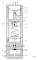
- the compact control arrangement (10 which operates without power, but pneumatically, consists of a cylindrical housing (12) in which a first valve (14) or release valve, which is connected via a membrane (16) by an opening (18) in the housing (12). back pressure is reached, and a second valve or control valve (20) are arranged.
- the valves (14) and (20) are arranged with their valve pistons (22) and (24) along the longitudinal axis of the housing (12).
- the valve piston (24) of the control valve (20) is guided in a bore (26) in an intermediate base (28) of the housing (12).
- Radially acting on the outer surface of the valve piston (24) are preferably three spring-loaded balls offset by 120 ° to one another, of which, for reasons of simplification, in principle two balls (30), (32) are shown, which can also be referred to as snap balls, and which engage in the circumferential annular grooves (34) and (36) in the end positions of the valve (20), that is to say with the valve (20) (FIGS. 1 and 2) or the valve (20) (FIGS. 3 and 4) open .
- the spring force acting on the balls (30) and (32) can be changed via adjusting elements (38) and (40).
- a spring element such as a coil spring (71) also acts on the valve piston (24) in the direction of the closed position of the valve (20).
- valve piston (24) is displaceably arranged with its valve plate (46) in a valve chamber (21). From the valve chamber (20) there is a connection (42) which is connected to a shut-off valve of the vacuum sewage system which can be controlled via the compact control arrangement (10) in order to pressurize it with vacuum in order to enable opening.
- connection (44) into the valve chamber (21) when the valve (20) is open, that is to say its valve disk (46) opens an opening (48) connected to the connection (44).
- connection (44) also leads a channel (50) running in the housing jacket, which opens into a tubular inner housing section (52) receiving the valve piston (22) of the first valve (14) or exhaust valve, in order to open the valve (14) to be connected to an inner chamber (56) via its valve chamber (54).
- valve (14) When the valve (14) is closed, the valve chamber (54) is closed with respect to the valve chamber (54) via a check valve (56).
- a diaphragm (72) extends from a cylindrical extension (70) of the valve piston (24) which extends in the chamber (56) and which faces the inner wall the housing (12) is sealed.
- valve (14) opens so that the negative pressure present at the connection (44) via the channel (50) can pass the valve piston (22) into the valve chamber (54) and the check valve opens, so that a vacuum is present in the chamber (56) (Fig. 2).
- the control valve (20) opens abruptly and via the opening (48) connects to the connection (42) to the shut-off valve, so that this reaches a vacuum required to open the shut-off valve.
- the waste water accumulated in the collecting container can be sucked off (Fig. 3).
- the control valve (20) can thus suddenly switch back to the closed position (basic position according to FIG. 1). At this moment, the vacuum is interrupted via the connection (42) to the shut-off valve. Via the opening (68), the bore (26) surrounding the valve piston (24), the valve chamber (21) and the connection (42), pressure equalization continues to the shut-off valve so that it can close again.
- valves (14) and (20) Due to the arrangement of the valves (14) and (20) within the cylindrical housing (12) and the course of the control channels (50), (66) within the housing wall and the guiding of the valve pistons (22) and (24) in the intermediate floors ( 28) and (60) or from these tubular guides (52) a compact structure is ensured.
- the adjustable speed of the reduction of the negative pressure in the chamber (56) together with the spring (71) or the ball snappers (30), (32) provides a mechanical timer with a high level of functionality, with defined opening times of the shut-off valve without overlaps .
- Another essential feature is the limiter realized by the snap balls, which ensures that, on the one hand, a sudden change in the state of the second valve occurs and, on the other hand, the valve can only be opened and thus the shut-off valve can be pressurized if the vacuum in the sewage system is sufficient, also really convey waste water through the shutoff valve.
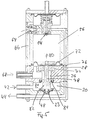
- FIG. 5 An alternative embodiment of a control arrangement corresponding to the structure and function of FIGS. 1 to 4 is shown in principle in FIG. 5. In principle, the same elements are provided with the same reference symbols.
- the second valve (20) In order also to allow the second valve (20) to switch suddenly from its open to its closed position, i. H. to shut off the initially existing connection between the vacuum connection (44) and the connection (42) to a shut-off valve (not shown) (illustration in FIG. 5), no limiters realized by snap balls are provided. Instead, the second valve (20) is switched over spontaneously by means of a magnet (74) and a plate (76) assigned to it.
- a magnet (74) is arranged in a stationary manner in the housing section (28) of the control arrangement, specifically coaxially with the valve piston (78) of the second valve (20). Opposite the magnet (74) there is a metal plate (76) which is connected to the membrane (72) which in turn starts from the inner wall of the chamber (56).
- valve (20) ie the valve head (23)
- the valve (20) can then be spontaneously lifted from the opening (48) leading to the negative pressure connection (44) when the negative pressure prevailing in the chamber (56) leads to the metal plate (76) force acting on the magnet (74) is overcome.
- the valve piston moves in the direction of the arrow (80) to open the valve (20), so that there is a position which corresponds to FIGS. 3 and 4.
- the holding force can be changed by the size of the metal plate (76), which in turn allows the time of the sudden opening of the valve (20) depending on the negative pressure prevailing in the chamber (56).
- the valve (20) is basically also closed abruptly when the valve (14) is closed and via the opening (68) and the line (66) and the throttle (64) which can be replaced in the exemplary embodiment in FIG ) Atmospheric pressure flows into the chamber (56). This results in a pressure build-up whereby the valve piston (78) is moved to its closed position to a certain extent due to the spring force caused by the membrane (72), and then when the force acting on the plate (76) from the magnet (74) is sufficient to pull the plate (76) against the magnet (74) to cause a sudden changeover of the valve (20).
- the valve (20) does not spontaneously switch from its upper end position to its lower closed end position from the beginning. Rather, the piston (78) is first slowly moved against the direction of the Pfeisl (80). In order to avoid that during this lifting movement an undesired overlap to the negative pressure led via the connection (42) to the shut-off valve and to the atmospheric pressure flowing through the opening (68) and the annular space (26) which coaxially surrounds the valve piston (78) takes place, the valve piston (78) on the valve seat side has a cylindrical extension (82) which, when the valve (20) is open, comes to rest against a circumferential seal (84), around the opening (68) to the atmosphere opposite the To lock chamber (21), which is in the connection between the vacuum connection (44) and the shut-off valve connection (42).
- the axial extension of the cylindrical extension (82) with respect to the seal (84) is chosen so that sealing takes place only until the time when the plate (76) is gripped by the magnet (74) and attracted by it becomes.
- valve head (23) bears against the valve seat (48), there is a connection between the connection (68) and the chamber (21) via the ring channel (26), since in this case the valve piston (78) is spaced apart from the seal (84 ) runs.
Landscapes
- Health & Medical Sciences (AREA)
- Life Sciences & Earth Sciences (AREA)
- Engineering & Computer Science (AREA)
- Hydrology & Water Resources (AREA)
- Public Health (AREA)
- Water Supply & Treatment (AREA)
- Sewage (AREA)
- Fluid-Driven Valves (AREA)
- Safety Valves (AREA)
Applications Claiming Priority (2)
| Application Number | Priority Date | Filing Date | Title |
|---|---|---|---|
| DE4336020A DE4336020C2 (de) | 1993-10-22 | 1993-10-22 | Steueranordnung für ein durch Unterdruck betätigbares Absperrventil |
| DE4336020 | 1993-10-22 |
Publications (3)
| Publication Number | Publication Date |
|---|---|
| EP0649946A2 true EP0649946A2 (fr) | 1995-04-26 |
| EP0649946A3 EP0649946A3 (fr) | 1996-07-31 |
| EP0649946B1 EP0649946B1 (fr) | 2001-05-02 |
Family
ID=6500732
Family Applications (1)
| Application Number | Title | Priority Date | Filing Date |
|---|---|---|---|
| EP94116591A Expired - Lifetime EP0649946B1 (fr) | 1993-10-22 | 1994-10-21 | Procédé et dispositif de commande d'une soupape d'obturation |
Country Status (4)
| Country | Link |
|---|---|
| US (1) | US5657784A (fr) |
| EP (1) | EP0649946B1 (fr) |
| JP (1) | JPH07198052A (fr) |
| DE (2) | DE4336020C2 (fr) |
Cited By (9)
| Publication number | Priority date | Publication date | Assignee | Title |
|---|---|---|---|---|
| EP0829584A3 (fr) * | 1996-09-13 | 1998-11-18 | Roediger Anlagenbau GmbH | Arrangement pour pomper des liquides |
| DE19829391A1 (de) * | 1998-07-01 | 2000-01-13 | Roediger Anlagenbau | Vakuum- bzw. Unterdruckabsauganlage |
| EP0937830A3 (fr) * | 1998-02-19 | 2000-02-02 | ROEDIGER VAKUUM- und HAUSTECHNIK GmbH | Système de vidange par aspiration ou évacuation |
| DE10216091C1 (de) * | 2002-04-11 | 2003-08-14 | Roediger Vakuum & Haustechnik | Überwachungsanordnung |
| DE102006028732A1 (de) * | 2006-06-20 | 2008-01-03 | Roediger Vakuum- Und Haustechnik Gmbh | Steueranordnung |
| DE10361439B4 (de) * | 2002-12-23 | 2010-09-23 | Roediger Vacuum Gmbh | Verfahren zum Absaugen von Abwaser und Unterdruckabwassersystem |
| EP2363542A2 (fr) | 2010-03-02 | 2011-09-07 | Roediger Vacuum GmbH | Agencement de commande |
| DE102010016524A1 (de) | 2010-04-19 | 2011-10-20 | Roediger Vacuum Gmbh | Verfahren zum Überwachen und Steuern von Komponenten eines Unterdruckabwassersystems |
| NL1037986C2 (nl) * | 2010-05-27 | 2011-11-29 | Klaas Dirk Heide | Sanitaire eenheid voor een vaartuig of voertuig en tank voor een dergelijke sanitaire eenheid. |
Families Citing this family (11)
| Publication number | Priority date | Publication date | Assignee | Title |
|---|---|---|---|---|
| DE19546650B4 (de) * | 1995-12-14 | 2005-02-24 | Roediger Vakuum- Und Haustechnik Gmbh | Anordnung zur zeitlichen Begrenzung der Ansteuerung eines durch Unterdruck betätigbaren Pneumatikventils |
| US6467494B1 (en) * | 1999-08-18 | 2002-10-22 | Roediger Vakuum- Und Haustechnik Gmbh | Arrangement in a vacuum sewer system for preventing water entering a pneumatic controller through a breather line |
| EP1091053A1 (fr) * | 1999-10-05 | 2001-04-11 | ROEDIGER VAKUUM- und HAUSTECHNIK GmbH | Dispositif de commande pour une vanne d'obturation actionnée par dépression et méthode de commande de la vanne |
| DE10006028C1 (de) * | 2000-02-10 | 2001-05-23 | Roediger Vakuum & Haustechnik | Verfahren und Anordnung zum Belüften eines Flüssigkeit aufnehmenden Behälters |
| US6672565B2 (en) * | 2000-04-03 | 2004-01-06 | Larry R. Russell | Dual snap action for valves |
| EP1462689A1 (fr) * | 2003-03-26 | 2004-09-29 | Luxembourg Patent Company S.A. | Robinet pour bouteille de gaz |
| DE102006015480B3 (de) * | 2006-03-24 | 2007-10-11 | Roediger Vakuum- Und Haustechnik Gmbh | Verschlusseinrichtung einer Unterdruckabwasseranlage und Unterdruckabwasseranlage |
| US10001787B2 (en) | 2014-06-02 | 2018-06-19 | Aqseptence Group, Inc. | Controller for vacuum sewage system |
| CN106352124B (zh) * | 2016-08-30 | 2018-10-12 | 宁波亚德客自动化工业有限公司 | 定压阀 |
| US10288189B2 (en) * | 2017-09-07 | 2019-05-14 | Acorn Engineering Company | Pneumatic controller |
| CN111965039B (zh) * | 2020-08-25 | 2022-06-10 | 贵州大学 | 一种研究动/静水压对岩石力学性质的影响的实验装置 |
Family Cites Families (10)
| Publication number | Priority date | Publication date | Assignee | Title |
|---|---|---|---|---|
| US2620825A (en) * | 1943-09-25 | 1952-12-09 | Joseph G Cannon | Automatic cycling valve |
| US3174500A (en) * | 1962-06-29 | 1965-03-23 | Caterpillar Tractor Co | Snap acting accumulator charging valve |
| US3998736A (en) * | 1976-05-12 | 1976-12-21 | Greenleaf Jr John W | Sewage disposal system |
| US4366834A (en) * | 1980-10-10 | 1983-01-04 | Sargent-Welch Scientific Company | Back-flow prevention valve |
| DE3409673A1 (de) * | 1984-03-16 | 1985-09-19 | Friedrich 3300 Braunschweig Gries | Schnellschlussventil mit mebrangesteuertem dauermagnet |
| DE3727661C2 (de) * | 1987-08-19 | 1996-02-08 | Harald Michael | Pneumatische Steuervorrichtung für ein Absperrventil an einer Unterdruck-Abwasserleitung |
| DE3823515A1 (de) * | 1988-05-10 | 1989-11-23 | Harald Michael | Steuervorrichtung fuer ein durch unterdruck betaetigbares absaugventil an einer vakuumleitung, insbesondere fuer abwasser |
| JPH0388621A (ja) * | 1989-08-31 | 1991-04-15 | Ebara Corp | 真空式汚水収集装置及び該装置用真空弁コントローラ |
| US5269337A (en) * | 1990-03-27 | 1993-12-14 | Aaron Goldsmith | Water control apparatus |
| US5048558A (en) * | 1990-05-21 | 1991-09-17 | Calhoun Carl R | Valve seat and method of repair |
-
1993
- 1993-10-22 DE DE4336020A patent/DE4336020C2/de not_active Expired - Fee Related
-
1994
- 1994-10-20 US US08/326,214 patent/US5657784A/en not_active Expired - Lifetime
- 1994-10-21 EP EP94116591A patent/EP0649946B1/fr not_active Expired - Lifetime
- 1994-10-21 DE DE59409737T patent/DE59409737D1/de not_active Expired - Lifetime
- 1994-10-24 JP JP6284361A patent/JPH07198052A/ja active Pending
Cited By (17)
| Publication number | Priority date | Publication date | Assignee | Title |
|---|---|---|---|---|
| EP0829584A3 (fr) * | 1996-09-13 | 1998-11-18 | Roediger Anlagenbau GmbH | Arrangement pour pomper des liquides |
| EP0937830A3 (fr) * | 1998-02-19 | 2000-02-02 | ROEDIGER VAKUUM- und HAUSTECHNIK GmbH | Système de vidange par aspiration ou évacuation |
| DE19829391A1 (de) * | 1998-07-01 | 2000-01-13 | Roediger Anlagenbau | Vakuum- bzw. Unterdruckabsauganlage |
| DE19829391C2 (de) * | 1998-07-01 | 2001-03-08 | Roediger Vakuum & Haustechnik | Vakuum- bzw. Unterdruckabsauganlage |
| DE10216091C1 (de) * | 2002-04-11 | 2003-08-14 | Roediger Vakuum & Haustechnik | Überwachungsanordnung |
| DE10361439B4 (de) * | 2002-12-23 | 2010-09-23 | Roediger Vacuum Gmbh | Verfahren zum Absaugen von Abwaser und Unterdruckabwassersystem |
| DE102006028732A1 (de) * | 2006-06-20 | 2008-01-03 | Roediger Vakuum- Und Haustechnik Gmbh | Steueranordnung |
| DE102006028732B4 (de) * | 2006-06-20 | 2009-10-15 | Roediger Vacuum Gmbh | Steueranordnung |
| EP2363542A2 (fr) | 2010-03-02 | 2011-09-07 | Roediger Vacuum GmbH | Agencement de commande |
| DE102010000609A1 (de) | 2010-03-02 | 2011-09-08 | Roediger Vacuum Gmbh | Steueranordnung |
| US8418715B2 (en) | 2010-03-02 | 2013-04-16 | Roediger Vacuum Gmbh | Control system |
| EP2363542A3 (fr) * | 2010-03-02 | 2013-07-17 | Roediger Vacuum GmbH | Agencement de commande |
| DE102010000609B4 (de) * | 2010-03-02 | 2015-03-12 | Roediger Vacuum Gmbh | Steueranordnung |
| DE102010016524A1 (de) | 2010-04-19 | 2011-10-20 | Roediger Vacuum Gmbh | Verfahren zum Überwachen und Steuern von Komponenten eines Unterdruckabwassersystems |
| DE102010016524B4 (de) * | 2010-04-19 | 2013-10-17 | Roediger Vacuum Gmbh | Verfahren zum Überwachen und Steuern von Komponenten eines Unterdruckabwassersystems |
| NL1037986C2 (nl) * | 2010-05-27 | 2011-11-29 | Klaas Dirk Heide | Sanitaire eenheid voor een vaartuig of voertuig en tank voor een dergelijke sanitaire eenheid. |
| WO2011149342A1 (fr) * | 2010-05-27 | 2011-12-01 | Klaas-Dirk Van Der Heide | Unité sanitaire pour navire ou véhicule, et réservoir pour une telle unité sanitaire |
Also Published As
| Publication number | Publication date |
|---|---|
| DE4336020C2 (de) | 1997-05-15 |
| DE59409737D1 (de) | 2001-06-07 |
| DE4336020A1 (de) | 1995-04-27 |
| EP0649946A3 (fr) | 1996-07-31 |
| EP0649946B1 (fr) | 2001-05-02 |
| JPH07198052A (ja) | 1995-08-01 |
| US5657784A (en) | 1997-08-19 |
Similar Documents
| Publication | Publication Date | Title |
|---|---|---|
| EP0649946B1 (fr) | Procédé et dispositif de commande d'une soupape d'obturation | |
| DE29706717U1 (de) | Breitbandventil | |
| EP0825303A1 (fr) | Moyens de commande d'une vanne de décharge et/ou de chasse d'eau à dépression | |
| EP0659947B1 (fr) | Dispositif de commande pour une vanne d'obturation actionnée par dépression | |
| DE10026843B4 (de) | Steueranordnung für ein durch Unterdruck betätigbares Absperrventil sowie ein Verfahren zum Steuern eines solchen | |
| EP3241749A1 (fr) | Système et procédé d'élimination de fluide à partir d'un évier | |
| EP0130306B2 (fr) | Procédé et dispositif pour contrôler un séparateur de tubes | |
| EP0341595B1 (fr) | Dispositif de commande pour une vanne d'aspiration actionnée par dépression d'une conduite sous vide, particulièrement pour eaux d'égouts | |
| EP0239892B1 (fr) | Procédé et dispositif pour actionner une installation d'évacuation d'eaux usées par dépression | |
| EP0278333B1 (fr) | Dispositif de commande pour un séparateur de tuyau | |
| EP0195389B2 (fr) | Déconnecteur de tuyaux | |
| EP0621066B1 (fr) | Installation de filtre de rinçage à contre-courant | |
| EP0216101B1 (fr) | Dispositif de contrôle pneumatique pour une soupape d'arrêt d'un conduit d'eaux usées à vide | |
| EP0240728B1 (fr) | Tuyau à dispositif de séparation | |
| WO2004092591A1 (fr) | Soupape de distribution a variation continue | |
| DE8524447U1 (de) | Pneumatische Steuervorrichtung für ein Absperrventil einer Vakuum-Abwasserleitung | |
| DE8206970U1 (de) | Vorrichtung zum absperren und belueften einer rohrleitung | |
| DE2116991A1 (de) | Spulvorrichtung eines Wasserklosetts | |
| CH656445A5 (en) | Device for blocking and venting a pipeline | |
| DE8532297U1 (de) | Pneumatische Steuervorrichtung für ein Absperrventil einer Vakuum-Abwasserleitung | |
| DD213254A1 (de) | Rueckflussverhinderungseinrichtung an hydranten | |
| WO1991006716A1 (fr) | Dispositif antiretour destine a etre monte en particulier sur les conduites d'eau potable | |
| DE3037061A1 (de) | Mengenregelventil | |
| DE7522540U (de) | Regelventil | |
| DE2352325B2 (de) | Kondensatableiter |
Legal Events
| Date | Code | Title | Description |
|---|---|---|---|
| PUAI | Public reference made under article 153(3) epc to a published international application that has entered the european phase |
Free format text: ORIGINAL CODE: 0009012 |
|
| AK | Designated contracting states |
Kind code of ref document: A2 Designated state(s): DE FR GB NL SE |
|
| RAX | Requested extension states of the european patent have changed |
Free format text: SI |
|
| RBV | Designated contracting states (corrected) |
Designated state(s): DE FR GB NL SE |
|
| PUAL | Search report despatched |
Free format text: ORIGINAL CODE: 0009013 |
|
| AK | Designated contracting states |
Kind code of ref document: A3 Designated state(s): DE FR GB NL SE |
|
| AX | Request for extension of the european patent |
Free format text: SI |
|
| 17P | Request for examination filed |
Effective date: 19960809 |
|
| 17Q | First examination report despatched |
Effective date: 19990707 |
|
| RAP1 | Party data changed (applicant data changed or rights of an application transferred) |
Owner name: ROEDIGER VAKUUM- UND HAUSTECHNIK GMBH |
|
| GRAG | Despatch of communication of intention to grant |
Free format text: ORIGINAL CODE: EPIDOS AGRA |
|
| GRAG | Despatch of communication of intention to grant |
Free format text: ORIGINAL CODE: EPIDOS AGRA |
|
| GRAG | Despatch of communication of intention to grant |
Free format text: ORIGINAL CODE: EPIDOS AGRA |
|
| GRAH | Despatch of communication of intention to grant a patent |
Free format text: ORIGINAL CODE: EPIDOS IGRA |
|
| GRAH | Despatch of communication of intention to grant a patent |
Free format text: ORIGINAL CODE: EPIDOS IGRA |
|
| GRAA | (expected) grant |
Free format text: ORIGINAL CODE: 0009210 |
|
| AK | Designated contracting states |
Kind code of ref document: B1 Designated state(s): DE FR GB NL SE |
|
| REF | Corresponds to: |
Ref document number: 59409737 Country of ref document: DE Date of ref document: 20010607 |
|
| GBT | Gb: translation of ep patent filed (gb section 77(6)(a)/1977) |
Effective date: 20010723 |
|
| ET | Fr: translation filed | ||
| REG | Reference to a national code |
Ref country code: GB Ref legal event code: IF02 |
|
| PLBE | No opposition filed within time limit |
Free format text: ORIGINAL CODE: 0009261 |
|
| STAA | Information on the status of an ep patent application or granted ep patent |
Free format text: STATUS: NO OPPOSITION FILED WITHIN TIME LIMIT |
|
| 26N | No opposition filed | ||
| PGFP | Annual fee paid to national office [announced via postgrant information from national office to epo] |
Ref country code: FR Payment date: 20121113 Year of fee payment: 19 Ref country code: DE Payment date: 20121023 Year of fee payment: 19 |
|
| PGFP | Annual fee paid to national office [announced via postgrant information from national office to epo] |
Ref country code: SE Payment date: 20121024 Year of fee payment: 19 Ref country code: GB Payment date: 20121024 Year of fee payment: 19 |
|
| PGFP | Annual fee paid to national office [announced via postgrant information from national office to epo] |
Ref country code: NL Payment date: 20121018 Year of fee payment: 19 |
|
| REG | Reference to a national code |
Ref country code: NL Ref legal event code: V1 Effective date: 20140501 |
|
| REG | Reference to a national code |
Ref country code: SE Ref legal event code: EUG |
|
| GBPC | Gb: european patent ceased through non-payment of renewal fee |
Effective date: 20131021 |
|
| PG25 | Lapsed in a contracting state [announced via postgrant information from national office to epo] |
Ref country code: GB Free format text: LAPSE BECAUSE OF NON-PAYMENT OF DUE FEES Effective date: 20131021 |
|
| REG | Reference to a national code |
Ref country code: FR Ref legal event code: ST Effective date: 20140630 |
|
| REG | Reference to a national code |
Ref country code: DE Ref legal event code: R119 Ref document number: 59409737 Country of ref document: DE Effective date: 20140501 |
|
| PG25 | Lapsed in a contracting state [announced via postgrant information from national office to epo] |
Ref country code: DE Free format text: LAPSE BECAUSE OF NON-PAYMENT OF DUE FEES Effective date: 20140501 Ref country code: NL Free format text: LAPSE BECAUSE OF NON-PAYMENT OF DUE FEES Effective date: 20140501 Ref country code: FR Free format text: LAPSE BECAUSE OF NON-PAYMENT OF DUE FEES Effective date: 20131031 Ref country code: SE Free format text: LAPSE BECAUSE OF NON-PAYMENT OF DUE FEES Effective date: 20131022 |