EP0649976A1 - Brennkraftmaschine - Google Patents
Brennkraftmaschine Download PDFInfo
- Publication number
- EP0649976A1 EP0649976A1 EP94115197A EP94115197A EP0649976A1 EP 0649976 A1 EP0649976 A1 EP 0649976A1 EP 94115197 A EP94115197 A EP 94115197A EP 94115197 A EP94115197 A EP 94115197A EP 0649976 A1 EP0649976 A1 EP 0649976A1
- Authority
- EP
- European Patent Office
- Prior art keywords
- intake
- valve
- fuel
- fuel injection
- internal combustion
- Prior art date
- Legal status (The legal status is an assumption and is not a legal conclusion. Google has not performed a legal analysis and makes no representation as to the accuracy of the status listed.)
- Granted
Links
- 238000002485 combustion reaction Methods 0.000 title claims abstract description 50
- 239000000446 fuel Substances 0.000 claims abstract description 100
- 238000002347 injection Methods 0.000 claims abstract description 61
- 239000007924 injection Substances 0.000 claims abstract description 61
- 238000000889 atomisation Methods 0.000 abstract description 6
- 230000033001 locomotion Effects 0.000 description 16
- 238000002474 experimental method Methods 0.000 description 10
- 230000004044 response Effects 0.000 description 5
- 239000000498 cooling water Substances 0.000 description 3
- 239000000203 mixture Substances 0.000 description 3
- 229930195733 hydrocarbon Natural products 0.000 description 2
- 150000002430 hydrocarbons Chemical class 0.000 description 2
- 230000006872 improvement Effects 0.000 description 2
- 238000004519 manufacturing process Methods 0.000 description 2
- 230000007246 mechanism Effects 0.000 description 2
- 230000009467 reduction Effects 0.000 description 2
- 230000004043 responsiveness Effects 0.000 description 2
- 238000005096 rolling process Methods 0.000 description 2
- 230000002411 adverse Effects 0.000 description 1
- 230000015572 biosynthetic process Effects 0.000 description 1
- 239000003054 catalyst Substances 0.000 description 1
- 230000003197 catalytic effect Effects 0.000 description 1
- 230000006835 compression Effects 0.000 description 1
- 238000007906 compression Methods 0.000 description 1
- 230000008021 deposition Effects 0.000 description 1
- 238000001514 detection method Methods 0.000 description 1
- 238000010586 diagram Methods 0.000 description 1
- 230000002708 enhancing effect Effects 0.000 description 1
- 238000012986 modification Methods 0.000 description 1
- 230000004048 modification Effects 0.000 description 1
- 238000000746 purification Methods 0.000 description 1
- 230000003584 silencer Effects 0.000 description 1
- 238000000638 solvent extraction Methods 0.000 description 1
- 238000011144 upstream manufacturing Methods 0.000 description 1
Images


Classifications
-
- F—MECHANICAL ENGINEERING; LIGHTING; HEATING; WEAPONS; BLASTING
- F01—MACHINES OR ENGINES IN GENERAL; ENGINE PLANTS IN GENERAL; STEAM ENGINES
- F01L—CYCLICALLY OPERATING VALVES FOR MACHINES OR ENGINES
- F01L1/00—Valve-gear or valve arrangements, e.g. lift-valve gear
- F01L1/26—Valve-gear or valve arrangements, e.g. lift-valve gear characterised by the provision of two or more valves operated simultaneously by same transmitting-gear; peculiar to machines or engines with more than two lift-valves per cylinder
- F01L1/267—Valve-gear or valve arrangements, e.g. lift-valve gear characterised by the provision of two or more valves operated simultaneously by same transmitting-gear; peculiar to machines or engines with more than two lift-valves per cylinder with means for varying the timing or the lift of the valves
-
- F—MECHANICAL ENGINEERING; LIGHTING; HEATING; WEAPONS; BLASTING
- F02—COMBUSTION ENGINES; HOT-GAS OR COMBUSTION-PRODUCT ENGINE PLANTS
- F02D—CONTROLLING COMBUSTION ENGINES
- F02D41/00—Electrical control of supply of combustible mixture or its constituents
- F02D41/30—Controlling fuel injection
- F02D41/32—Controlling fuel injection of the low pressure type
- F02D41/34—Controlling fuel injection of the low pressure type with means for controlling injection timing or duration
- F02D41/345—Controlling injection timing
-
- Y—GENERAL TAGGING OF NEW TECHNOLOGICAL DEVELOPMENTS; GENERAL TAGGING OF CROSS-SECTIONAL TECHNOLOGIES SPANNING OVER SEVERAL SECTIONS OF THE IPC; TECHNICAL SUBJECTS COVERED BY FORMER USPC CROSS-REFERENCE ART COLLECTIONS [XRACs] AND DIGESTS
- Y02—TECHNOLOGIES OR APPLICATIONS FOR MITIGATION OR ADAPTATION AGAINST CLIMATE CHANGE
- Y02T—CLIMATE CHANGE MITIGATION TECHNOLOGIES RELATED TO TRANSPORTATION
- Y02T10/00—Road transport of goods or passengers
- Y02T10/10—Internal combustion engine [ICE] based vehicles
- Y02T10/40—Engine management systems
Definitions
- the present invention relates to an internal combustion engine having a valve operating device operatively connected to a pair of intake valves and capable of opening and closing one of the intake valves in accordance with an operating condition of the engine while only opening and closing the other intake valve in a small lift amount, thereby producing a deflection of the intake air drawn into the combustion chamber, and a fuel injection valve for injecting the fuel toward intake valve bores independently opened and closed by the intake valves.
- the timing of opening and closing of the intake valve opened and closed in the small lift amount is set in a second half of an intake stroke, thereby eliminating an adverse influence on the production of a swirl due to the opening of the other intake valve.
- the flow speed of the intake air drawn into the combustion chamber at the time of the opening of the intake valve is higher in a first half of the intake stroke and lower in the second half.
- the opening and closing timing is set in the second half of the intake stroke, as in the above-described prior art.
- an internal combustion engine comprising: a valve operating device operatively connected to a pair of intake valves and capable of opening and closing one of the intake valves in accordance with an operating condition of the engine while only opening and closing the other intake valve in a small lift amount, thereby producing a deflection of the intake air drawn into the combustion chamber; and a fuel injection valve for injecting the fuel toward intake valve bores independently opened and closed by the intake valves, respectively; wherein the timing of the opening and closing of the intake valve which is opened and closed only in the small lift amount is set at a time point such that the lift amount is maximized in the first half of the intake stroke.
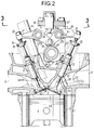
- the essential portions of an engine body in an single overhead cam (SOHC) type multi-cylinder internal combustion engine are a cylinder head 2 coupled to an upper surface of a cylinder block 1 and a piston 4 slidably received in each of a plurality of cylinders 3 provided in the cylinder block 1.
- the piston 4 has recess 4a in its upper surface.
- a combustion chamber 5 is defined between the upper surface of each of the pistons 4 and the cylinder head 2.
- a pair of intake valve bores 61 and 62 and a pair of exhaust valve bores 71 and 72 are provided in the cylinder head 2 that open into a ceiling surface of the combustion chamber 5.
- the intake valve bores 61 and 62 communicate with a single intake port 8 that opens into one side of the cylinder head 2, while the exhaust valve bores 71 and 72 communicate with a single exhaust port 9 that opens into the other side of the cylinder head 2.
- a pair of intake valves V I1 and V I2 capable of independently opening and closing the intake valve bores 61 and 62, respectively are slidably fitted in a pair of guide sleeves 10 disposed in the cylinder head 2.
- a retainer 12 is fixed to an upper end of each of the intake valves V I1 and V I2 which projects from the guide sleeve 10.
- a coiled valve spring 13 is interposed between each of the retainers 12 and the cylinder head 2 to surround a corresponding one of the intake valves V I1 and V I2 , so that each of the intake valves V I1 and V I2 is biased upwardly, i.e., in a closing direction by the corresponding valve spring 13.
- a pair of exhaust valves V E1 and V E2 capable of independently opening and closing the exhaust valve bores 71 and 72, respectively, are slidably fitted in a pair of guide sleeves 11 disposed in the cylinder head 2.
- a retainer 14 is fixed to an upper end of each of the exhaust valves V E1 and V E2 which projects from the guide sleeve 11.
- a coiled valve spring 15 is interposed between each of the retainers 14 and the cylinder head 2 to surround a corresponding one of the exhaust valves V E1 and V E2 , so that each of the exhaust valves V E1 and V E2 is biased upwardly, i.e., in a closing direction by the corresponding valve spring 15.
- a valve operating device 16 is provided in the cylinder head 2 for operating the intake valves V I1 and V I2 and the exhaust valves V E1 and V E2 .
- the valve operating device 16 includes a single cam shaft 17 operatively connected at a reduction ratio of 1/2 to a crankshaft which is not shown, first, second and third intake-side rocker arms 18, 19 and 20 for converting the rotating motion of the cam shaft 17 into opening and closing motions of the intake valves V I1 and V I2 , and a pair of exhaust-side rocker arms 21, 21 for converting the rotating motion of the cam shaft 17 into opening and closing motions of the exhaust valves V E1 and V E2 .
- the cam shaft 17 is rotatably carried by the cylinder head 2 and holders 22 coupled onto the cylinder head 2 on opposite sides of the cylinder 3 along an axis parallel to the axis of the crankshaft, and has a horizontal axis perpendicular to the axis of the cylinder 3.
- the cam shaft 17 is integrally provided with a first intake-side opening and closing cam 23 having a shape corresponding to a low-speed operation of the engine, a second intake-side opening and closing cam 24 disposed adjacent one side of the first intake-side opening and closing cam 23 and having a shape corresponding to a high-speed operation of the engine, and a slight-operating cam 25 disposed adjacent one side of the second intake-side opening and closing cam 24.
- the camshaft 17 is also integrally provided with exhaust-side opening and closing cams 26, 26 disposed on opposite sides of the first intake-side opening and closing cam 23 and the slight-operating cam 25.
- the first intake-side rocker arm 18 is operatively connected to one of the intake valves V I1
- the third intake-side rocker arm 20 is operatively connected to the other intake valve V I2
- the second intake-side rocker arm 19 is disposed between the first and third intake-side rocker arms 18 and 20 and is capable of being free to pivot with respect to the intake valves V I1 and V I2 .
- the intake-side rocker arms 18, 19 and 20 are swingably carried on an intake-side rocker shaft 27 I .
- the exhaust-side rocker arms 21, 21 are independently operatively connected to the exhaust valves V E1 and V E2 and are swingably carried on an exhaust-side rocker shaft 27 E .
- a roller 28 is rotably mounted by a pin (not shown or numbered) or the like on one end of the first intake-side rocker arm 18 to be in rolling contact with the first intake-side opening and closing cam 23.
- One end of each of the second and third intake-side rocker arms 19 and 20 are in sliding contact with the second intake-side opening and closing cam 24 and the slight-operating cam 25, respectively.
- Rollers 30, 30 are rotatably mounted by pins (not shown or numbered) or the like at one end of each of the exhaust-side rocker arms 21, 21 to be in rolling contact with the exhaust-side opening and closing cams 26, 26, respectively.
- Tappet screws 31, 31 are threadedly fitted into the other ends of the first and third intake-side rocker arms 18 and 20 for advancing and retracting adjustment movements to abut against upper ends of the intake valves V I1 and V I2 , so that the intake valves V I1 and V I2 are opened and closed in response to the swinging movements of the first and third intake-side rocker arms 18 and 20, respectively.
- Tappet screws 32, 32 are threadedly fitted into the other ends of the exhaust-side rocker arms 21, 21 for advancing and retracting adjustment movements to abut against upper ends of the exhaust valves V E1 and V E2 , so that the exhaust valves V E1 and V E2 are opened and closed in response to the swinging movements of the exhaust-side rocker arms 21, 21, respectively.
- a support plate 33 is fixedly mounted on upper surfaces of the holders 22 and extends above the cylinder 3.
- a lost motion mechanism 34 is disposed in the support plate 33 for resiliently biasing the second intake-side rocker arm 19 in a direction to maintain it in sliding contact with the second intake-side opening and closing cam 24 on the cam shaft 17.
- a projection 19a is provided on the second intake-side rocker arm 19 for sliding contact with the lost motion mechanism 34.
- a valve operating-characteristic varying means 35 is provided in the first, second and third intake-side rocker arms 18, 19 and 20.
- the valve operating-characteristic varying means 35 includes a connecting piston 36 capable of interconnecting the first intake-side rocker arm 18 and the second intake-side rocker arm 19, a connecting pin 37 capable of interconnecting the second intake-side rocker arm 19 and the third intake-side rocker arm 20, a limiting member 38 for limiting the movements of the connecting piston 36 and the connecting pin 37, and a return spring 39 for biasing the connecting piston 36, the connecting pin 37 and the limiting member 38 toward their disconnecting positions.
- the connecting piston 36 is slidably fitted into the first intake-side rocker arm 18 for movement in an axial direction parallel to the intake-side rocker shaft 27 I .
- a hydraulic pressure chamber 40 is defined between one end of the connecting piston 36 and the first intake-side rocker arm 18 and is connected to an oil passage 41 in the intake-side rocker shaft 27 I .
- the oil passage 41 is connected to a hydraulic pressure source 43 through a connection switching solenoid valve 42, as shown in Fig. 1.
- the connecting pin 37 with one end abutting against the other end of the connecting piston 36 is slidably fitted into the second intake-side rocker arm 19 for sliding movement in an axial direction parallel to the intake-side rocker shaft 27 I .
- the bottomed cylindrical limiting member 38 abutting against the other end of the connecting pin 37 is slidably fitted into the third intake-side rocker arm 20 for sliding movement in an axial direction parallel to the intake-side rocker shaft 27 I .
- the return spring 39 is mounted under compression between the limiting member 38 and the third intake-side rocker arm 20.
- valve operating-characteristic varying means 35 when the hydraulic pressure in the hydraulic pressure chamber 40 is released in a low-speed rotational range of the engine, the mutually abutting faces of the connecting piston 36 and the connecting pin 37 are positioned between the first and second intake-side rocker arms 18 and 19, and the mutually abutting faces of the connecting pin 37 and the limiting member 38 are positioned between the second and third intake-side rocker arms 19 and 20, by the spring force of the return spring 39.
- the rocker arms 18, 19 and 20 are angularly displaceable relative to one another, so that the rotation of the cam shaft 17 causes the first intake-side rocker arm 18 to be swung in response to the sliding contact with the first intake-side opening and closing cam 23, thereby opening and closing only one of the intake valves, namely valve V I1 at a timing and in a lift amount according to the profile of the first intake-side opening and closing cam 23.
- the third intake-side rocker arm 20 held in sliding contact with the slight-operating cam 25 is not subjected to any substantial swinging movement thereby substantially keeping the other intake valve V I2 inoperative.
- the second intake-side rocker arm 19 is swung by the second intake-side opening and closing cam 24, but its swinging movement exerts no influence on the first and third intake-side rocker arms 18 and 20.
- the exhaust valves V E1 and V E2 are opened and closed continuously at a timing and a lift amount according to the profiles of the exhaust-side opening and closing cams 26, 26.
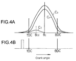
- a lift curve C1 for opening the intake valve V I1 by the first intake-side opening and closing cam 23 is shown and establishes that its opening angle center time ⁇ c of the maximum opening lift is a center time between the intake top dead center TDC and the intake bottom dead center BDC of the piston 4 and crankshaft.
- An opening and closing timing for the intake valve V I2 that is only slightly opened by the slight-operating cam 25 is set such that an opening angle center time ⁇ c2 in a slight lift curve C2 provided by the slight-operating cam 25, i.e., the time at which the lift amount of the intake valve V I2 is maximized, is provided in the first half of the intake stroke.
- the C2 represents the lift caused by the shape of cam 25, which shape is not shown in the Figures because it would hardly be distinguishable from a perfect circle because of the small amount of lift over a substantial circumferential distance for the cam lobe.
- the connecting piston 36 is urged to move in a direction to increase the volume of the hydraulic pressure chamber 40 against a spring force of the return spring 39, while urging the connecting pin 37.
- the connecting piston 36, the connecting pin 37 and the limiting member 38 have been aligned with one another, i.e., when each of the intake-side rocker arms 18, 19 and 20 has reached its stationary state because they engage base circle portions of their respective cams, the connecting piston 36 is fitted into the second intake-side rocker arm 19.
- the connecting pin 37 is fitted into the third intake-side rocker arm 20, thereby achieving the connected states of the intake-side rocker arms 18, 19 and 20. Consequently, the first and third intake-side rocker arms 18 and 20 are swung along with the second intake-side rocker arm 19 that is swung by the second intake-side opening and closing cam 24, which has a larger lift than cams 23 and 25, thereby causing the intake valves V I1 and V I2 to be opened and closed as shown by an opening lift curve C3 with a timing and a lift amount according to the profile of the second intake-side opening and closing cam 24. At all times, the exhaust-side rocker arms 21, 21 cause the exhaust V E1 and V E2 to be opened and closed with a timing and a lift amount according to the profiles of the exhaust-side opening and closing cam 26, 26.
- a spark plug sleeve 44 is provided in the cylinder head 2 between the two exhaust-side rocker arms 21, 21, such that it is inclined toward the exhaust side of the engine.
- a spark plug 45 is inserted through the plug sleeve 44 and mounted to the cylinder head 2 substantially at a central portion of the ceiling surface of the combustion chamber 5.
- an air cleaner 49 is connected to the intake port 8 in the cylinder head 2 through an intake manifold 46 and a throttle body 48 having a throttle valve 47.
- An intake passage 50 is defined in the throttle body 48 and the intake manifold 46 between the air cleaner 49 and the intake port 8.
- a bypass passage 51 and a first idle passage 52 are connected in parallel to the intake passage 50 to bypass the throttle valve 47.
- a bypass solenoid control valve 53 is provided in the bypass passage 51, and a wax-operated valve 54 is provided in the first idle passage 52 that is operated in accordance with the temperature of the cooling water in the engine body.
- a fuel injection valve 55 is mounted at the end of the intake manifold 46 adjacent the cylinder head 2 for uniformly injecting a fuel through the intake port 8 toward the intake valve bores 61 and 62.
- a fuel supply source 56 (see Fig. 1) is connected to the fuel injection valve 55.
- a mounting member 58 is mounted at the end of the intake manifold 46 adjacent the cylinder head 2 and includes a mounting hole 57 having an axis extending obliquely from above toward the intake port 8. The fuel injection valve 55 is mounted to the mounting member 58 by pushing the tip end portion thereof into the mounting hole 57.
- the mounting hole 57 includes a small-diameter hole portion 57a, a medium-diameter hole portion 57b and a large-diameter hole portion 57c which are coaxially connected in the order named from the inner side.
- the fuel injection valve 55 has a housing 59 which includes a basically cylindrical valve housing 61 secured at its rear end to a drive housing 60 containing a solenoid drive which is not shown.
- the housing 59 is mounted to the mounting member 58 by pushing the valve housing 60 into the mounting hole 57 with a seal member 62 interposed between the drive housing 60 and the mounting hole 57 at a step between the medium-diameter hole portion 57b and the large-diameter hole portion 57c of the mounting hole 57.
- a cap 63 is fitted into the small-diameter hole portion 57a of the mounting hole 57 with a seal member 64 interposed therebetween, and has, at its rear end, an engage collar 63a engaging a step between the small-diameter hole portion 57a and the medium-diameter hole portion 57b of the mounting hole 57.
- the following holes are provided in a central portion of the cap 63 in the order named from the forward side (the left side in Fig. 5): a pair of fuel injection holes 651 and 652 inclined away from each other in a forward direction, a through-hole 66 commonly leading to rear ends of the fuel injection holes 651 and 652, and a fitting hole 67 having a diameter larger than that of the through-hole 66.
- the tip end of the valve housing 61 in the fuel injection valve 55 is fitted into the fitting hole 67 so that it is received in the step between the through-hole 66 and the fitting hole 67.
- a valve bore 68 and a tapered valve seat 69 connected to the valve bore 68 are coaxially provided at a central portion of the tip end of the valve housing 61.
- a valve member 70 is axially movably accommodated in the valve housing 61 and is seatable on the valve seat 69.
- the valve member 70 is driven axially by the solenoid drive contained in the drive housing 60 between a position in which it is seated on the valve seat 69 to close the valve bore 68 and a position in which it is moved away from the valve seat 69 to open the valve bore 68.
- the fuel from the fuel supply source 56 is injected through the pair of fuel injection holes 651 and 652 via the valve bore 68 and the through-hole 66.
- the fuel injection valve 55 is mounted to the mounting member 58, so that the fuel from the fuel injection holes 651 and 652 is injected equally into the intake valve bores 61 and 62 opened and closed by the intake valves V I1 and V I2 , as shown in Fig. 6.
- a communication hole 86 may be provided in a diverging wall 85 far partitioning the intake valve bores 61 and 62, as shown in Figs. 2 and 6.
- This communication hole 86 may be formed to smoothly guide the intake air flow from toward the intake valve bore 62 opened by the intake valve V I2 when operated in only a small lift amount toward the intake valve bore 61.
- the fuel deposited on the side of the diverging wall 85 adjacent the intake valve bore 62 can be guided along with a portion of the intake air flow toward the intake valve bore 61, thereby enabling the formation of a homogenous air mixture and an providing an improvement in swirl characteristic to contribute to a reduction in the amount of harmful exhaust gas.
- an annular air chamber 71 is defined between an inner surface of the mounting member 58 and the housing 59, and a passage 72 is provided in the mounting member 58 to lead to the air chamber 71.
- a pair of air assist holes 731 and 732 are provided in the cap 63 and have rear ends commonly communicating with the air chamber 71. The front ends of the air assist holes 731 and 732 are opened into rear ends of the fuel injection holes 651 and 652.
- the passage 72 in mounting member 58 for each cylinder is connected to an air header 74.
- the air header 74 is connected to the intake passage 50 upstream of the throttle valve 47.
- the pair of air assist holes 731 and 732, the air chamber 71, the air header 74, a solenoid type air amount control valve 75 and an idle adjusting screw 76 constitute an assist air supply means 77.
- An exhaust manifold 79 defining an exhaust passage 78 is connected to catalytic converter and a silencer, which are not shown, and is connected to the exhaust port 9 in the cylinder head 2.
- An exhaust gas return line 80 is provided to connect a portion of the exhaust passage 78 and a portion of the intake passage 50 downstream from the throttle valve 47.
- An exhaust gas control valve 81 is provided in the middle of the exhaust gas return line 80, and a solenoid type pilot valve 82 is provided between the exhaust gas control valve 81 and the portion of the intake passage 50 downstream from the throttle valve 47.
- connection switching solenoid control valve 42 The operations of the connection switching solenoid control valve 42, the bypass solenoid control valve 53, the fuel injection valve 55, the solenoid type air amount control valve 75 in the assist air supply means and the solenoid type pilot valve 82 are controlled by a control means 84 including a computer.
- Supplied to the control means 84 are the intake pressure detected by an intake pressure sensor S P , the temperature of the cooling water detected by an engine cooling water temperature sensor S T , the number of revolutions of the engine detected by a revolution-number sensor S N , the detection value detected by an air-fuel ratio sensor S A for detecting an air-fuel ratio from the exhaust gas composition in the exhaust passage 78, the opening degree of the throttle valve 57 detected by a throttle sensor S V , the opening degree of the exhaust gas control valve 81 detected by a lift sensor S L , i.e., an in indication of the amount of exhaust gas returned, and the like.
- the control means 84 controls the operation of the valve characteristic varying means 35 in the valve operating device 16 in order to substantially stop the suction of air through the intake valve bore 62 by substantially stopping the operation of intake valve V I2 of the intake valves V I1 and V I2 to produce a swirl in the combustion chamber 5 during low loading of the engine, and controls the operation of the valve characteristic varying means 35 in the valve operating device 16 to operate both of the intake valves V I1 and V I2 during high loading of the engine, while at the same time, controlling the operations of the solenoid type air amount control valve 75 and the solenoid type pilot valve 82 in order to control the supply of the assist air from the assist air supply means 77 as well as the amount of exhaust gas returned in accordance with the operating condition of the engine.
- the control means 84 also controls the timing of the injection of the fuel from the fuel injection valve 55, so that the injection of the fuel is completed prior to the intake top dead center TDC, as shown in Fig. 4B when one V I2 of the intake valves V I1 and V I2 is in its substantially stopped state.
- the control means 84 causes the intake-side rocker arms 18, 19 and 20 to be connected to one another by the valve operating-characteristic varying means 35, and the valve operating device 16 opens and closes the intake valves V I1 and V I2 with a timing and a lift amount which are determined by the second intake-side opening and closing cam 24.
- the valve operating-characteristic varying means 35 When the engine is in a low-speed and low-load state, the valve operating-characteristic varying means 35 is switched to a state in which it disconnects the intake-side rocker arms 18, 19 and 20. This causes only one intake valve V I1 of the intake valves V I1 and V I2 to be opened and closed with a timing and a lift amount which are determined by the first intake-side opening and closing cam 23, while allowing the other intake valve V I2 to be substantially stopped. In this case, the other intake valve V I2 is brought into a substantially stopped state in which it will be slightly opened, rather into a completely stopped or closed state. This makes it possible to prevent the fuel injected from the fuel injection valve 55 from accumulating between the intake valve bore 62 and the intake port 8 to avoid a variation in the air-fuel ratio.
- the air-fuel mixture is permitted to flow into the combustion chamber 5 substantially through only one intake valve bore 61 of the intake valve bores 61 and 62 to produce a swirl in the combustion chamber 5.
- the timing of opening and closing of the intake valve V I2 is set at a time point such that the lift amount is maximized in a first half of the intake stroke of the piston 4.
- the atomization of the fuel supplied through the intake valve bore 61 into the combustion chamber 5 can be promoted by a relatively high flow speed of the intake air with the opening and closing of the intake valve V I2 in the small lift amount, thereby enhancing the combustibility of the fuel in the combustion chamber 5.
- the curve A shown by a solid line indicates the results provided when the timing of the opening and closing of the intake valve V I2 in the small amount is set in the first half of the intake stroke
- the curve B shown by a dashed line indicates the results provided when the timing of the opening and closing of the intake valve V I2 is set in the second half.
- the timing of the injection of the fuel from the fuel injection valve 55 is set at a time point such that the injection of the fuel is completed prior to the intake top dead center TDC. Therefore, at the time the intake valve V I2 is opened in the first half of the intake stroke, the injection of the fuel from the fuel injection valve 55 has been completed, so that the fuel injected from the fuel injection valve 55 can be reliably introduced at a high intake air flow speed into the combustion chamber 5, which contributes to an improvement in responsiveness of the control of the air-fuel ratio.
- the fuel injection valve 55 includes the assist air supply means 77 and hence, in addition to the atomization of the fuel by the high air flow speed, the atomization of the fuel also can be provided by the air assist to further enhance the combustibility.
- the fuel injection valve 55 since the fuel injection valve 55 includes the pair of fuel injection holes 651 and 652, the amount of fuel injected toward the intake valve bores 61 and 62 by the fuel injection holes 651 and 652 can be equalized substantially reliably.
- the responsiveness of the control of the air-fuel ratio can be further improved, leading to an enhancement in the accuracy of the control of the air-fuel ratio to an optimal value for purification of the exhaust gas by a catalyst, and providing an enhancement in the nature of the exhaust gas and an increase in power output from the engine.
- the fuel injection valve 55 includes the pair of fuel injection holes 651 and 652 for injecting the fuel equally toward the intake valve bores 61 and 62, it is possible to supply a required amount of the fuel through the intake valve bores 61 and 62 into the combustion chamber 5 to contribute to an increase in power output from the engine, when the intake valves V I1 and V12 are opened and closed by the second intake-side opening and closing cam 24 during high loading of the engine.
Landscapes
- Engineering & Computer Science (AREA)
- Mechanical Engineering (AREA)
- General Engineering & Computer Science (AREA)
- Chemical & Material Sciences (AREA)
- Combustion & Propulsion (AREA)
- Valve Device For Special Equipments (AREA)
- Output Control And Ontrol Of Special Type Engine (AREA)
- Valve-Gear Or Valve Arrangements (AREA)
- Electrical Control Of Air Or Fuel Supplied To Internal-Combustion Engine (AREA)
Applications Claiming Priority (2)
| Application Number | Priority Date | Filing Date | Title |
|---|---|---|---|
| JP241723/93 | 1993-09-28 | ||
| JP5241723A JP2762216B2 (ja) | 1993-09-28 | 1993-09-28 | 内燃機関 |
Publications (2)
| Publication Number | Publication Date |
|---|---|
| EP0649976A1 true EP0649976A1 (de) | 1995-04-26 |
| EP0649976B1 EP0649976B1 (de) | 1998-03-04 |
Family
ID=17078584
Family Applications (1)
| Application Number | Title | Priority Date | Filing Date |
|---|---|---|---|
| EP94115197A Expired - Lifetime EP0649976B1 (de) | 1993-09-28 | 1994-09-27 | Brennkraftmaschine |
Country Status (4)
| Country | Link |
|---|---|
| US (1) | US5558060A (de) |
| EP (1) | EP0649976B1 (de) |
| JP (1) | JP2762216B2 (de) |
| DE (1) | DE69408774T2 (de) |
Cited By (3)
| Publication number | Priority date | Publication date | Assignee | Title |
|---|---|---|---|---|
| EP1106792A3 (de) * | 1999-12-06 | 2002-11-27 | Nissan Motor Company, Limited | Steuerapparat für Verbrennungsmotoren |
| EP1291511A3 (de) * | 2001-09-07 | 2006-04-05 | Honda Giken Kogyo Kabushiki Kaisha | Gerät zur Steuerung der Kraftstoffeinspritzung |
| DE10157659B4 (de) * | 2000-12-05 | 2008-06-05 | Ford Global Technologies, LLC (n.d.Ges.d. Staates Delaware), Dearborn | Einlassventil-Zeitsteuerung für nockenlose Mehrventilmotoren |
Families Citing this family (13)
| Publication number | Priority date | Publication date | Assignee | Title |
|---|---|---|---|---|
| US8215292B2 (en) | 1996-07-17 | 2012-07-10 | Bryant Clyde C | Internal combustion engine and working cycle |
| US7281527B1 (en) | 1996-07-17 | 2007-10-16 | Bryant Clyde C | Internal combustion engine and working cycle |
| US7222614B2 (en) | 1996-07-17 | 2007-05-29 | Bryant Clyde C | Internal combustion engine and working cycle |
| US5924396A (en) * | 1996-10-07 | 1999-07-20 | Yamaha Hatsudoki Kabushiki Kaisha | Engine valve actuating system |
| JP3366196B2 (ja) * | 1996-11-19 | 2003-01-14 | 本田技研工業株式会社 | 内燃機関の動弁装置 |
| US7178492B2 (en) | 2002-05-14 | 2007-02-20 | Caterpillar Inc | Air and fuel supply system for combustion engine |
| US6688280B2 (en) | 2002-05-14 | 2004-02-10 | Caterpillar Inc | Air and fuel supply system for combustion engine |
| US7201121B2 (en) | 2002-02-04 | 2007-04-10 | Caterpillar Inc | Combustion engine including fluidically-driven engine valve actuator |
| US7191743B2 (en) | 2002-05-14 | 2007-03-20 | Caterpillar Inc | Air and fuel supply system for a combustion engine |
| US7252054B2 (en) | 2002-05-14 | 2007-08-07 | Caterpillar Inc | Combustion engine including cam phase-shifting |
| US7565899B2 (en) * | 2007-06-12 | 2009-07-28 | Ford Global Technologies, Llc | Engine fueling control during cylinder valve mode transitions |
| US7715974B2 (en) | 2007-10-09 | 2010-05-11 | Ford Global Technologies, Llc | Method for controlling air-fuel ratio for an alternating valve engine |
| JP5758253B2 (ja) * | 2011-09-25 | 2015-08-05 | 本田技研工業株式会社 | 多気筒内燃機関 |
Citations (6)
| Publication number | Priority date | Publication date | Assignee | Title |
|---|---|---|---|---|
| DE3515044A1 (de) * | 1984-04-27 | 1985-11-07 | Mazda Motor Corp., Hiroshima | Brennstoff-einspritzsystem fuer eine brennkraftmaschine |
| DE4103918A1 (de) * | 1990-02-15 | 1991-08-22 | Aisan Ind | Mehrloch-einspritzdueseneinrichtung |
| EP0470869A1 (de) * | 1990-08-10 | 1992-02-12 | Honda Giken Kogyo Kabushiki Kaisha | Brennkraftmaschine |
| US5172674A (en) * | 1990-11-30 | 1992-12-22 | Honda Giken Kogyo Kabushiki Kaisha | Internal combustion engine |
| GB2257204A (en) * | 1991-07-01 | 1993-01-06 | Nissan Motor | I.c. engine valve gear. |
| EP0607992A1 (de) * | 1993-01-22 | 1994-07-27 | Honda Giken Kogyo Kabushiki Kaisha | Einlassvorrichtung für Brennkraftmaschine |
Family Cites Families (3)
| Publication number | Priority date | Publication date | Assignee | Title |
|---|---|---|---|---|
| US4667636A (en) * | 1985-03-22 | 1987-05-26 | Toyota Jidosha Kabushiki Kaisha | Fuel injection type internal combustion engine |
| US4759321A (en) * | 1985-06-24 | 1988-07-26 | Nissan Motor Co., Ltd. | Valve timing arrangement for internal combustion engine having multiple inlet valves per cylinder |
| JPH03279623A (ja) * | 1990-03-27 | 1991-12-10 | Mazda Motor Corp | 多弁式エンジンの制御装置 |
-
1993
- 1993-09-28 JP JP5241723A patent/JP2762216B2/ja not_active Expired - Fee Related
-
1994
- 1994-09-27 DE DE69408774T patent/DE69408774T2/de not_active Expired - Fee Related
- 1994-09-27 EP EP94115197A patent/EP0649976B1/de not_active Expired - Lifetime
- 1994-09-28 US US08/314,429 patent/US5558060A/en not_active Expired - Lifetime
Patent Citations (6)
| Publication number | Priority date | Publication date | Assignee | Title |
|---|---|---|---|---|
| DE3515044A1 (de) * | 1984-04-27 | 1985-11-07 | Mazda Motor Corp., Hiroshima | Brennstoff-einspritzsystem fuer eine brennkraftmaschine |
| DE4103918A1 (de) * | 1990-02-15 | 1991-08-22 | Aisan Ind | Mehrloch-einspritzdueseneinrichtung |
| EP0470869A1 (de) * | 1990-08-10 | 1992-02-12 | Honda Giken Kogyo Kabushiki Kaisha | Brennkraftmaschine |
| US5172674A (en) * | 1990-11-30 | 1992-12-22 | Honda Giken Kogyo Kabushiki Kaisha | Internal combustion engine |
| GB2257204A (en) * | 1991-07-01 | 1993-01-06 | Nissan Motor | I.c. engine valve gear. |
| EP0607992A1 (de) * | 1993-01-22 | 1994-07-27 | Honda Giken Kogyo Kabushiki Kaisha | Einlassvorrichtung für Brennkraftmaschine |
Cited By (3)
| Publication number | Priority date | Publication date | Assignee | Title |
|---|---|---|---|---|
| EP1106792A3 (de) * | 1999-12-06 | 2002-11-27 | Nissan Motor Company, Limited | Steuerapparat für Verbrennungsmotoren |
| DE10157659B4 (de) * | 2000-12-05 | 2008-06-05 | Ford Global Technologies, LLC (n.d.Ges.d. Staates Delaware), Dearborn | Einlassventil-Zeitsteuerung für nockenlose Mehrventilmotoren |
| EP1291511A3 (de) * | 2001-09-07 | 2006-04-05 | Honda Giken Kogyo Kabushiki Kaisha | Gerät zur Steuerung der Kraftstoffeinspritzung |
Also Published As
| Publication number | Publication date |
|---|---|
| JPH0797971A (ja) | 1995-04-11 |
| EP0649976B1 (de) | 1998-03-04 |
| US5558060A (en) | 1996-09-24 |
| DE69408774D1 (de) | 1998-04-09 |
| JP2762216B2 (ja) | 1998-06-04 |
| DE69408774T2 (de) | 1998-07-02 |
Similar Documents
| Publication | Publication Date | Title |
|---|---|---|
| US5558060A (en) | Internal combustion engine | |
| US5209201A (en) | Internal combustion engine | |
| CA1274132A (en) | Valve operating mechanism for internal combustion engine | |
| US5592907A (en) | Valve operating system for multi-cylinder internal combustion engine | |
| US4182289A (en) | Variable valve timing system for internal combustion engine | |
| US5095859A (en) | Sohc type internal combustion engine | |
| US5463995A (en) | Intake system for internal combustion engine | |
| US5799638A (en) | Direction injection system for multi-valve engine | |
| US5220899A (en) | Internal combustion engine with air assist fuel injection control system | |
| JPH0893515A (ja) | 内燃機関における動弁特性および空燃比の切換制御方法 | |
| US5172674A (en) | Internal combustion engine | |
| US5121716A (en) | Fuel injection type internal combustion engine | |
| US6892696B2 (en) | Internal combustion engine | |
| EP0997611B1 (de) | Brennkraftmaschine mit Direkteinspritzung | |
| JPH0494407A (ja) | 内燃機関 | |
| JPH0830433B2 (ja) | 内燃機関 | |
| JP3127317B2 (ja) | 多気筒内燃機関の排ガス還流装置 | |
| JPH02221612A (ja) | 内燃機関の可変動弁装置 | |
| KR100387867B1 (ko) | 엔진의 가변 밸브 리프트 장치 | |
| WO2020229860A1 (ja) | 内燃機関 | |
| JPH06173625A (ja) | エンジンの弁作動装置 | |
| JPH0733762B2 (ja) | 内燃機関のバルブ作動制御装置 | |
| JPH0742408U (ja) | 多弁エンジンの吸気装置 |
Legal Events
| Date | Code | Title | Description |
|---|---|---|---|
| PUAI | Public reference made under article 153(3) epc to a published international application that has entered the european phase |
Free format text: ORIGINAL CODE: 0009012 |
|
| AK | Designated contracting states |
Kind code of ref document: A1 Designated state(s): DE GB |
|
| 17P | Request for examination filed |
Effective date: 19951020 |
|
| 17Q | First examination report despatched |
Effective date: 19970129 |
|
| GRAG | Despatch of communication of intention to grant |
Free format text: ORIGINAL CODE: EPIDOS AGRA |
|
| GRAG | Despatch of communication of intention to grant |
Free format text: ORIGINAL CODE: EPIDOS AGRA |
|
| GRAH | Despatch of communication of intention to grant a patent |
Free format text: ORIGINAL CODE: EPIDOS IGRA |
|
| GRAH | Despatch of communication of intention to grant a patent |
Free format text: ORIGINAL CODE: EPIDOS IGRA |
|
| GRAA | (expected) grant |
Free format text: ORIGINAL CODE: 0009210 |
|
| AK | Designated contracting states |
Kind code of ref document: B1 Designated state(s): DE GB |
|
| REF | Corresponds to: |
Ref document number: 69408774 Country of ref document: DE Date of ref document: 19980409 |
|
| PLBE | No opposition filed within time limit |
Free format text: ORIGINAL CODE: 0009261 |
|
| STAA | Information on the status of an ep patent application or granted ep patent |
Free format text: STATUS: NO OPPOSITION FILED WITHIN TIME LIMIT |
|
| 26N | No opposition filed | ||
| REG | Reference to a national code |
Ref country code: GB Ref legal event code: IF02 |
|
| PGFP | Annual fee paid to national office [announced via postgrant information from national office to epo] |
Ref country code: DE Payment date: 20070920 Year of fee payment: 14 |
|
| PGFP | Annual fee paid to national office [announced via postgrant information from national office to epo] |
Ref country code: GB Payment date: 20070926 Year of fee payment: 14 |
|
| GBPC | Gb: european patent ceased through non-payment of renewal fee |
Effective date: 20080927 |
|
| PG25 | Lapsed in a contracting state [announced via postgrant information from national office to epo] |
Ref country code: DE Free format text: LAPSE BECAUSE OF NON-PAYMENT OF DUE FEES Effective date: 20090401 |
|
| PG25 | Lapsed in a contracting state [announced via postgrant information from national office to epo] |
Ref country code: GB Free format text: LAPSE BECAUSE OF NON-PAYMENT OF DUE FEES Effective date: 20080927 |