EP0649983B1 - Soupape à commande électromagnétique de dosage et de pulvérisation de carburant - Google Patents
Soupape à commande électromagnétique de dosage et de pulvérisation de carburant Download PDFInfo
- Publication number
- EP0649983B1 EP0649983B1 EP94116845A EP94116845A EP0649983B1 EP 0649983 B1 EP0649983 B1 EP 0649983B1 EP 94116845 A EP94116845 A EP 94116845A EP 94116845 A EP94116845 A EP 94116845A EP 0649983 B1 EP0649983 B1 EP 0649983B1
- Authority
- EP
- European Patent Office
- Prior art keywords
- former
- valve
- casing
- annular
- lower portion
- Prior art date
- Legal status (The legal status is an assumption and is not a legal conclusion. Google has not performed a legal analysis and makes no representation as to the accuracy of the status listed.)
- Expired - Lifetime
Links
- 239000000446 fuel Substances 0.000 title claims description 17
- 238000004804 winding Methods 0.000 claims description 9
- 230000005291 magnetic effect Effects 0.000 claims description 7
- 238000002347 injection Methods 0.000 claims description 6
- 239000007924 injection Substances 0.000 claims description 6
- 238000002485 combustion reaction Methods 0.000 claims description 4
- 239000003302 ferromagnetic material Substances 0.000 claims description 3
- 210000002105 tongue Anatomy 0.000 description 7
- 238000004519 manufacturing process Methods 0.000 description 1
- 239000000463 material Substances 0.000 description 1
- 239000004033 plastic Substances 0.000 description 1
- 229920003023 plastic Polymers 0.000 description 1
Images

Classifications
-
- F—MECHANICAL ENGINEERING; LIGHTING; HEATING; WEAPONS; BLASTING
- F02—COMBUSTION ENGINES; HOT-GAS OR COMBUSTION-PRODUCT ENGINE PLANTS
- F02M—SUPPLYING COMBUSTION ENGINES IN GENERAL WITH COMBUSTIBLE MIXTURES OR CONSTITUENTS THEREOF
- F02M61/00—Fuel-injectors not provided for in groups F02M39/00 - F02M57/00 or F02M67/00
- F02M61/16—Details not provided for in, or of interest apart from, the apparatus of groups F02M61/02 - F02M61/14
- F02M61/168—Assembling; Disassembling; Manufacturing; Adjusting
-
- F—MECHANICAL ENGINEERING; LIGHTING; HEATING; WEAPONS; BLASTING
- F02—COMBUSTION ENGINES; HOT-GAS OR COMBUSTION-PRODUCT ENGINE PLANTS
- F02M—SUPPLYING COMBUSTION ENGINES IN GENERAL WITH COMBUSTIBLE MIXTURES OR CONSTITUENTS THEREOF
- F02M51/00—Fuel-injection apparatus characterised by being operated electrically
- F02M51/06—Injectors peculiar thereto with means directly operating the valve needle
- F02M51/061—Injectors peculiar thereto with means directly operating the valve needle using electromagnetic operating means
- F02M51/0625—Injectors peculiar thereto with means directly operating the valve needle using electromagnetic operating means characterised by arrangement of mobile armatures
- F02M51/0664—Injectors peculiar thereto with means directly operating the valve needle using electromagnetic operating means characterised by arrangement of mobile armatures having a cylindrically or partly cylindrically shaped armature, e.g. entering the winding; having a plate-shaped or undulated armature entering the winding
- F02M51/0667—Injectors peculiar thereto with means directly operating the valve needle using electromagnetic operating means characterised by arrangement of mobile armatures having a cylindrically or partly cylindrically shaped armature, e.g. entering the winding; having a plate-shaped or undulated armature entering the winding the armature acting as a valve or having a short valve body attached thereto
Definitions
- the present invention relates to an electromagnetically actuated fuel metering and atomising valve, intended to be fitted to the fuel supply device of an internal combustion engine.
- valves of the above type include a main body internally housing an annular electromagnet, a core and a movable valve shutter element.
- the electromagnet consists of a support former and an electrical winding.
- a main disadvantage lies in the fact that the former and the main body are not directly fixed to each other, but are fixed indirectly by connection between the various fixed components of the valve. It is clear that clearances may exist between the former and the main body, which clearances could increase over time making the position of the electrical winding unstable relative to the axial air gap of the magnetic circuit defined in the valve. It is clear that this instability affects the axial component of the magnetic force controlling the stroke of the valve shutter element, meaning that for each similar command to the electromagnet the time taken for the valve shutter member to complete its stroke could be different. In addition, this clearance could compromise the fluid-tight seal of the valve as the seals would age prematurely as a result of the extra stress (vibration of the various elements) to which they were subjected.
- the object of the present invention is to provide an electromagnetically operated fuel metering and atomising valve free from the above disadvantages, that is to say one provided with a system which prevents clearances from forming and at the same time provides a reliable fluid-tight seal.
- An electromagnetically actuated fuel metering and atomising valve intended to be fitted in a fuel supply system of an internal combustion engine, comprising:
- a magnetically actuated fuel metering and atomising valve is intended to be fitted in the fuel supply device of an internal combustion engine.
- the valve 1 comprises:
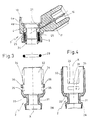
- the former 4 is constituted by two tubular parts 4a and 4b, securely fixed one within the other and made of plastics material, defining within them the seat for the winding 5.
- a body 17 extends obliquely upwards from an upper area of the outermost section 4b and constitutes an electrical connector as it houses blade-like pins 18 through which the winding 5 is supplied.
- a wall 19 extends upwardly from an upper area of the section 4b, in a position diametrically opposite the body 17.
- An annular recess 21 is formed in the inner surface of the upper end of the inner part 4a of the former 4 to house an annular seal 22 which is compressed radially by the portion 7 of the body 6.
- the seat for the seal 22 is closed at the top by an annular shoulder 23 formed in the body 6.
- the part 4a of the former 4 has an annular base wall from which an annular pressure foot 24 extends downwardly.
- two small part-annular grooves 25 are formed in the outer surface of the part 4b.
- one groove 25 is formed just beneath the lower end of the wall 19 and the other groove 25 is formed just beneath the lower end of the body 17.
- the portion 7 of the body 6 is installed within the former 4 and contains an annular pin 26 the function of which is to engage against a coil spring 27 arranged fitted betwen the pin 26 and the valve shutter member 8 which is defined by a small plate.
- the body 2 comprises:
- the former 4 is housed in the portion 32, and the annular base wall of the part 4a of the former 4 and the wall 33 define between them an annular seat in which is fitted an annular seal 29 which is compressed axially by the part 4a.
- the seat for the seal 29 is closed on the inside by the annular foot 24.
- the seal 29 is first placed on the wall 33 then the former 4 is fitted into the portion 32 of the body 2, taking care to orientate the former 4 in such a way that the wall 19 and the body 17 are in correspondence with a respective notch 34.
- the former 4 is then pressed against the wall 33 so as to compress the seal 29 in such a way that the tongues 36 are moved into correspondence with respective grooves 25.
- the invention provides a valve which is simple to manufacture and easy to assemble; it can be assembled with the use of automated machinery.
- the main advantage of the valve according to the present invention lies in having provided axial interlock between the valve casing and the electromagnet. This interlock enables the position of the electrical winding to be kept stable relative to the wall 33 and thus relative to the airgap of the magnetic circuit, this airgap being defined between the portion 7 of the body 6 and the armature 2.
- the seal 29 in addition to its role in providing an axial, and therefore particularly effective, fluid-tight seal, the seal 29 also acts as an axial spring, maintaining constant the pressure of the bottom of the grooves 25 against the lower edge of the tongues 36.
- the locking system between the casing and the electromagnet enables the size of the valve 1 to be kept compact.
- interlocking system between the casing and the electromagnet may also be applied to valves which provide for the fuel to enter a central area.
- this locking system may be made differently from the way described above.
Landscapes
- Engineering & Computer Science (AREA)
- Chemical & Material Sciences (AREA)
- Combustion & Propulsion (AREA)
- Mechanical Engineering (AREA)
- General Engineering & Computer Science (AREA)
- Physics & Mathematics (AREA)
- Electromagnetism (AREA)
- Manufacturing & Machinery (AREA)
- Fuel-Injection Apparatus (AREA)
- Magnetically Actuated Valves (AREA)
Claims (5)
- Soupape à commande électromagnétique de dosage et d'atomisation de carburant, destinée à être montée dans un système d'alimentation en carburant d'un moteur à combustion interne, comprenant :caractérisée en ce qu'elle comprend un système de verrouillage axial entre ledit boítier (2) et ledit support (4), ce système de verrouillage comportant au moins une languette (36) formée sur ledit boítier (2) et s'engageant dans une rainure (25) formée dans ledit support (4).un boítier tubulaire (2) logeant la partie inférieure de ladite soupape;un électroaimant (3) défini par un support tubulaire (4) et un bobinage électrique (5) disposé dans un siège annulaire formé à l'intérieur dudit support (4);un corps tubulaire (6) pourvu d'une partie inférieure (7) formée d'un matériau ferromagnétique constituant le noyau d'un circuit magnétique défini dans ladite soupape;un élément mobile formant obturateur (8) de la soupape, pouvant être actionné pour commander l'écoulement du carburant dans un orifice d'injection (11);une armature tubulaire mobile (12) attirée par ladite partie inférieure (7) dudit corps (6) lorsque l'électroaimant (3) est excité et supportant ledit élément formant obturateur (8) de la soupape;une plaque (13) dans laquelle est formé ledit orifice d'injection (11); etune entrée (14) pour le carburant, définie dans ledit corps (6);
- Soupape selon la revendication 1, caractérisée en ce que l'engagement de ladite languette (36) dans ladite rainure (25) est défini par une déformation de la languette (36).
- Soupape selon la revendication 2, caractérisée en ce que ledit boítier (2) comprend :une partie inférieure (28) logeant ladite plaque (13);une partie centrale (31) possédant un diamètre intérieur inférieur à celui de ladite partie inférieure (28), dans laquelle ladite armature (12) et ledit élément obturateur (8) de la soupape peuvent glisser; etune partie supérieure (32) possédant un diamètre intérieur supérieur à celui de ladite partie centrale (31) de manière à définir une paroi annulaire (33) entre ces deux éléments; le support (4) étant logé dans ladite partie supérieure (32).
- Soupape selon la revendication 3, caractérisée en ce qu'un siège annulaire est défini entre une paroi de base annulaire dudit support et la paroi annulaire (33) dudit boítier (2), et loge un joint d'étanchéité annulaire (29), qui est comprimé axialement par ledit support (4).
- Soupape selon la revendication 4, caractérisée en ce que deux rainures partiellement annulaires (25) sont formées dans ledit support (4) dans des positions diamétralement opposées et que deux encoches diamétralement opposées (34) sont formées dans ladite partie supérieure (32) dudit boítier (2), avec leurs axes longitudinaux parallèles à un axe longitudinal (X) dudit boítier (2), et que dans le fond de chaque encoche (34) une fente est formée à travers ladite partie supérieure (32) qui définit, avec le fond d'une encoche respective (34), ladite languette (36).
Applications Claiming Priority (2)
| Application Number | Priority Date | Filing Date | Title |
|---|---|---|---|
| IT93BO000424A IT1264720B1 (it) | 1993-10-26 | 1993-10-26 | Valvola dosatrice e polverizzatrice di carburante ad azionamento elettromagnetico. |
| ITBO930424 | 1993-10-26 |
Publications (2)
| Publication Number | Publication Date |
|---|---|
| EP0649983A1 EP0649983A1 (fr) | 1995-04-26 |
| EP0649983B1 true EP0649983B1 (fr) | 1998-01-21 |
Family
ID=11339281
Family Applications (1)
| Application Number | Title | Priority Date | Filing Date |
|---|---|---|---|
| EP94116845A Expired - Lifetime EP0649983B1 (fr) | 1993-10-26 | 1994-10-25 | Soupape à commande électromagnétique de dosage et de pulvérisation de carburant |
Country Status (4)
| Country | Link |
|---|---|
| EP (1) | EP0649983B1 (fr) |
| DE (1) | DE69408084T2 (fr) |
| ES (1) | ES2113029T3 (fr) |
| IT (1) | IT1264720B1 (fr) |
Families Citing this family (8)
| Publication number | Priority date | Publication date | Assignee | Title |
|---|---|---|---|---|
| DE19631280A1 (de) * | 1996-08-02 | 1998-02-05 | Bosch Gmbh Robert | Brennstoffeinspritzventil und Verfahren zur Herstellung |
| DE19640782A1 (de) * | 1996-10-02 | 1998-04-09 | Bosch Gmbh Robert | Ventil und Verfahren zur Herstellung eines Ventiles |
| DE19712591A1 (de) * | 1997-03-26 | 1998-10-01 | Bosch Gmbh Robert | Brennstoffeinspritzventil und Verfahren zur Herstellung sowie Verwendung eines Brennstoffeinspritzventils |
| US6019297A (en) * | 1998-02-05 | 2000-02-01 | Siemens Automotive Corporation | Non-magnetic shell for welded fuel injector |
| DE19860631A1 (de) * | 1998-12-29 | 2000-07-06 | Bosch Gmbh Robert | Elektromagnetisch betätigbares Ventil und Verfahren zur Herstellung eines Magnetmantels für ein Ventil |
| DE19900405A1 (de) * | 1999-01-08 | 2000-07-13 | Bosch Gmbh Robert | Verfahren zur Montage einer Ventilbaugruppe eines Brennstoffeinspritzventils |
| DE10055639A1 (de) * | 2000-11-10 | 2002-05-23 | Siemens Ag | Injektor zum Einspritzen von Kraftstoff in einen Brennraum |
| EP3301293A1 (fr) * | 2016-09-30 | 2018-04-04 | Continental Automotive GmbH | Long injecteur pour moteur à combustion interne |
Family Cites Families (3)
| Publication number | Priority date | Publication date | Assignee | Title |
|---|---|---|---|---|
| GB804116A (en) * | 1955-10-12 | 1958-11-05 | Cav Ltd | Liquid fuel injection nozzles for internal combustion engines |
| JPS59203866A (ja) * | 1983-05-04 | 1984-11-19 | Nippon Denso Co Ltd | 電磁式燃料噴射弁 |
| IT1250846B (it) * | 1991-10-11 | 1995-04-21 | Weber Srl | Valvola dosatrice e polverizzatrice di carburante ad azionamento elettromagnetico avente dimensioni molto ridotte |
-
1993
- 1993-10-26 IT IT93BO000424A patent/IT1264720B1/it active IP Right Grant
-
1994
- 1994-10-25 DE DE69408084T patent/DE69408084T2/de not_active Expired - Lifetime
- 1994-10-25 EP EP94116845A patent/EP0649983B1/fr not_active Expired - Lifetime
- 1994-10-25 ES ES94116845T patent/ES2113029T3/es not_active Expired - Lifetime
Also Published As
| Publication number | Publication date |
|---|---|
| DE69408084T2 (de) | 1998-06-10 |
| IT1264720B1 (it) | 1996-10-04 |
| ES2113029T3 (es) | 1998-04-16 |
| ITBO930424A1 (it) | 1995-04-26 |
| ITBO930424A0 (it) | 1993-10-26 |
| DE69408084D1 (de) | 1998-02-26 |
| EP0649983A1 (fr) | 1995-04-26 |
Similar Documents
| Publication | Publication Date | Title |
|---|---|---|
| US5238224A (en) | Dry coil | |
| US7468647B2 (en) | Linear solenoid having stator core and plunger | |
| US6405427B2 (en) | Method of making a solenoid actuated fuel injector | |
| US6820651B2 (en) | Electrically actuated valve | |
| US6501359B2 (en) | Electromagnetic actuator | |
| US6056264A (en) | Solenoid actuated flow control valve assembly | |
| KR930012230B1 (ko) | 전자조작되는연료분사밸브및그제조법 | |
| EP1229239B1 (fr) | Filtre et ajusteur combinés, pour injecteur de combustible | |
| CN1155920A (zh) | 电磁控制的燃料喷射线圈的壳体 | |
| JP3508832B2 (ja) | ソレノイド弁 | |
| JPS60256552A (ja) | 噴射弁 | |
| US20020007549A1 (en) | Method for manufacturing electromagnetic operating apparatus | |
| KR930012229B1 (ko) | 전자작동식 연료분사밸브 | |
| US6955337B2 (en) | Pneumatic module | |
| EP0678665A1 (fr) | Ensemble d'induit d'un injecteur à combustible | |
| US5174336A (en) | General purpose fluid control valve | |
| GB2333563A (en) | Modular control valve for a fuel injector having magnetic isolation features | |
| EP0649983A1 (fr) | Soupape à commande électromagnétique de dosage et de pulvérisation de carburant | |
| CN1115478C (zh) | 可电磁操纵的阀以及制造用于一个阀的磁壳的方法 | |
| EP0616664B1 (fr) | Etalonnage de l'ecoulement dynamique d'un injecteur de carburant par detournement selectif d'un flux magnetique a partir de l'entrefer | |
| US5465911A (en) | Angled terminal/coil design for small diameter fuel injector | |
| US6962142B2 (en) | Fuel injection system and manufacturing method thereof | |
| US5823445A (en) | Fuel injector with electromagnetically autonomous sub assembly | |
| CN113586744A (zh) | 电磁阀 | |
| JP7656091B2 (ja) | 入口弁組立体を有する燃料ポンプ |
Legal Events
| Date | Code | Title | Description |
|---|---|---|---|
| PUAI | Public reference made under article 153(3) epc to a published international application that has entered the european phase |
Free format text: ORIGINAL CODE: 0009012 |
|
| AK | Designated contracting states |
Kind code of ref document: A1 Designated state(s): DE ES FR GB SE |
|
| RAP1 | Party data changed (applicant data changed or rights of an application transferred) |
Owner name: MAGNETI MARELLI S.P.A. |
|
| 17P | Request for examination filed |
Effective date: 19950512 |
|
| RIN1 | Information on inventor provided before grant (corrected) |
Inventor name: CRISTIANI, MARCELLO Inventor name: VIGNOLI, MIRCO |
|
| 17Q | First examination report despatched |
Effective date: 19960731 |
|
| GRAG | Despatch of communication of intention to grant |
Free format text: ORIGINAL CODE: EPIDOS AGRA |
|
| GRAG | Despatch of communication of intention to grant |
Free format text: ORIGINAL CODE: EPIDOS AGRA |
|
| GRAH | Despatch of communication of intention to grant a patent |
Free format text: ORIGINAL CODE: EPIDOS IGRA |
|
| GRAH | Despatch of communication of intention to grant a patent |
Free format text: ORIGINAL CODE: EPIDOS IGRA |
|
| GRAA | (expected) grant |
Free format text: ORIGINAL CODE: 0009210 |
|
| AK | Designated contracting states |
Kind code of ref document: B1 Designated state(s): DE ES FR GB SE |
|
| REF | Corresponds to: |
Ref document number: 69408084 Country of ref document: DE Date of ref document: 19980226 |
|
| REG | Reference to a national code |
Ref country code: ES Ref legal event code: FG2A Ref document number: 2113029 Country of ref document: ES Kind code of ref document: T3 |
|
| ET | Fr: translation filed | ||
| PLBE | No opposition filed within time limit |
Free format text: ORIGINAL CODE: 0009261 |
|
| STAA | Information on the status of an ep patent application or granted ep patent |
Free format text: STATUS: NO OPPOSITION FILED WITHIN TIME LIMIT |
|
| 26N | No opposition filed | ||
| REG | Reference to a national code |
Ref country code: GB Ref legal event code: IF02 |
|
| PGFP | Annual fee paid to national office [announced via postgrant information from national office to epo] |
Ref country code: SE Payment date: 20090924 Year of fee payment: 16 Ref country code: GB Payment date: 20090928 Year of fee payment: 16 |
|
| PGFP | Annual fee paid to national office [announced via postgrant information from national office to epo] |
Ref country code: ES Payment date: 20091006 Year of fee payment: 16 |
|
| GBPC | Gb: european patent ceased through non-payment of renewal fee |
Effective date: 20101025 |
|
| PG25 | Lapsed in a contracting state [announced via postgrant information from national office to epo] |
Ref country code: GB Free format text: LAPSE BECAUSE OF NON-PAYMENT OF DUE FEES Effective date: 20101025 |
|
| PG25 | Lapsed in a contracting state [announced via postgrant information from national office to epo] |
Ref country code: SE Free format text: LAPSE BECAUSE OF NON-PAYMENT OF DUE FEES Effective date: 20101026 |
|
| REG | Reference to a national code |
Ref country code: ES Ref legal event code: FD2A Effective date: 20111118 |
|
| PG25 | Lapsed in a contracting state [announced via postgrant information from national office to epo] |
Ref country code: ES Free format text: LAPSE BECAUSE OF NON-PAYMENT OF DUE FEES Effective date: 20101026 |
|
| PGFP | Annual fee paid to national office [announced via postgrant information from national office to epo] |
Ref country code: FR Payment date: 20131028 Year of fee payment: 20 Ref country code: DE Payment date: 20130920 Year of fee payment: 20 |
|
| REG | Reference to a national code |
Ref country code: DE Ref legal event code: R071 Ref document number: 69408084 Country of ref document: DE |