EP0650031B1 - Vorrichtung zur Messung einer Fahrzeugbewegung - Google Patents
Vorrichtung zur Messung einer Fahrzeugbewegung Download PDFInfo
- Publication number
- EP0650031B1 EP0650031B1 EP94115498A EP94115498A EP0650031B1 EP 0650031 B1 EP0650031 B1 EP 0650031B1 EP 94115498 A EP94115498 A EP 94115498A EP 94115498 A EP94115498 A EP 94115498A EP 0650031 B1 EP0650031 B1 EP 0650031B1
- Authority
- EP
- European Patent Office
- Prior art keywords
- battery
- rotation
- signal
- rotation signal
- determining
- Prior art date
- Legal status (The legal status is an assumption and is not a legal conclusion. Google has not performed a legal analysis and makes no representation as to the accuracy of the status listed.)
- Expired - Lifetime
Links
- 238000007493 shaping process Methods 0.000 claims description 5
- 238000012544 monitoring process Methods 0.000 claims 1
- 235000014676 Phragmites communis Nutrition 0.000 description 15
- 238000010586 diagram Methods 0.000 description 12
- 238000012545 processing Methods 0.000 description 9
- 230000004044 response Effects 0.000 description 7
- 239000003990 capacitor Substances 0.000 description 5
- 101100057246 Saccharomyces cerevisiae (strain ATCC 204508 / S288c) ENA2 gene Proteins 0.000 description 3
- 238000001514 detection method Methods 0.000 description 3
- 230000005674 electromagnetic induction Effects 0.000 description 3
- 230000006698 induction Effects 0.000 description 3
- 101100057245 Saccharomyces cerevisiae (strain ATCC 204508 / S288c) ENA1 gene Proteins 0.000 description 2
- 239000013078 crystal Substances 0.000 description 2
- 238000013479 data entry Methods 0.000 description 2
- 239000004973 liquid crystal related substance Substances 0.000 description 2
- 238000000034 method Methods 0.000 description 2
- 230000008569 process Effects 0.000 description 2
- 238000012360 testing method Methods 0.000 description 2
- 230000008859 change Effects 0.000 description 1
- 238000004891 communication Methods 0.000 description 1
- 238000012986 modification Methods 0.000 description 1
- 230000004048 modification Effects 0.000 description 1
- 230000001960 triggered effect Effects 0.000 description 1
- 230000000007 visual effect Effects 0.000 description 1
Images



Classifications
-
- G—PHYSICS
- G01—MEASURING; TESTING
- G01C—MEASURING DISTANCES, LEVELS OR BEARINGS; SURVEYING; NAVIGATION; GYROSCOPIC INSTRUMENTS; PHOTOGRAMMETRY OR VIDEOGRAMMETRY
- G01C22/00—Measuring distance traversed on the ground by vehicles, persons, animals or other moving solid bodies, e.g. using odometers, using pedometers
- G01C22/002—Measuring distance traversed on the ground by vehicles, persons, animals or other moving solid bodies, e.g. using odometers, using pedometers for cycles
-
- G—PHYSICS
- G01—MEASURING; TESTING
- G01P—MEASURING LINEAR OR ANGULAR SPEED, ACCELERATION, DECELERATION, OR SHOCK; INDICATING PRESENCE, ABSENCE, OR DIRECTION, OF MOVEMENT
- G01P1/00—Details of instruments
- G01P1/07—Indicating devices, e.g. for remote indication
- G01P1/08—Arrangements of scales, pointers, lamps or acoustic indicators, e.g. in automobile speedometers
- G01P1/10—Arrangements of scales, pointers, lamps or acoustic indicators, e.g. in automobile speedometers for indicating predetermined speeds
-
- G—PHYSICS
- G01—MEASURING; TESTING
- G01P—MEASURING LINEAR OR ANGULAR SPEED, ACCELERATION, DECELERATION, OR SHOCK; INDICATING PRESENCE, ABSENCE, OR DIRECTION, OF MOVEMENT
- G01P3/00—Measuring linear or angular speed; Measuring differences of linear or angular speeds
- G01P3/42—Devices characterised by the use of electric or magnetic means
- G01P3/44—Devices characterised by the use of electric or magnetic means for measuring angular speed
- G01P3/48—Devices characterised by the use of electric or magnetic means for measuring angular speed by measuring frequency of generated current or voltage
- G01P3/481—Devices characterised by the use of electric or magnetic means for measuring angular speed by measuring frequency of generated current or voltage of pulse signals
- G01P3/487—Devices characterised by the use of electric or magnetic means for measuring angular speed by measuring frequency of generated current or voltage of pulse signals delivered by rotating magnets
Definitions
- the present invention relates to apparatus for measuring a running condition of a vehicle by detecting rotation of a wheel of the vehicle.
- Wheeled vehicles running on a road or rails include a bicycle, automobile, electric car or train etc.
- Computer-based running condition measuring apparatus are known which measure or compute a running condition of the vehicle (e.g., vehicle speed, traveled distance). Particularly, when applied to the bicycle, such a running condition measuring apparatus is called "cycle computer.”
- a magnet is mounted on one of spokes of a front wheel while a magnetic detector is fixed to a fork blade to detect passing of the magnet.
- a reed switch has been used as the magnetic detector.
- the reed switch is normally kept in an OFF condition.
- the reed switch When the magnet passes by the reed switch as the wheel rotates, the reed switch is turned ON. Thus it generates a magnet detection signal (reed switch signal) every one revolution of the wheel.
- the number of revolutions of the wheel per unit time is measured from the detection signal.
- the cycle computer CPU computes a traveled distance and/or a speed of the bicycle by multiplying the detected number of revolutions of the wheel by wheel circumference data previously stored.
- a display device such as a liquid crystal display device (LCD) displays the computed results.
- LCD liquid crystal display device
- Some prior art cycle computer employs a transmitter (first device) including a rotation detector, and a receiver (second device) including a CPU for computing the running condition.
- the first and second devices are independently powered by their own battery. When the battery power in the receiver is used up, the transmitter can no longer send a rotation signal to the receiver. In the absence of the rotation signal, the CPU in the receiver mistakes the power failure of the receiver for the stopped condition of the vehicle.
- a wireless velocity detector comprising a mounting device mounted on the hub of a bicycle wheel and a device for displaying velocity.
- Said detector includes a coil that generates a magnetic field when energized. Further, a pair of coils is positioned in a receiver mounted preferably on the handle bar. The receiver sends any variation in the strength of the magnetic field as the field rotates. By this, the receiver is able to display a velocity and a distance travelled.
- Both devices include a power source. For a long battery life and a long power consumption, a signal is only transmitted when the wheel of the bicycle is turning and the receiver turns down power consumption after a predetermined time interval after the last detected signal.
- the first embodiment of the invention is shown in Figs.1-9.
- Fig.1 shows a side elevational view of a bicycle 11 to which the cycle computer of the first embodiment is applied.
- a magnet 14 is attached to one of spokes 13 of a front wheel 12 of the bicycle 11.
- a rotation detector 16 is secured to a fork blade of a body 15 of the bicycle 11.
- the rotation detector 16 is disposed in or by a rotating path of the magnet 14.
- an operation and display device 17 is mounted on a handle 15a.
- the device 17 computes and displays running condition of the bicycle such as traveled distance and/or running speed of the bicycle from the wheel rotation information (rotation signal) detected by the rotation detector 16.
- Radio communication is employed to send the rotation signal from the rotation detector 16 to the operation and display device 17.
- the rotation detector 16, and the operation and display device 17 are independently powered by their own battery.
- Fig.2 shows an external view of the rotation detector 16 and the operation and display device 17 of the cycle computer of Fig.1.
- the rotation detector 16 detects the rotation signal of the front wheel from magnet 14.
- the rotation detector 16 includes a radio transmitter which sends the rotation signal to a radio receiver in the operation and display device 17.
- the operation and display device 17 computes the running condition of the bicycle 11 (e.g., vehicle speed, traveled distance) from the rotation signal, and displays the results on a liquid crystal display device (LCD) 25.
- the operation and display device 17 has a plurality of keys arranged in its periphery, such as data entry key 21 for inputting data (e.g., weight of bicycle and driver) start key 22, end key 23 and second data entry key 24 for entering data (e.g., circumference of the front wheel).
- Figs.3,8 and 9 show a running condition measuring apparatus in accordance with a first embodiment of the invention.
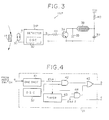
- Fig.3 is a circuit diagram of the rotation detector 16P.
- Fig.8 is a timing chart showing power supplying condition of the rotation detector, and operation and display device together with the rotation signal.
- the rotation detector 16P of the first embodiment generates and transmits the rotation signal (run signal) indicative of the passing of the magnet when the vehicle is running. On the other hand, when the vehicle is stopped, the rotation detector 16P does not generate or transmit any signal to the operation and display device.
- the magnet 14 passes by the reed switch 30, changing the magnetic field.
- the magnetic change turns on the reed switch 30 to output the reed switch signal a to the detector 31P.
- the detector 31P incorporates the oscillator 32.
- the detector circuit 31P converts reed switch signal a into successive clock pulses b .
- the pulses b are applied to the base of N-P-N transistor 34 through the resistor 33.
- the detector circuit 31P is constituted by the one-shot multivibrator 41, oscillator 32 and AND gate 42 shown in Fig.4.
- the capacitor 35 is connected between the collector and emitter of the transistor 34.
- the collector of the transistor 34 is connected to one end of the electromagnetic induction coil 38.
- the emitter is connected to the detector 31P ground.
- a voltage Vcc is applied to the other end of the induction coil 38 and one end of the capacitor 39 through the resistor 40.
- the other end of the capacitor 39 is connected to the emitter of the transistor 34.
- the transistor 34 repeats switching between on and off states in response to the clock pulses b .
- This resonates the LC oscillator (35, 38, 39) so that induction coil 38 emits a radio signal.
- the rotation detector 16P transmits a radio signal (rotation signal) in response to the magnet passing when the vehicle is running. It does not transmit any radio signal, however, when the vehicle is stopped or at rest.
- Fig.4 is a block diagram of the detector 31P shown in Fig.3.
- a one-shot multivibrator 41 In response to the reed switch signal a indicative of the passing of the magnet 14, a one-shot multivibrator 41 generates a one-shot pulse ENA1.
- the one-shot pulse enables an AND gate 42 to pass clock signal pulses from the oscillator 32 during the width of the one-shot pulse.
- a timer 43 is triggered by the one-shot pulse ENA1 to measure lapse of a predetermined time period. If the next one-shot pulse (rotation detection signal) comes in before the timer is timed out, the timer restarts its operation from an initial value. Thus, while the bicycle is running, the timer 43 will not be timed out. When the bicycle is stopped, the reed switch 30 will no longer generate a reed switch signal, causing the timer 43 to time out. Then, the timer 43 generates a stop command signal ENA2 ( e ) for a short time corresponding to the duration of the one-shot pulse.
- the stop command signal ENA2 enables an AND gate 44 to pass clock pulses from the oscillator 32 for the duration of the signal ENA2.
- An NOR gate 45 has two inputs receiving the AND 42 output and AND 44 output, respectively. Thus, the NOR gate 45 outputs clock pulses b either when the magnet 14 passes by the reed switch 30 or when the timer 43 is timed out, indicating the stopped condition of the bicycle 11.
- the rotation detector 16P of the first embodiment transmits a first radio signal (run signal) in response to the passing of the magnet 14 when the bicycle 11 is running.
- the rotation detector 16 transmits a second and different radio signal (stop signal) in response to the time-out of the timer 43.
- the transmitted signal is received by the operation and display device 17.
- Fig.5 shows block diagram of the operation and display device 17 in accordance with the first embodiment.
- a receiver 50 receives the radio signal from the transmitter in the rotation detector 16P.
- the receiver 50 processes the received radio signal into a pulse count.
- the pulse count is supplied to CPU 51.
- CPU 51 is connected to a program ROM (Read Only Memory) 52 and a RAM (Random Access Memory) 53.
- CPU 51 operates in accordance with the program stored in the program ROM to control the entire system of the operation and display device 17, e.g., to control a LCD display 57 through a display driver 56.
- CPU 51 determines from the radio signal pulse count as to whether the vehicle is running or is stopped. Based on the results of determination, CPU 51 selectively stops or re-starts the supplying of electric power from a power supply 58, thus reducing the wasteful consumption of the electric power.
- CPU 51 also uses the results of the determination to compute the running condition of the bicycle such as the average speed and traveled time with high accuracy. Further, the CPU 51 processes signals entered from a key input device 54 having the keys 21-24.
- ROM 52 stores a program for controlling CPU 51 of the cycle computer 18.
- RAM 53 stores data and parameters required for computing the running condition of the bicycle 11.
- a timer 55 is constituted by a crystal oscillator and a frequency divider circuit which frequency-divides a crystal output signal into a time signal.
- CPU 51 receives the time signal for time management of the cycle computer (e.g., for measuring the time of receiving the rotation signal pulse).
- a power supply 58 supplies electric power to various components of -the operation and display device 17.
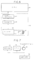
- Fig.6 shows a block diagram of the receiver 50.
- the receiver 50 has a resonance circuit comprising an electromagnetic induction coil 60 and a capacitor 61 in parallel connection.
- the resonance circuit receives the radio signal from the transmitter (electromagnetic induction coil 38).
- a detector 62 is connected to the resonance circuit 60 to amplify the received signal.
- a comparator 63 compares the amplified signal from the detector 62 with a predetermined threshold voltage level, thus forming a train of pulses.
- a pulse processing circuit 64 counts the pulses from the comparator 63. Further the pulse processing circuit 64 generates an end-of-pulse signal when the pulse train has ended. In response to the end-of-pulse signal, CPU 51 reads the pulse count from the pulse processing circuit 64.
- Fig.7 is a circuit diagram of the power supply 58 and associated control in accordance with the first embodiment.
- the power supply 58 is directly connected to the receiver 50 and CPU 51 to always supply to the electric power to them.
- the power supply 58 selectively supplies the electric power to the other parts (for example, the display driver 56 and display device 57 in Fig.5) through a transistor 60.
- CPU 51 controls the transistor 60 as follows. It turns on the transistor 60 when detecting that the bicycle 11 starts running. CPU 51 turns off the transistor 60 when the bicycle 11 is stopped. In this manner, CPU 51 automatically controls the electric power supply, saving the wasteful power consumption.
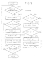
- the operation and display device 17 of the first embodiment monitors the rotation signal transmitted from the rotation detector 16P via the receiver 50.
- CPU 51 in the operation and display device starts a software timer in RAM 53 (step S302).
- a running condition flag is "stopped” (step S303) as in the case of Z point in Fig.8, it means that the vehicle starts running.
- CPU 51 turns on the transistor 60 (Fig.6) to start the supply of the electric power to the display device 57 etc. (step S304) and sets the flag to "run” (step S305).
- the CPU 51 computes the running condition (vehicle speed and traveled distance) and displays the computed running condition on the display device 57.
- step S307 If the receiver does not receive the rotation signal (S301) and if the flag is "run” (step S307), the CPU 51 increments the software timer (step S308).
- the software timer is timed out (step S309) when the receiver 50 does not receive the rotation signal for a predetermined time (for example, one minute). This timing is indicated by a point Y in Fig.8.
- CPU 51 turns off the transistor 60 to stop the supply of the electric power to the display device 57 etc. (step 5310) and sets the running condition flag to "stopped" (step 5311).
- the cycle computer of the third embodiment is essentially the same as that of the first embodiment in terms of overall arrangement (Fig.1), appearance (Fig.2), and the operation and display device 17 structure (Fig.5).
- the cycle computer of the second embodiment employs the rotation detector 16P of the type shown in Fig.3 described in conjunction with the first embodiment.
- the cycle computer of the second embodiment employs, however, a unique receiver 50M shown in Fig.10 to monitor the battery condition of the rotation detector 16P.
- Fig.10 shows a block diagram of the receiver 50M.
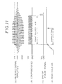
- Fig.11 shows a timing chart of the receiver of Fig.10.
- the receiver 50M receives the radio rotation signal transmitted from the rotation detector 16P by means of the induction coil 60 combined with the parallel capacitor 61.
- the detector 62 amplifies the received rotation signal as shown in Fig.11(a).
- the comparator 63 compares the amplified rotation signal with a predetermined threshold voltage level (Vth), thus shaping it into a pulse train as shown in Fig.11(b).
- the pulse processing circuit 64 counts the pulses in the pulse train to provide the pulse count to CPU 51. At the end of the pulse train, the pulse processing circuit 64 generates an end-of-pulse signal shown in Fig.11(c).
- the peak-hold circuit 65 detects and holds a peak voltage of the rotation signal from the detector 62, as shown in Fig.11(d).
- the analog-to-digital converter (ACD) 66 converts the analog peak voltage held by the peak-hold circuit 65 into a corresponding digital signal.
- CPU 51 In response to the end-of-pulse signal CPU 51 reads the pulse count from the pulse processing circuit 64, and the peak voltage data from ADC 66, respectively.
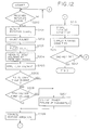
- Fig.12 is a flow chart of the operation and device 17 of the second embodiment.
- the reed switch 30 in the rotation detector 16P turns on each time when the magnet 14 passes by the reed switch, causing the radio transmitter to send the radio rotation signal.
- the operation and display device 17 receives the radio rotation signal by the resonance circuit (60, 62) in the receiver 50M (S200).
- the detector 62 in the receiver amplifies the received rotation signal (S201).
- the comparator 63 wave-shapes the amplified rotation signal into a train of pulses.
- the pulse processing circuit 64 counts the pulses (S202). Concurrently, the peak-hold circuit detects and holds the peak voltage of the rotation signal. At the end of the pulse train, the pulse processing circuit 64 generates the end-of-pulse signal, thus requesting CPU 51 to read and store the pulse count from the pulse processing circuit 64 and the peak voltage signal from the peak-hold circuit via ADC 66 (S203, S205).
- CPU 51 tests the strength of the received rotation signal to determined the battery condition of the rotation detector 16P. Specifically, CPU 51 compares the pulse count of the received rotation signal with a predetermined number (S206). Further, CPU 51 compares the peak voltage of the received signal with a predetermined voltage level (S208). If the pulse count is less than the predetermined number or if the peak voltage is lower than the predetermined voltage level, CPU 51 visually indicates the power failure of the rotation detector 16P (transmitter) on the display device 57.
- CPU 51 After testing the battery condition of the rotation detector 16P, CPU 51 computes the running condition of the bicycle 11 (S209). To this end, CPU 51 measures the time interval between the rotation signals and counts the rotation signals. The bicycle speed (per hour) is computed by (3600/time interval ⁇ wheel circumference). The traveled distance is obtained by multiplying the count of the rotation signals by the wheel circumference. CPU 51 stores the results of the computation in RAM 53 (5210) and displays them on the display device 57 (S211).
- the cycle computer of the third embodiment has the feature of automatically determining and indicating the battery condition of the rotation detector 16P.
- the operation and display device 17 monitors the strength of the received rotation signals sent from the rotation detector 16P.
- the device 17 detects reduced capacity of the battery in the rotation detector 16P and provides the alarm message of the power failure.
- the feature does not increase the cost or complexity of the cycle computer since no additional circuit is required in the rotation detector 16P.
- the cycle computer of the first embodiment can readily be combined with that of the second embodiment such that the combined cycle computer has both the feature of controlling the electric power supply in the operation and display device and the feature of automatically determining the battery condition of the rotation detector.
- the rotation detector (first device) may be connected by a cable to the operation and display device (second device). This will eliminate the radio transmitter and receiver from the cycle computer so that the output of the detector 31 or 31P may directly be connected to CPU 51. If desired, the rotation detector and the operation and display device may share a common battery.
- an alarm buzzer or voice message may be employed to warn the user of the power failure of the rotation detector.
- the invention can also apply to vehicles other than the bicycle, such as electric cars, automobiles.
Landscapes
- Physics & Mathematics (AREA)
- General Physics & Mathematics (AREA)
- Engineering & Computer Science (AREA)
- Radar, Positioning & Navigation (AREA)
- Remote Sensing (AREA)
- Arrangements For Transmission Of Measured Signals (AREA)
Claims (9)
- Gerät zur Messung eines Bewegungszustandes eines Fahrzeuges mit einer ersten Vorrichtung (16P) und einer zweiten Vorrichtung (17), die von der ersten Vorrichtung getrennt ist, wobei die erste Vorrichtung eine Rotationsdetektoreinrichtung (14, 30, 31P) zur Erfassung der Rotation eines Rades des Fahrzeuges, um ein Rotationssignal zu erzeugen, eine Sendeeinrichtung (33-35, 38-40), die mit der Rotationsdetektoreinrichtung zur Übertragung des Rotationssignals verbunden ist, und eine erste Batterieeinrichtung (Vcc) zur Bereitstellung elektrischer Leistung an die Rotationsdetektoreinrichtung und die Sendeeinrichtung umfaßt, wobei die zweite Vorrichtung eine Empfangseinrichtung (50M;60-62) zum Empfang des Rotationssignals, das von der Sendeeinrichtung übertragen wird, eine Berechnungseinrichtung (51) zur Berechnung des Bewegungszustandes des Fahrzeuges aus dem empfangenen Rotationssignal, eine Anzeigeeinrichtung (57) zur Anzeige des berechneten Bewegungszustandes und eine zweite Batterieeinrichtung (58) zur Bereitstellung elektrischer Leistung an die Empfangseinrichtung, die Berechnungseinrichtung und die Anzeigeeinrichtung umfaßt,
dadurch gekennzeichnet, daß
die zweite Vorrichtung außerdem eine Batteriezustandsfeststellungseinrichtung (62-66, 51) zur Bestimmung eines Zustandes der ersten Batterieeinrichtung in der ersten Vorrichtung unter Verwendung der Stärke des Rotationssignals, das von der Empfangseinrichtung empfangen wird, umfaßt. - Gerät nach Anspruch 1, wobei die Empfangseinrichtung umfaßt:eine Umformungseinrichtung (63) zur Umformung des empfangenen Rotationssignals in Impulse;eine Zähleinrichtung (64) zur Zählung der Impulse, um einen Impulszählwert bereitzustellen; undeine Einrichtung (51, S206) zur Bestimmung der Kapazität der Batterieeinrichtung basierend auf dem Impulszählwert der Zähleinrichtung.
- Gerät nach Anspruch 1 oder 2, wobei die Batteriezustandserfassungseinrichtung umfaßt:eine Spitzenwerthalteeinrichtung (65) zum Erfassen und Halten einer Spitzenspannung des empfangenen Rotationssignals;eine Einrichtung (51, S208) zur Bestimmung der Kapazität der Batterieeinrichtung basierend auf der Spitzenspannung.
- Gerät nach Anspruch 1, wobei die Batteriezustandsbestimmungseinrichtung umfaßt:eine Umformungseinrichtung (63) zur Umformung des empfangenen Rotationssignals in Impulse;eine Zähleinrichtung (64) zur Zählung der Impulse, um einen Impulszählwert bereitzustellen;eine Spitzenwerthalteeinrichtung (65) zum Erfassen und Halten einer Spitzenspannung des empfangenen Rotationssignals; undeine Einrichtung (51, S206, S208) zur Bestimmung der Kapazität der Batterieeinrichtung basierend auf dem Impulszählwert der Zähleinrichtung und der Spitzenspannung von der Spitzenwerthalteeinrichtung.
- Gerät nach einem der Ansprüche 1 bis 4, wobei die zweite Einrichtung außerdem eine Warneinrichtung (S207, 57) umfaßt, um vor einem Ausfall der Stromversorgung der ersten Vorrichtung zu warnen, wenn die Batteriezustandserfassungseinrichtung eine verminderte Kapazität der Batterieeinrichtung erfaßt.
- Gerät nach Anspruch 5, wobei die Warneinrichtung eine Anzeigevorrichtung (57) zur Anzeige einer Warnnachricht über den Ausfall der Stromversorgung umfaßt.
- Gerät nach einem der Ansprüche 1 bis 6, wobei die Sendeeinrichtung eine Funkübertragungsvorrichtung zur Übertragung des Rotationssignals in Form eines Funksignals umfaßt.
- Gerät nach einem der Ansprüche 1 bis 7, das an einem Fahrrad befestigt ist, um den Bewegungszustand des Fahrrades zu berechnen und anzuzeigen.
- Gerät nach einem der Ansprüche 1 bis 8, wobei die zweite Vorrichtung (17) außerdem umfaßt:eine Bestimmungseinrichtung (51, S301-S303, S307-S309) zur Überwachung des Rotationssignals, um festzustellen, ob sich das Fahrzeug bewegt oder ob es angehalten ist; undeine Steuereinrichtung (51, S310) zum Beenden der elektrischen Stromversorgung, wenn die Bestimmungseinrichtung herausfindet, daß das Fahrzeug angehalten ist.
Applications Claiming Priority (4)
| Application Number | Priority Date | Filing Date | Title |
|---|---|---|---|
| JP273115/93 | 1993-10-04 | ||
| JP5273115A JPH07104042A (ja) | 1993-10-04 | 1993-10-04 | 電圧検出装置 |
| JP5317338A JPH07147701A (ja) | 1993-11-22 | 1993-11-22 | 走行状態検出装置 |
| JP317338/93 | 1993-11-22 |
Publications (2)
| Publication Number | Publication Date |
|---|---|
| EP0650031A1 EP0650031A1 (de) | 1995-04-26 |
| EP0650031B1 true EP0650031B1 (de) | 1998-08-19 |
Family
ID=26550521
Family Applications (1)
| Application Number | Title | Priority Date | Filing Date |
|---|---|---|---|
| EP94115498A Expired - Lifetime EP0650031B1 (de) | 1993-10-04 | 1994-09-30 | Vorrichtung zur Messung einer Fahrzeugbewegung |
Country Status (3)
| Country | Link |
|---|---|
| US (1) | US5511435A (de) |
| EP (1) | EP0650031B1 (de) |
| DE (1) | DE69412564T2 (de) |
Cited By (1)
| Publication number | Priority date | Publication date | Assignee | Title |
|---|---|---|---|---|
| CN106767891A (zh) * | 2016-12-10 | 2017-05-31 | 俞钟晓 | 一种人力三轮车服务计量装置 |
Families Citing this family (20)
| Publication number | Priority date | Publication date | Assignee | Title |
|---|---|---|---|---|
| JP3319050B2 (ja) * | 1993-06-29 | 2002-08-26 | カシオ計算機株式会社 | 走行状態検出装置 |
| US5690410A (en) * | 1995-10-23 | 1997-11-25 | Lin; Tzu-Lung | Light device for a bicycle |
| DE19713044A1 (de) * | 1997-04-01 | 1998-10-15 | Ulrich Rittner | System zur Messung und Auswertung von Entfernung und Geschwindigkeit bei Rollschuhen, Skateboards und In-Line-Skates |
| US6016458A (en) * | 1998-08-20 | 2000-01-18 | Robinson; Alan David | Vehicular speed management system |
| US6213237B1 (en) * | 1998-10-23 | 2001-04-10 | David Willman | Motorcycle stop support wheels |
| US6646432B1 (en) * | 1998-11-04 | 2003-11-11 | Meritor Heavy Vehicle Systems, Llc | Electronic odometer integrated into vehicle axle and wheel hub |
| IT1320289B1 (it) * | 2000-03-29 | 2003-11-26 | Campagnolo Srl | Sistema per il trasferimento di dati, ad esempio per cicli qualibiciclette da competizione. |
| FR2828285B1 (fr) | 2001-08-03 | 2004-02-13 | Mavic Sa | Dispositif de mesure des parametres de roulage d'une bicyclette |
| JP3727292B2 (ja) * | 2002-08-20 | 2005-12-14 | 株式会社シマノ | 自転車用電装品駆動装置 |
| US7768405B2 (en) * | 2003-12-12 | 2010-08-03 | Semiconductor Energy Laboratory Co., Ltd | Semiconductor device and manufacturing method thereof |
| US7360421B2 (en) * | 2005-07-01 | 2008-04-22 | Adi Weber | Detachable angular speed sensing system |
| US20070054778A1 (en) * | 2005-08-29 | 2007-03-08 | Blanarovich Adrian M | Apparatus and system for measuring and communicating physical activity data |
| DE102005041458B3 (de) * | 2005-08-31 | 2007-06-14 | Trelock Gmbh | Verfahren zur drahtlosen Datenübertragung bei einem Fahrradcomputer |
| US7878521B2 (en) * | 2007-04-16 | 2011-02-01 | Trek Bicycle Corporation | Bicycle frame with device cavity |
| US8689629B2 (en) * | 2011-09-08 | 2014-04-08 | Vp Components Co., Ltd. | Sensing unit for bicycle speedometer |
| USD712768S1 (en) * | 2013-04-24 | 2014-09-09 | Cateye Co., Ltd. | Rotation detector for a bicycle |
| DE102014213943A1 (de) * | 2014-07-17 | 2016-01-21 | Robert Bosch Gmbh | Vorrichtung und Verfahren zur Erzeugung eines Geschwindigkeitswertes |
| GB2563398B (en) * | 2017-06-12 | 2021-04-21 | John Jones Peter | System of, and method for, determining the position and speed of a vehicle |
| WO2018228631A1 (de) * | 2017-06-14 | 2018-12-20 | Badass eBikes GmbH | Vorrichtung zum steuern und/oder regeln von geschwindigkeiten eines elektroleichtfahrzeugs, aufsetzbox und verfahren zur verwendung |
| DE102022205998A1 (de) | 2022-06-14 | 2023-12-14 | Robert Bosch Gesellschaft mit beschränkter Haftung | Signalgeber zur Ermittlung einer Fahrzeuggeschwindigkeit und Fahrzeug mit einem Signalgeber |
Family Cites Families (14)
| Publication number | Priority date | Publication date | Assignee | Title |
|---|---|---|---|---|
| FR2308910A1 (fr) * | 1975-04-21 | 1976-11-19 | Genzling Claude | Dispositif compteur-tachymetre integre pour bicyclette |
| US4007419A (en) * | 1975-10-02 | 1977-02-08 | Richard Jasmine | Digital bicycle speedometer-odometer |
| JPS59172745A (ja) * | 1983-03-22 | 1984-09-29 | Matsushita Electronics Corp | 半導体装置の電極形成方法 |
| JPS60118711U (ja) * | 1984-01-20 | 1985-08-10 | 株式会社キャットアイ | 自転車用走行データ表示装置 |
| JPS60118712U (ja) * | 1984-01-20 | 1985-08-10 | 株式会社 津山金属製作所 | 自転車用走行データ表示装置 |
| JPS60118713U (ja) * | 1984-01-20 | 1985-08-10 | 株式会社キャットアイ | 自転車用走行データ表示装置 |
| DE3622632C2 (de) * | 1986-07-05 | 1995-11-30 | Fichtel & Sachs Ag | Elektronisches Gerät zur Messung und Anzeige der Geschwindigkeit und weiterer Daten bei einem Fahrrad |
| KR910006967B1 (ko) * | 1987-11-18 | 1991-09-14 | 가시오 게이상기 가부시기가이샤 | 반도체 장치의 범프 전극 구조 및 그 형성 방법 |
| JPH01152311A (ja) * | 1987-12-09 | 1989-06-14 | Nissan Motor Co Ltd | 車両用電子式オドトリップメータ |
| US5008647A (en) * | 1989-02-06 | 1991-04-16 | Orleander S.A. | Wireless bicycle wheel monitor system |
| JPH0351376U (de) * | 1989-09-27 | 1991-05-20 | ||
| JPH03154871A (ja) * | 1989-11-13 | 1991-07-02 | Nippon Seimitsu Sokki Kk | 自転車の速度計 |
| EP0516113A3 (en) * | 1991-05-31 | 1993-06-30 | Ppg Industries, Inc. | Disk mounting arrangement and wireless angular velocity detector |
| US5177432A (en) * | 1991-05-31 | 1993-01-05 | Ppg Industries, Inc. | Wireless velocity detector for a bicycle having a rotating AC magnetic field and receiver coils |
-
1994
- 1994-09-30 DE DE69412564T patent/DE69412564T2/de not_active Expired - Fee Related
- 1994-09-30 EP EP94115498A patent/EP0650031B1/de not_active Expired - Lifetime
- 1994-09-30 US US08/316,788 patent/US5511435A/en not_active Expired - Lifetime
Cited By (2)
| Publication number | Priority date | Publication date | Assignee | Title |
|---|---|---|---|---|
| CN106767891A (zh) * | 2016-12-10 | 2017-05-31 | 俞钟晓 | 一种人力三轮车服务计量装置 |
| CN106767891B (zh) * | 2016-12-10 | 2020-06-12 | 奉化市中新阀门有限公司 | 一种人力三轮车服务计量装置 |
Also Published As
| Publication number | Publication date |
|---|---|
| HK1013435A1 (en) | 1999-08-27 |
| EP0650031A1 (de) | 1995-04-26 |
| DE69412564D1 (de) | 1998-09-24 |
| DE69412564T2 (de) | 1998-12-24 |
| US5511435A (en) | 1996-04-30 |
Similar Documents
| Publication | Publication Date | Title |
|---|---|---|
| US5511435A (en) | Apparatus for measuring vehicle running condition | |
| US6967571B2 (en) | Tire condition monitoring apparatus | |
| US6232875B1 (en) | Apparatus and method for controlling a tire condition module of a vehicle tire | |
| KR20030069094A (ko) | 타이어 상태 감시장치의 송신기 및 타이어 상태 감시장치 | |
| US7391308B2 (en) | Monitoring device, transceiver system and its control method | |
| US6938467B2 (en) | Transmitter of tire condition monitoring apparatus | |
| JP2003508298A (ja) | 乗り物のタイヤ内の圧力を監視し、無線で信号により通知するための装置 | |
| JP6128136B2 (ja) | タイヤ空気圧センサユニット、タイヤ空気圧報知装置、および、車両 | |
| EP1884422B1 (de) | Fahrzeugsteuerungsvorrichtung und Fahrzeug damit | |
| JP3982830B2 (ja) | 遠隔タイヤ圧力監視システム | |
| WO1997017218A1 (en) | Tyre mileage monitoring apparatus and method | |
| JP2009184405A (ja) | タイヤ回転検出装置、タイヤ回転検出方法及びタイヤ監視装置 | |
| JP3475458B2 (ja) | 走行状態検出装置および走行状態検出用受信機 | |
| JP3319050B2 (ja) | 走行状態検出装置 | |
| JP5251674B2 (ja) | タイヤ空気圧監視装置 | |
| JP3567473B2 (ja) | 充電装置および走行体用コンピュータ | |
| US5491476A (en) | Magnetically triggered elapsed time indicator | |
| US5003704A (en) | Distance measuring device and method for use with vehicles | |
| HK1013435B (en) | Apparatus for measuring vehicle running condition | |
| US7437921B2 (en) | Assembly including a pressure sensor, with an activation module, and a microprocessor for measurement and control purposes | |
| JP2003240660A (ja) | タイヤ状態監視装置の送信機及びタイヤ状態監視装置 | |
| JPH0717450A (ja) | 走行状態検出装置 | |
| JP3951947B2 (ja) | タイヤ空気圧検出装置 | |
| JP3362460B2 (ja) | 走行状態検出装置 | |
| JPH07147701A (ja) | 走行状態検出装置 |
Legal Events
| Date | Code | Title | Description |
|---|---|---|---|
| PUAI | Public reference made under article 153(3) epc to a published international application that has entered the european phase |
Free format text: ORIGINAL CODE: 0009012 |
|
| 17P | Request for examination filed |
Effective date: 19940930 |
|
| AK | Designated contracting states |
Kind code of ref document: A1 Designated state(s): DE FR GB |
|
| 17Q | First examination report despatched |
Effective date: 19961128 |
|
| GRAG | Despatch of communication of intention to grant |
Free format text: ORIGINAL CODE: EPIDOS AGRA |
|
| GRAG | Despatch of communication of intention to grant |
Free format text: ORIGINAL CODE: EPIDOS AGRA |
|
| GRAG | Despatch of communication of intention to grant |
Free format text: ORIGINAL CODE: EPIDOS AGRA |
|
| GRAH | Despatch of communication of intention to grant a patent |
Free format text: ORIGINAL CODE: EPIDOS IGRA |
|
| GRAH | Despatch of communication of intention to grant a patent |
Free format text: ORIGINAL CODE: EPIDOS IGRA |
|
| RAP1 | Party data changed (applicant data changed or rights of an application transferred) |
Owner name: CASIO COMPUTER CO., LTD. |
|
| GRAA | (expected) grant |
Free format text: ORIGINAL CODE: 0009210 |
|
| AK | Designated contracting states |
Kind code of ref document: B1 Designated state(s): DE FR GB |
|
| REF | Corresponds to: |
Ref document number: 69412564 Country of ref document: DE Date of ref document: 19980924 |
|
| ET | Fr: translation filed | ||
| PLBE | No opposition filed within time limit |
Free format text: ORIGINAL CODE: 0009261 |
|
| STAA | Information on the status of an ep patent application or granted ep patent |
Free format text: STATUS: NO OPPOSITION FILED WITHIN TIME LIMIT |
|
| 26N | No opposition filed | ||
| PGFP | Annual fee paid to national office [announced via postgrant information from national office to epo] |
Ref country code: FR Payment date: 20010911 Year of fee payment: 8 |
|
| PGFP | Annual fee paid to national office [announced via postgrant information from national office to epo] |
Ref country code: GB Payment date: 20011003 Year of fee payment: 8 |
|
| PGFP | Annual fee paid to national office [announced via postgrant information from national office to epo] |
Ref country code: DE Payment date: 20011015 Year of fee payment: 8 |
|
| REG | Reference to a national code |
Ref country code: GB Ref legal event code: IF02 |
|
| PG25 | Lapsed in a contracting state [announced via postgrant information from national office to epo] |
Ref country code: GB Free format text: LAPSE BECAUSE OF NON-PAYMENT OF DUE FEES Effective date: 20020930 |
|
| PG25 | Lapsed in a contracting state [announced via postgrant information from national office to epo] |
Ref country code: DE Free format text: LAPSE BECAUSE OF NON-PAYMENT OF DUE FEES Effective date: 20030401 |
|
| GBPC | Gb: european patent ceased through non-payment of renewal fee |
Effective date: 20020930 |
|
| PG25 | Lapsed in a contracting state [announced via postgrant information from national office to epo] |
Ref country code: FR Free format text: LAPSE BECAUSE OF NON-PAYMENT OF DUE FEES Effective date: 20030603 |
|
| REG | Reference to a national code |
Ref country code: FR Ref legal event code: ST |