EP0650045A1 - Prozess und Gerät zur Charakterisierung, Optimierung und automatischer Kontrolle einer Analyse mittels Farbeindringverfahren - Google Patents
Prozess und Gerät zur Charakterisierung, Optimierung und automatischer Kontrolle einer Analyse mittels Farbeindringverfahren Download PDFInfo
- Publication number
- EP0650045A1 EP0650045A1 EP94402346A EP94402346A EP0650045A1 EP 0650045 A1 EP0650045 A1 EP 0650045A1 EP 94402346 A EP94402346 A EP 94402346A EP 94402346 A EP94402346 A EP 94402346A EP 0650045 A1 EP0650045 A1 EP 0650045A1
- Authority
- EP
- European Patent Office
- Prior art keywords
- image
- background noise
- analysis method
- detection sensitivity
- sensitivity
- Prior art date
- Legal status (The legal status is an assumption and is not a legal conclusion. Google has not performed a legal analysis and makes no representation as to the accuracy of the status listed.)
- Granted
Links
Images


Classifications
-
- G—PHYSICS
- G06—COMPUTING OR CALCULATING; COUNTING
- G06T—IMAGE DATA PROCESSING OR GENERATION, IN GENERAL
- G06T7/00—Image analysis
- G06T7/0002—Inspection of images, e.g. flaw detection
- G06T7/0004—Industrial image inspection
-
- G—PHYSICS
- G01—MEASURING; TESTING
- G01N—INVESTIGATING OR ANALYSING MATERIALS BY DETERMINING THEIR CHEMICAL OR PHYSICAL PROPERTIES
- G01N21/00—Investigating or analysing materials by the use of optical means, i.e. using sub-millimetre waves, infrared, visible or ultraviolet light
- G01N21/84—Systems specially adapted for particular applications
- G01N21/88—Investigating the presence of flaws or contamination
- G01N21/91—Investigating the presence of flaws or contamination using penetration of dyes, e.g. fluorescent ink
-
- G—PHYSICS
- G01—MEASURING; TESTING
- G01N—INVESTIGATING OR ANALYSING MATERIALS BY DETERMINING THEIR CHEMICAL OR PHYSICAL PROPERTIES
- G01N27/00—Investigating or analysing materials by the use of electric, electrochemical, or magnetic means
- G01N27/72—Investigating or analysing materials by the use of electric, electrochemical, or magnetic means by investigating magnetic variables
- G01N27/82—Investigating or analysing materials by the use of electric, electrochemical, or magnetic means by investigating magnetic variables for investigating the presence of flaws
- G01N27/83—Investigating or analysing materials by the use of electric, electrochemical, or magnetic means by investigating magnetic variables for investigating the presence of flaws by investigating stray magnetic fields
- G01N27/84—Investigating or analysing materials by the use of electric, electrochemical, or magnetic means by investigating magnetic variables for investigating the presence of flaws by investigating stray magnetic fields by applying magnetic powder or magnetic ink
-
- G—PHYSICS
- G06—COMPUTING OR CALCULATING; COUNTING
- G06T—IMAGE DATA PROCESSING OR GENERATION, IN GENERAL
- G06T7/00—Image analysis
- G06T7/0002—Inspection of images, e.g. flaw detection
- G06T7/0004—Industrial image inspection
- G06T7/001—Industrial image inspection using an image reference approach
-
- G—PHYSICS
- G06—COMPUTING OR CALCULATING; COUNTING
- G06T—IMAGE DATA PROCESSING OR GENERATION, IN GENERAL
- G06T2207/00—Indexing scheme for image analysis or image enhancement
- G06T2207/20—Special algorithmic details
- G06T2207/20036—Morphological image processing
-
- G—PHYSICS
- G06—COMPUTING OR CALCULATING; COUNTING
- G06T—IMAGE DATA PROCESSING OR GENERATION, IN GENERAL
- G06T2207/00—Indexing scheme for image analysis or image enhancement
- G06T2207/30—Subject of image; Context of image processing
- G06T2207/30108—Industrial image inspection
-
- G—PHYSICS
- G06—COMPUTING OR CALCULATING; COUNTING
- G06T—IMAGE DATA PROCESSING OR GENERATION, IN GENERAL
- G06T2207/00—Indexing scheme for image analysis or image enhancement
- G06T2207/30—Subject of image; Context of image processing
- G06T2207/30108—Industrial image inspection
- G06T2207/30164—Workpiece; Machine component
Definitions
- the invention relates to a method and a device for optimizing, characterizing and controlling a penetrant analysis method.
- the invention applies to the detection of surface defects on all types of parts by the so-called penetrant method, and more particularly to the automation, characterization and optimization of penetrant methods.
- the part to be examined is previously prepared so as to materialize the surface defects.
- the preparation consists in applying to the surface of the part a penetrating composition (also called indicator product) which contains a fluorescent or colored dye and which penetrates into the openings of the defects opening onto the surface of the part, then removing from the surface of this piece the excess of the penetrating composition before applying a developing composition.
- the developing composition plays the role of a blotter and causes the attraction, by capillary action outside the surface defects, of the liquid penetrating composition containing the fluorescent dye.
- the part is then exposed to suitable lighting conditions such as invisible light generating fluorescence, and the existence of the emerging defects is revealed by the emission of fluorescent light visible by the dye of the penetrating composition which has has been retained in cracks or cracks after the penetrating composition has been removed from the surface of the part.
- the penetrating composition comprises fluorescent pigments which, under the action of light situated in the range of ultraviolet rays, re-emit visible light generally situated in the range of green-yellow colors.
- the method is called fluorescent penetrant method.
- the known automatic methods generally have limited sensitivity and discrimination power due to several factors and in particular to the lighting conditions of the part to be inspected and to the conditions of preparation of the part before carrying out the inspection.
- lighting is achieved by means of a light source emitting ultraviolet radiation.
- the radiation is filtered by means of filters to select a range of wavelengths suitable for the penetrating composition chosen.
- Filters are also placed at the input of the camera to eliminate the parasitic radiations not originating from the penetrating composition.
- the use of these filters is not completely satisfactory because they consume energy and contribute to the size of the automatic control device.
- the filters do not have a bandwidth suitable for this type of application and it is in particular very difficult to eliminate the parasitic wavelengths around 400 nanometers.
- These wavelengths located at the limit of the visible generally have a very large energy; they pollute the images by causing reflections and influence the reliability of the control result by masking the crack information and by inducing parasitic indications called phantom defects.
- the reliability of the control of the part depends on the preparation process preceding the examination of the part and in particular on the choice of the penetrating composition and of the conditions for cleaning the part to remove the excess of the penetrating composition. ; the reliability of the result also depends on the camera and the processing of the images acquired by the video means.
- the present invention aims to overcome the drawbacks of known methods of penetrant analysis and in particular of fluorescent penetrant analysis methods, and to increase the reliability of the control of parts by these methods.
- the subject of the invention is an automatic process and device which makes it possible to characterize quantitatively the known methods of penetrant analysis, to compare these methods with each other, to optimize the various parameters which influence the reliability of the result obtained and to periodically check the previously optimized analysis method to ensure that there are no significant deviations in the method .
- the quantitative characterization of a penetrant analysis method consists in determining the detection sensitivity and the background noise generated by the analysis method by means of a processing of images acquired from one or more control samples prepared according to this method and subjected to appropriate and optimized lighting conditions.
- Optimization of the penetrant analysis method is carried out by looking for the influencing parameters and by looking for the value of these parameters which makes it possible to maximize the detection sensitivity and minimize the background noise.
- the previously optimized analysis method is checked using the same control samples, periodically checking that the detection sensitivity and the background noise have not deteriorated. Otherwise an alarm signal signals the malfunction and the cause of this malfunction is investigated.
- the automatic device comprises an illumination device suitable and optimized for fluorescent penetrant testing, in which the lighting of the room is carried out by a light source with ultraviolet radiation, and optimized by selecting a wavelength band centered on the excitation line of the indicator product, this wavelength band being sufficiently narrow to eliminate the wavelengths emitted by the light source in the visible spectrum, and in particular the wavelength located in the surrounding blue of 400 nanometers.
- the invention also relates to an automatic device for characterizing, optimizing and controlling a fluorescent penetrant analysis method
- an illumination device comprising an illumination device, a camera and an image processing device, characterized in that the device illumination comprises in series, a light source with ultraviolet radiation, a monochromator for selecting a wavelength band centered around the excitation wavelength of the indicator product, a light guide for focusing ultraviolet radiation on an area of the part to be checked.
- the parts are prepared using indicator products which provide as high a contrast as possible of the indication of crack with respect to the surface of the part.
- the indicator products are fluorescent pigments which light up brightly under ultraviolet light, the bottom of the surface remaining dark. The contrast obtained can be used for the automatic control of the room by raising the luminosity of the fluorescent indications by means of an appropriate photosensitive device and by exploiting the information thus obtained.
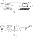
- FIG. 1 represents an image acquisition and processing device according to the invention.
- the device comprises a light emitting device 10, also called an illumination device, intended to illuminate an image field in which the part 11 to be checked is located.
- the part is then optically detected and electronically processed by a very sensitive television camera 12 at low light level and the image created is exploited by an image processing system 13, for example a computer.
- FIG. 2 represents an exemplary embodiment of the device for illuminating parts controlled by fluorescent penetrant testing, according to the invention.
- the illumination device comprises a light source 20 chosen as a function of the indicator product used during the part preparation cycle.
- the indicator product can be chosen such that it re-emits visible radiation whose wavelength is in the range of yellow-green colors between 450 and 550 nanometers under excitation of near centered ultraviolet radiation. on a wavelength of the order of 365 nanometers.
- the ultraviolet light source can be a laser or a multispectral lamp, for example a mercury vapor lamp.
- it is chosen at variable power so as to maintain constant illumination. It is also possible to adjust the illumination by shifting the spectrum of wavelengths emitted.
- the radiation emitted by the light source is transmitted through a monochromator 21 comprising at least one dispersive network and via a first optical device 22 for adaptation and focusing.
- the output signal of the monochromator 21 is directed through a light guide 23 via a second optical device 24 for adaptation and focusing.
- the role of the focusing devices 22 and 24 is to focus all the power emitted on the input slot of the monochromator and inside the light guide.
- the monochromator 21 is used as an emission filter and is chosen so as to be able to meet two essential constraints: on the one hand, the band of wavelengths selected around the excitation line of the indicator product, for example 365 nanometers, must not be too narrow so as to emit sufficient energy, on the other hand, it must be sufficiently selective to eliminate the wavelengths emitted by the source of light and located in the visible spectrum, in particular the wavelength located in the blue around 400 nanometers in the case of the use of a mercury vapor lamp.
- these two constraints can be satisfied by the use of a double monochromator with a short focal distance comprising two dispersive networks mechanically coupled and adjusted so as to select the same wavelength.
- a thermal filter 25 can be arranged upstream of the monochromator 21, between the first focusing device 22 and the input of the monochromator 26 to limit the thermal power at the input of the monochromator.
- This thermal filter can for example be a system with double quartz walls separated by a vacuum plate. Cooling takes place by natural convection or by the circulation of a fluid.
- the light guide must faithfully transmit ultraviolet radiation, attenuating it as little as possible and without creating stray radiation.
- a liquid guide is preferably chosen for its qualities of flexibility and robustness, but it is also possible to use an optical fiber, for example silica, although this type of fiber is very fragile.
- the light guide 23 is provided at each of its ends with a focusing optic, not shown, for example quartz windows, in order to obtain a uniform illumination and to focus the ultraviolet radiation on a small area of the room, by example of dimension 25mm X 25mm.
- a focusing optic not shown, for example quartz windows, in order to obtain a uniform illumination and to focus the ultraviolet radiation on a small area of the room, by example of dimension 25mm X 25mm.
- the surface of the part is examined successively in small areas by moving, manually or automatically, the part or the acquisition assembly (the camera and the illumination device).
- the method consists in determining the detection sensitivity and the background noise generated by this method. For this, the penetrant analysis method is applied to one or more control samples with cracks on the surface.
- gauge blocks comprising cracks whose depth is known and having a good surface condition.
- brass shims coated with a nickel-chromium deposit of determined thickness and comprising cracks whose depth is equal to the thickness of the nickel-chromium deposit there are commercially available brass shims coated with a nickel-chromium deposit of determined thickness and comprising cracks whose depth is equal to the thickness of the nickel-chromium deposit.
- the shims are available for different thicknesses of nickel-chromium deposits between 5 and 100 micrometers. The use of these shims as control samples makes it possible to evaluate the detection sensitivity of the process.
- control samples chosen must be representative of the parts to be checked with regard to the material and the surface condition.
- the samples may be chosen from among the parts to be inspected or pieces of parts, or may be test pieces representative of the material and of the surface condition of the parts to be inspected.
- Each control sample is prepared beforehand to materialize surface defects using a penetrating composition. It is then subjected to the action of ultraviolet radiation coming from an illumination device, for example that described in relation to FIG. 2.
- the illumination device is adjusted so that the intensity of illumination is as constant and homogeneous as possible in order to obtain good quality and comparable images.
- Visible radiation re-emitted by the control sample is then detected and is converted into a video image by means of a video camera to constitute a digital image coded with a dynamic which is, for example, 256 gray levels.
- the camera is adjusted so as to obtain a gray level close to zero for the background.
- the sensitivity of the camera used depends on the depth of the cracks to be analyzed, the sensitivity of the penetrant used and the fineness desired for the result.
- the magnification of the camera is adjusted so as to always cover the same image field; for example, in the case of brass shims coated with a nickel-chromium deposit, the magnification of the camera is adjusted so that the cracks occupy the entire height of the image.
- the images are always integrated the same number of times (for example 256 times) in order to suppress noise.
- the images are used by an image processing device to extract the detection sensitivity and the background noise.
- FIG. 3 represents, in the form of a succession of functional blocks, the different stages of the image processing method according to the invention.
- the process takes place in two stages. Initially corresponding to steps 30 to 34, images Ci are acquired, step 30, from samples constituted, for example, of standard blocks and treated to extract on the one hand, a threshold value Si, step 31, which makes it possible to binarize the image in order to eliminate the artifacts and on the other hand, an index of sensitivity Ii, step 32. The detail of the processing carried out on these samples is described in conjunction with FIG. 4.
- Step 33 is a test making it possible to determine if there are other images Ci to be processed.
- step 34 If the test is positive, the iteration index i and the number n of processed images are incremented and steps 30 to 32 are carried out again with the following image. If the test is negative, the average I of the sensitivity indices Ii obtained for each image Ci, as well as the minimum threshold value S, are calculated in step 34.
- a second step corresponding to steps 35 to 39, images Fj are acquired, step 35, from samples made up of pieces or test pieces representative of pieces to be checked and processed to extract the noise rate Bj from them, step 37, after thresholding, step 36, the threshold value being the minimum threshold value S obtained during the determination of the average sensitivity index I.
- Step 38 is a test making it possible to determine whether there are other Fj images to be processed. If the test is positive, the iteration index j and the number m of processed images are incremented and steps 35 to 38 are carried out again with the following image. If the test is negative, the average B of the noise levels Bj obtained for each image Fj is calculated in a step 39 and the method is terminated.
- the values I and B respectively constitute the detection sensitivity and the background noise generated by the penetrant analysis method considered.
- FIG. 4 represents, in the form of functional blocks, the sub-steps of the method corresponding to the processing of the images Ci for the determination of a sensitivity index, according to the invention.
- the first step 311, of the processing consists, for each image, in checking whether the background of the image is homogeneous and corresponds to a given gray level, for example close to zero to 5 gray levels. If the background is not homogeneous and / or close to zero, in a step 312 is carried out a reshaping of the image which consists in eliminating the indications of the background.
- This operation can be carried out by different methods such as, for example, by acquiring a blank image and subtracting this image from the image Ci. It is also possible to eliminate the indications of the background either by correcting the image with respect to itself by means of morphological or frequency filtering, or by correcting the image with respect to a reference image.
- a grayscale image filtering is carried out. This filtering makes it possible to join discontinuous indications which correspond to a single crack. To be combined, the discontinuous indications must be close enough to appear continuous to the naked eye. Filtering can be done using filters of mathematical morphology or frequency filters.
- step 314 is carried out the calculation of the threshold value Si which makes it possible to binarize the image in order to eliminate the artifacts therefrom.
- the threshold value is chosen equal to twice the average luminance value of the luminance maxima.
- the factor two corresponds to a mid-height evaluation of the relevance of a luminance peak.
- the luminance maxima are obtained after performing image binarization operations with an approximate threshold value obtained from the image histogram and chosen equal to the sum of the mean value and the standard deviation luminances of the image, skeletonization of the binarized image, and multiplication of the skeletonized binary image by the grayscale image.
- a second filtering is carried out, in step 315, on the binary image in order to eliminate the small artefacts which have not been deleted in step 313 during the filtering of the grayscale image.
- This second filtering includes linear expansion and linear erosion operations.
- step 316 consists in carrying out a test for searching for multiple indications making it possible to detect the cases where two very close cracks joined to form only one. for this, the filtered binary image is skeletonized in order to search for triple points which have three neighbors. If the test is positive, multiple indications are segmented in step 317. The segmentation consists in separating indications of crack which have merged. Since the triple points are generally far from the points situated at the ends, the segmentation is carried out after having searched for end points and having made a proximity test between the triple points and the end points.
- a step 318 is used to calculate the various parameters making it possible to determine a sensitivity index.
- the sensitivity index is for example chosen to be equal to the product of the length index and the resolution index.
- the length index being equal to the ratio of the length read over the theoretical length of the indications
- the resolution index being equal to the ratio of the average luminance of the luminance maxima to the read width of the indications.
- the theoretical length of a crack is known and corresponds to the height of the image when the samples are positioned so that the cracks appear vertical on the image.
- the number of cracks on a given sample is determined by prior observation of the sample under binocular.
- the width of the indications is obtained by calculating the ratio between the surface occupied by the points whose luminance is greater than the first threshold value and the length read of the indications.
- the method according to the invention makes it possible to optimize the influencing parameters by searching for the values of these parameters which makes it possible to maximize the detection sensitivity and to minimize the background noise.
- the optimization of a given analysis method therefore consists in selecting the influencing parameters, in seeking the values of these parameters which make it possible to maximize the detection sensitivity and in checking whether these parameter values do not degrade the background noise. .
- FIG. 5 represents, for a given method of analysis by fluorescent penetrant testing, an example of the effects of different parameters on the detection sensitivity. The results were obtained from gauge blocks. In this FIG. 5, the evolution of the sensitivity is visualized by six different parameters, each of these parameters taking three different values numbered from 1 to 3.
- the effects of each parameter on the detection sensitivity are measured relative to the average value taken by each of the parameters, the parameters being arranged in an order making it possible to display the most favorable values for optimizing the sensitivity detection.
- the detection sensitivity is better when the speed of the washing nozzle is low, when the washing nozzle used is nozzle number 1 and the water pressure for prewashing and washing the parts corresponds to the third value. considered.
- FIG. 6 represents an example of the effects of different parameters on the background noise generated by a given method of fluorescent penetrant analysis.
- this FIG. 6 makes it possible to verify that the choice of a washing nozzle speed not only makes it possible to maximize the sensitivity but also to minimize the background noise. Consequently, this parameter value makes it possible to optimize the chosen analysis method.
- the method according to the invention can also be used to periodically check that the analysis method has not derived. For this, periodically, the values of the detection sensitivity and of the background noise generated by the analysis method are checked from the same control samples as those which were used for the characterization of the analysis method. If the results have deteriorated, the causes of the malfunction of the analysis method are sought in order to remedy it.
- the present invention is not limited to the embodiment described precisely.
- the image processing method for determining the detection sensitivity and the background noise is not limited to fluorescent penetrant testing but can be applied to any method of penetrant analysis.
Landscapes
- Engineering & Computer Science (AREA)
- General Physics & Mathematics (AREA)
- Physics & Mathematics (AREA)
- Chemical & Material Sciences (AREA)
- Health & Medical Sciences (AREA)
- Life Sciences & Earth Sciences (AREA)
- Analytical Chemistry (AREA)
- Biochemistry (AREA)
- General Health & Medical Sciences (AREA)
- Immunology (AREA)
- Pathology (AREA)
- Quality & Reliability (AREA)
- Computer Vision & Pattern Recognition (AREA)
- Theoretical Computer Science (AREA)
- Electrochemistry (AREA)
- Chemical Kinetics & Catalysis (AREA)
- Investigating Materials By The Use Of Optical Means Adapted For Particular Applications (AREA)
Applications Claiming Priority (2)
| Application Number | Priority Date | Filing Date | Title |
|---|---|---|---|
| FR9312486A FR2711426B1 (fr) | 1993-10-20 | 1993-10-20 | Procédé et dispositif pour caractériser, optimiser et contrôler automatiquement une méthode d'analyse par ressuage. |
| FR9312486 | 1993-10-20 |
Publications (2)
| Publication Number | Publication Date |
|---|---|
| EP0650045A1 true EP0650045A1 (de) | 1995-04-26 |
| EP0650045B1 EP0650045B1 (de) | 1998-12-09 |
Family
ID=9452025
Family Applications (1)
| Application Number | Title | Priority Date | Filing Date |
|---|---|---|---|
| EP94402346A Expired - Lifetime EP0650045B1 (de) | 1993-10-20 | 1994-10-19 | Prozess und Gerät zur Charakterisierung, Optimierung und automatischer Kontrolle einer Analyse mittels Farbeindringverfahren |
Country Status (5)
| Country | Link |
|---|---|
| US (2) | US5570431A (de) |
| EP (1) | EP0650045B1 (de) |
| JP (1) | JP3095958B2 (de) |
| DE (1) | DE69415125T2 (de) |
| FR (1) | FR2711426B1 (de) |
Cited By (1)
| Publication number | Priority date | Publication date | Assignee | Title |
|---|---|---|---|---|
| EP1780534A1 (de) * | 2005-10-28 | 2007-05-02 | Turbomeca | Diagnose oder Parametrisierung einer Anlage zur Erkennung von zur Oberfläche von Teilen hin freiliegenden Defekten mittels Absonderung |
Families Citing this family (20)
| Publication number | Priority date | Publication date | Assignee | Title |
|---|---|---|---|---|
| US5737445A (en) * | 1995-04-20 | 1998-04-07 | The United States Of America As Represented By The United States Department Of Energy | Automated feature detection and identification in digital point-ordered signals |
| US6075590A (en) * | 1998-03-02 | 2000-06-13 | Applied Science Fiction, Inc. | Reflection infrared surface defect correction |
| US6140653A (en) * | 1998-03-27 | 2000-10-31 | Vysis, Inc. | Large-field fluorescence imaging apparatus |
| US6195891B1 (en) | 1999-04-26 | 2001-03-06 | Ge Aviation Service Operation | Method for identification and repair of indications in hardware |
| US6683641B1 (en) | 1999-09-01 | 2004-01-27 | United Technologies Corporation | Apparatus for inspecting the interior of hollow articles |
| EP1096249B1 (de) * | 1999-10-26 | 2013-05-01 | Hitachi-GE Nuclear Energy, Ltd. | Verfahren und Vorrichtung zur zerstörungsfreien Prüfung |
| GB2372315A (en) * | 2001-02-20 | 2002-08-21 | Digital Image Res Ltd | Determining the track condition in a transport system |
| US6427544B1 (en) * | 2001-03-14 | 2002-08-06 | United Technologies Corporation | Environmentally friendly ultra-high sensitivity liquid penetrant inspection process and system |
| US20020162966A1 (en) * | 2001-05-02 | 2002-11-07 | Yoder Lorinda L. | Method and apparatus for detecting surface defects in a plastic container |
| DE10150566B4 (de) * | 2001-10-15 | 2004-08-12 | Mr-Chemie Gmbh | Verfahren zum Prüfen von Kunststoffen |
| US6690460B2 (en) * | 2002-06-27 | 2004-02-10 | Taiwan Semiconductor Manufacturing Co., Ltd. | Real time detection of cracked quartz window |
| EP1828756A1 (de) * | 2004-12-16 | 2007-09-05 | Volvo Aero Corporation | Verfahren undvorrichtung zum nachweis von rissen in einem gegenstand |
| DE102007024058A1 (de) * | 2007-05-22 | 2008-11-27 | Illinois Tool Works Inc., Glenview | Vorrichtung und Verfahren zur Prüfmittel-Kontrolle |
| DE102011103003A1 (de) * | 2011-05-24 | 2012-11-29 | Lufthansa Technik Ag | Verfahren und Vorrichtung zur Rissprüfung eines Flugzeug- oder Gasturbinen-Bauteils |
| DE102012200767B4 (de) * | 2012-01-19 | 2014-11-13 | MTU Aero Engines AG | Verfahren zur zerstörungsfreien Prüfung von Werkstückoberflächen |
| JP2016090548A (ja) * | 2014-11-11 | 2016-05-23 | 株式会社東芝 | ひび割れ情報収集方法及びひび割れ情報収集プログラム |
| JP2016090547A (ja) * | 2014-11-11 | 2016-05-23 | 株式会社東芝 | ひび割れ情報収集装置及びひび割れ情報を収集するためのサーバ装置 |
| US10746667B2 (en) * | 2018-11-27 | 2020-08-18 | General Electric Company | Fluorescent penetrant inspection system and method |
| DE102019132585B4 (de) * | 2019-12-02 | 2022-06-09 | Schaeffler Technologies AG & Co. KG | Prüfsystem zur optischen Oberflächenprüfung eines Prüfkörpers |
| FR3129482B1 (fr) * | 2021-11-22 | 2024-05-24 | Safran Helicopter Engines | Systeme et procede de validation automatique de la conformite de reponse d’une chaine de ressuage |
Citations (7)
| Publication number | Priority date | Publication date | Assignee | Title |
|---|---|---|---|---|
| US3791198A (en) * | 1972-11-27 | 1974-02-12 | J Alburger | Testing panel for inspection penetrants having cracks of controlled depth and width |
| EP0184972A2 (de) * | 1984-12-11 | 1986-06-18 | United Technologies Corporation | Probestück zur Untersuchung von Oberflächendurchdringungsmitteln mit Auflage wechselnder Dicke |
| EP0231004A2 (de) * | 1986-01-28 | 1987-08-05 | Tiede Gmbh + Co Rissprüfanlagen | Verfahren zur Selbstkontrolle einer optoelektronischen Risserkennungseinrichtung, insbesondere nach dem Magnetpulververfahren |
| EP0282627A2 (de) * | 1987-03-16 | 1988-09-21 | Tiede Gmbh + Co Rissprüfanlagen | Verfahren zur zerstörungsfreien Rissprüfung von Werkstücken als Prüflingen nach dem Magnetpulver-bzw. dem Farbeindringverfahren |
| EP0309758A2 (de) * | 1987-09-23 | 1989-04-05 | Isotopen-Technik Dr. Sauerwein Gmbh | Verfahren und Vorrichtung zum Feststellen und Auswerten von Oberflächenrissen bei Werkstücken |
| DE3907732A1 (de) * | 1989-03-10 | 1990-09-13 | Isotopenforschung Dr Sauerwein | Verfahren zum ueberwachen einer vorrichtung zum automatischen feststellen und auswerten von oberflaechenrissen |
| US5115136A (en) * | 1990-08-06 | 1992-05-19 | Olympus Corporation | Ultraviolet remote visual inspection system |
Family Cites Families (13)
| Publication number | Priority date | Publication date | Assignee | Title |
|---|---|---|---|---|
| US4037961A (en) * | 1976-07-06 | 1977-07-26 | Baxter Travenol Laboratories, Inc. | System and apparatus for contour plotting the total luminescence spectrum of a sample |
| US4194217A (en) * | 1978-03-31 | 1980-03-18 | Bosch Francois J G Van Den | Method and apparatus for in-vivo spectroscopic analysis |
| US5004339A (en) * | 1979-02-27 | 1991-04-02 | Diffracto Ltd. | Method and apparatus for determining physical characteristics of objects and object surfaces |
| US4506980A (en) * | 1979-02-27 | 1985-03-26 | Diffracto Ltd. | Method and apparatus for determining physical characteristics of objects and object surfaces |
| JPS5769221A (en) * | 1980-10-16 | 1982-04-27 | Shimadzu Corp | Spectroscope |
| US4483615A (en) * | 1981-12-18 | 1984-11-20 | Owens-Illinois, Inc. | Method and apparatus for detecting checks in glass tubes |
| JPS603542A (ja) * | 1983-06-21 | 1985-01-09 | Mitsubishi Electric Corp | ビン検査装置 |
| JPS60207018A (ja) * | 1984-03-30 | 1985-10-18 | Shimadzu Corp | モノクロメ−タ |
| US4647199A (en) * | 1984-09-14 | 1987-03-03 | The Perkin-Elmer Corporation | Automatic shutter system |
| US4931949A (en) * | 1988-03-21 | 1990-06-05 | Monitoring Technology Corporation | Method and apparatus for detecting gear defects |
| US5001353A (en) * | 1989-01-17 | 1991-03-19 | Sumitomo Light Metal Industries, Ltd. | Method and apparatus to measure the thickness of coating films |
| JPH0695075B2 (ja) * | 1990-03-16 | 1994-11-24 | 工業技術院長 | 表面性状検出方法 |
| US5303026A (en) * | 1991-02-26 | 1994-04-12 | The Regents Of The University Of California Los Alamos National Laboratory | Apparatus and method for spectroscopic analysis of scattering media |
-
1993
- 1993-10-20 FR FR9312486A patent/FR2711426B1/fr not_active Expired - Fee Related
-
1994
- 1994-10-19 EP EP94402346A patent/EP0650045B1/de not_active Expired - Lifetime
- 1994-10-19 DE DE69415125T patent/DE69415125T2/de not_active Expired - Lifetime
- 1994-10-20 US US08/326,386 patent/US5570431A/en not_active Expired - Lifetime
- 1994-10-20 JP JP06255765A patent/JP3095958B2/ja not_active Expired - Fee Related
-
1995
- 1995-09-06 US US08/523,959 patent/US5563417A/en not_active Expired - Lifetime
Patent Citations (7)
| Publication number | Priority date | Publication date | Assignee | Title |
|---|---|---|---|---|
| US3791198A (en) * | 1972-11-27 | 1974-02-12 | J Alburger | Testing panel for inspection penetrants having cracks of controlled depth and width |
| EP0184972A2 (de) * | 1984-12-11 | 1986-06-18 | United Technologies Corporation | Probestück zur Untersuchung von Oberflächendurchdringungsmitteln mit Auflage wechselnder Dicke |
| EP0231004A2 (de) * | 1986-01-28 | 1987-08-05 | Tiede Gmbh + Co Rissprüfanlagen | Verfahren zur Selbstkontrolle einer optoelektronischen Risserkennungseinrichtung, insbesondere nach dem Magnetpulververfahren |
| EP0282627A2 (de) * | 1987-03-16 | 1988-09-21 | Tiede Gmbh + Co Rissprüfanlagen | Verfahren zur zerstörungsfreien Rissprüfung von Werkstücken als Prüflingen nach dem Magnetpulver-bzw. dem Farbeindringverfahren |
| EP0309758A2 (de) * | 1987-09-23 | 1989-04-05 | Isotopen-Technik Dr. Sauerwein Gmbh | Verfahren und Vorrichtung zum Feststellen und Auswerten von Oberflächenrissen bei Werkstücken |
| DE3907732A1 (de) * | 1989-03-10 | 1990-09-13 | Isotopenforschung Dr Sauerwein | Verfahren zum ueberwachen einer vorrichtung zum automatischen feststellen und auswerten von oberflaechenrissen |
| US5115136A (en) * | 1990-08-06 | 1992-05-19 | Olympus Corporation | Ultraviolet remote visual inspection system |
Non-Patent Citations (1)
| Title |
|---|
| M. STADTHAUS ET AL., MATERIALPRÜFUNG, vol. 30, no. 4, April 1988 (1988-04-01), pages 109 - 113 * |
Cited By (3)
| Publication number | Priority date | Publication date | Assignee | Title |
|---|---|---|---|---|
| EP1780534A1 (de) * | 2005-10-28 | 2007-05-02 | Turbomeca | Diagnose oder Parametrisierung einer Anlage zur Erkennung von zur Oberfläche von Teilen hin freiliegenden Defekten mittels Absonderung |
| FR2892815A1 (fr) * | 2005-10-28 | 2007-05-04 | Turbomeca | Diagnostic ou parametrage d'une installation de detection par ressuage de defauts debouchants a la surface de pieces |
| US7746458B2 (en) | 2005-10-28 | 2010-06-29 | Turbomeca | Diagnosing or determining parameters for an installation for detecting open defects in the surfaces of parts by sweating |
Also Published As
| Publication number | Publication date |
|---|---|
| FR2711426B1 (fr) | 1995-12-01 |
| DE69415125T2 (de) | 1999-05-27 |
| FR2711426A1 (fr) | 1995-04-28 |
| JPH07190959A (ja) | 1995-07-28 |
| JP3095958B2 (ja) | 2000-10-10 |
| DE69415125D1 (de) | 1999-01-21 |
| EP0650045B1 (de) | 1998-12-09 |
| US5563417A (en) | 1996-10-08 |
| US5570431A (en) | 1996-10-29 |
Similar Documents
| Publication | Publication Date | Title |
|---|---|---|
| EP0650045B1 (de) | Prozess und Gerät zur Charakterisierung, Optimierung und automatischer Kontrolle einer Analyse mittels Farbeindringverfahren | |
| EP0060160B1 (de) | Verfahren zur Untersuchung von Fehlern an Glasbahnen und Einrichtung zur Ausführung dieses Verfahrens | |
| FR2522149A1 (fr) | Procede et appareil de controle de defauts de surface d'une vis | |
| EP3735578B1 (de) | Verfahren und system zur optischen inspektion eines substrats | |
| CN113218966A (zh) | 用于光学滤光片的自动缺陷检测与映射 | |
| CA3137262A1 (fr) | Systeme et procede de detection de vitroceramique | |
| EP3404381B1 (de) | System und verfahren zur rauscharmen, hyperspektralen, zerstörungsfreien prozessinternen hochgeschwindigkeitsbeurteilung für die schnelle herstellung von verbundwerkstoffen | |
| JP2803443B2 (ja) | 表面検査方法およびその装置 | |
| FR2792725A1 (fr) | Procede et dispositif pour la detection de variations de proprietes optiques d'un echantillon liquide dans un processus d'analyse | |
| FR2737560A1 (fr) | Procede et dispositif pour quantifier in situ, par reflectometrie, la morphologie d'une zone localisee lors de la gravure de la couche superficielle d'une structure a couches minces | |
| EP0327416B1 (de) | Verfahren zur Kontrastoptimierung im Bild einer Probe | |
| WO1995012810A1 (fr) | Methode de controle de l'etat de surface d'une face d'un solide et dispositif associe | |
| EP3054284B1 (de) | Verfahren zum korrigieren eines von einer probe zurückgestreuten raman signals, und entsprechende vorrichtung | |
| FR3050528A1 (fr) | Procede et dispositif d’estimation de proprietes optiques d’un echantillon | |
| WO2022064147A1 (fr) | Procede d'analyse d'un echantillon biologique avec determination de la repartition spatiale de biomasse le long de l'axe optique | |
| JPH10267859A (ja) | 光ファイバ被覆層内の欠陥検出装置及び検査方法 | |
| FR3018603A1 (fr) | Dispositif d'analyse et d'imagerie d'une surface par deflectometrie et procede correspondant | |
| CA3137266A1 (fr) | Procede de detection de vitroceramique | |
| EP0668493B1 (de) | Verfahren und Vorrichtung zur Prüfung von wabenartigen Strukturen mit Hilfe von optischen Fasern | |
| FR2733596A1 (fr) | Procede et dispositif d'identification de particules | |
| JP4280967B2 (ja) | 浸透探傷試験方法及び該浸透探傷試験方法に用いる浸透探傷試験装置 | |
| FR2517827A1 (fr) | Procede et appareil de mesure par voie optique de la consistance d'une boue de pate | |
| FR2965924A1 (fr) | Procede et dispositif pour evaluer le pouvoir dispersant des huiles lubrifiantes. | |
| WO2024061843A1 (fr) | Microscope optique avec résonateur | |
| FR3151402A1 (fr) | Procédé de contrôle permettant de détecter au moins un défaut débouchant présent en surface d’une pièce mécanique pour aéronef |
Legal Events
| Date | Code | Title | Description |
|---|---|---|---|
| PUAI | Public reference made under article 153(3) epc to a published international application that has entered the european phase |
Free format text: ORIGINAL CODE: 0009012 |
|
| 17P | Request for examination filed |
Effective date: 19941105 |
|
| AK | Designated contracting states |
Kind code of ref document: A1 Designated state(s): DE FR GB IT SE |
|
| 17Q | First examination report despatched |
Effective date: 19970612 |
|
| GRAG | Despatch of communication of intention to grant |
Free format text: ORIGINAL CODE: EPIDOS AGRA |
|
| GRAG | Despatch of communication of intention to grant |
Free format text: ORIGINAL CODE: EPIDOS AGRA |
|
| GRAH | Despatch of communication of intention to grant a patent |
Free format text: ORIGINAL CODE: EPIDOS IGRA |
|
| GRAH | Despatch of communication of intention to grant a patent |
Free format text: ORIGINAL CODE: EPIDOS IGRA |
|
| GRAA | (expected) grant |
Free format text: ORIGINAL CODE: 0009210 |
|
| AK | Designated contracting states |
Kind code of ref document: B1 Designated state(s): DE FR GB IT SE |
|
| REF | Corresponds to: |
Ref document number: 69415125 Country of ref document: DE Date of ref document: 19990121 |
|
| GBT | Gb: translation of ep patent filed (gb section 77(6)(a)/1977) |
Effective date: 19990108 |
|
| PLBI | Opposition filed |
Free format text: ORIGINAL CODE: 0009260 |
|
| PLBQ | Unpublished change to opponent data |
Free format text: ORIGINAL CODE: EPIDOS OPPO |
|
| PLBF | Reply of patent proprietor to notice(s) of opposition |
Free format text: ORIGINAL CODE: EPIDOS OBSO |
|
| 26 | Opposition filed |
Opponent name: TIEDE GMBH & CO, RISSPRUEFANLAGEN Effective date: 19990909 |
|
| PLBF | Reply of patent proprietor to notice(s) of opposition |
Free format text: ORIGINAL CODE: EPIDOS OBSO |
|
| PLBL | Opposition procedure terminated |
Free format text: ORIGINAL CODE: EPIDOS OPPC |
|
| PLBM | Termination of opposition procedure: date of legal effect published |
Free format text: ORIGINAL CODE: 0009276 |
|
| STAA | Information on the status of an ep patent application or granted ep patent |
Free format text: STATUS: OPPOSITION PROCEDURE CLOSED |
|
| 27C | Opposition proceedings terminated |
Effective date: 20010526 |
|
| REG | Reference to a national code |
Ref country code: GB Ref legal event code: IF02 |
|
| REG | Reference to a national code |
Ref country code: FR Ref legal event code: TP Ref country code: FR Ref legal event code: CD |
|
| REG | Reference to a national code |
Ref country code: FR Ref legal event code: CD |
|
| PLAB | Opposition data, opponent's data or that of the opponent's representative modified |
Free format text: ORIGINAL CODE: 0009299OPPO |
|
| REG | Reference to a national code |
Ref country code: GB Ref legal event code: 732E Free format text: REGISTERED BETWEEN 20120517 AND 20120523 |
|
| PGFP | Annual fee paid to national office [announced via postgrant information from national office to epo] |
Ref country code: GB Payment date: 20120924 Year of fee payment: 19 Ref country code: SE Payment date: 20120924 Year of fee payment: 19 |
|
| PGFP | Annual fee paid to national office [announced via postgrant information from national office to epo] |
Ref country code: IT Payment date: 20120921 Year of fee payment: 19 |
|
| PGFP | Annual fee paid to national office [announced via postgrant information from national office to epo] |
Ref country code: DE Payment date: 20120924 Year of fee payment: 19 |
|
| PGFP | Annual fee paid to national office [announced via postgrant information from national office to epo] |
Ref country code: FR Payment date: 20130930 Year of fee payment: 20 |
|
| REG | Reference to a national code |
Ref country code: SE Ref legal event code: EUG |
|
| GBPC | Gb: european patent ceased through non-payment of renewal fee |
Effective date: 20131019 |
|
| REG | Reference to a national code |
Ref country code: DE Ref legal event code: R119 Ref document number: 69415125 Country of ref document: DE Effective date: 20140501 |
|
| PG25 | Lapsed in a contracting state [announced via postgrant information from national office to epo] |
Ref country code: GB Free format text: LAPSE BECAUSE OF NON-PAYMENT OF DUE FEES Effective date: 20131019 |
|
| PG25 | Lapsed in a contracting state [announced via postgrant information from national office to epo] |
Ref country code: SE Free format text: LAPSE BECAUSE OF NON-PAYMENT OF DUE FEES Effective date: 20131020 Ref country code: IT Free format text: LAPSE BECAUSE OF NON-PAYMENT OF DUE FEES Effective date: 20131019 Ref country code: DE Free format text: LAPSE BECAUSE OF NON-PAYMENT OF DUE FEES Effective date: 20140501 |