EP0650060A1 - Système de mesure de vitesse à haute résolution notamment pour commande électrique de porte - Google Patents
Système de mesure de vitesse à haute résolution notamment pour commande électrique de porte Download PDFInfo
- Publication number
- EP0650060A1 EP0650060A1 EP94116104A EP94116104A EP0650060A1 EP 0650060 A1 EP0650060 A1 EP 0650060A1 EP 94116104 A EP94116104 A EP 94116104A EP 94116104 A EP94116104 A EP 94116104A EP 0650060 A1 EP0650060 A1 EP 0650060A1
- Authority
- EP
- European Patent Office
- Prior art keywords
- pulses
- evaluation
- evaluation device
- evaluation method
- channel
- Prior art date
- Legal status (The legal status is an assumption and is not a legal conclusion. Google has not performed a legal analysis and makes no representation as to the accuracy of the status listed.)
- Ceased
Links
- 238000011156 evaluation Methods 0.000 claims abstract description 27
- 238000005259 measurement Methods 0.000 claims abstract description 22
- 230000005693 optoelectronics Effects 0.000 claims abstract description 7
- 230000000630 rising effect Effects 0.000 claims abstract description 4
- 238000000034 method Methods 0.000 description 4
- 230000003287 optical effect Effects 0.000 description 4
- 230000005540 biological transmission Effects 0.000 description 2
- 238000010586 diagram Methods 0.000 description 2
- 239000000463 material Substances 0.000 description 2
- GYTROFMCUJZKNA-UHFFFAOYSA-N triethyl triethoxysilyl silicate Chemical compound CCO[Si](OCC)(OCC)O[Si](OCC)(OCC)OCC GYTROFMCUJZKNA-UHFFFAOYSA-N 0.000 description 2
- 230000015572 biosynthetic process Effects 0.000 description 1
- 238000001514 detection method Methods 0.000 description 1
- 238000006073 displacement reaction Methods 0.000 description 1
- 239000002184 metal Substances 0.000 description 1
Images

Classifications
-
- G—PHYSICS
- G01—MEASURING; TESTING
- G01P—MEASURING LINEAR OR ANGULAR SPEED, ACCELERATION, DECELERATION, OR SHOCK; INDICATING PRESENCE, ABSENCE, OR DIRECTION, OF MOVEMENT
- G01P13/00—Indicating or recording presence, absence, or direction, of movement
- G01P13/02—Indicating direction only, e.g. by weather vane
- G01P13/04—Indicating positive or negative direction of a linear movement or clockwise or anti-clockwise direction of a rotational movement
- G01P13/045—Indicating positive or negative direction of a linear movement or clockwise or anti-clockwise direction of a rotational movement with speed indication
Definitions
- the invention relates to an evaluation method and an electronic evaluation device for pulses emitted by a multi-channel, in particular two-channel, optoelectronic tachometer on the drive motor of a mechanical device, in particular a door movement mechanism, with rising and falling edges, the pulses being output in a staggered manner on the individual channels to determine the direction of rotation of the motor.
- Optoelectronic tachometers are known, e.g. from Hewlett Packard (HP) the types HEDS and HEDM. These known tachometers are two- or three-channel optical decoders with a wheel provided with openings or marks, which rotates between an optical part with a light-emitting diode and a receiver part with distributed photodiodes. The photodiodes are arranged in such a way that pulses are offset by 90 ° on two channels.
- the difference between the types HEDM and HEDS of the known optical decoders consists only in the material of the rotating disk, on the one hand it is metal and on the other hand it is film-like material. This version is designed for very high resolutions.
- resolvers In the case of very slow movements of the drive motor, such devices, which are referred to as resolvers in a ready-to-install configuration, are arranged on the drive motor with a transmission gear in order to obtain a sufficient number of pulses per unit of time for determining an instantaneous speed.
- the speed measurement is carried out by measuring the time difference between the edges of the emitted pulses, in particular two successive pulses (period measurement).
- a complex transmission gear can usually be omitted. This is particularly the case if the speed measurement is carried out by taking into account at least two periods overlapping on the channels. After the passage of 2.5 pulses on one channel, four period measurements can be carried out on the two channels. In this way, a reliable mean value is obtained very quickly. Since measurements are always made over complete periods of the two channels, phase errors (position of the switching points in the channels) and the offset error between the channels play no role.
- the prerequisite is an exact position and formation of the openings or marks on the rotating disc, a measurement of the individual pulses, i.e. possible between the rising and falling flanks of individual pulses. In this way, a sufficiently reliable instantaneous speed value can also be obtained, if necessary, by evaluating only one period per channel. The speed resolution is increased even further.
- the times of the, preferably last two, measured periods are continuously taken over for consideration by a processor and the measurements prior to the last considered measurements are deleted.
- the last instantaneous value of the speed measurement is always stored in a memory.
- an electronic evaluation device which has at least two, preferably four, bit counters operating in parallel, to which a constant, fast counter clock pulse can be applied and from whose values the instantaneous speed value can be calculated.
- a direction of rotation evaluation unit and a rotation counter in the form of integrated subunits this results in a complete, preferably simple for door controls, be it normal electrical sliding doors, elevator doors or also revolving doors, suitable simple equipment that can be designed as a customer-specific IC.
- a programmable logic chip can also be used together with corresponding memory elements.
- line A denotes the pulses of one and line B the pulses of the other pulse output channel.
- the edges which, as shown here, belong to rectangular pulses, but can also belong to actually present trapezoidal pulses, are denoted continuously (for two periods) by 1 to 8.
- the associated counting status ("STATE") is designated by 1,2,3,4 etc.
- the direction of rotation is determined by the pulse train on the two channels A and B.
- the counting sequence 1,2,3 in the counting star above which "count up” stands, means, for example, clockwise rotation and the counting sequence 1,4,3, above which "count down” stands, means counterclockwise rotation.
- bit counter 12 denotes the bit counters, to which a fast clock cycle symbolically indicated by the arrows 11 and, via a controller 10, the edges of the pulses coming from the channels A and B are given.
- the speed is now determined in such a way that the bit counter 12 is started at edge 1.
- the counter reading is transferred to a unit 18 and the bit counter 12 is deleted and restarted.
- the bit counter 13 is started at edge 2.
- the counter reading is also transferred to the unit 18, the bit counter 13 is deleted and restarted.
- the bit counter 14 is started at edge 3.
- the counter reading is also transferred to the unit 18, the bit counter 14 is deleted and restarted.
- the bit counter 15 is started at edge 4.
- the counter reading is also transferred to the unit 18, the bit counter 15 is deleted and restarted.
- the current speed value is always in the unit 18, e.g. an 8-bit latch.
- a process interface 19 connects the evaluation device to the mechanical device to be controlled, for example an elevator door control.
- 16 denotes a direction of rotation evaluation unit.
- the resolution e.g. when using a film disc in the optoelectronic speed measuring device with 1024 markings
- the procedure according to the invention is so high that even the lowest speeds that result from opening and closing operations of sliding doors of all kinds are reliably detected.
- there is a surprisingly simple and accurate speed measurement which in principle can also be used as a speed measurement in an at least two-channel optical-electronic marking detection of a displacement sensor.
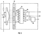
- FIG. 3 which shows an optoelectronic speed measuring device from Hewlett Packard (HP)
- 20 denotes a light-emitting diode
- 21 denotes an optical device arranged between the light-emitting diode 20 and a rotating disk 22.
- the Photodiodes 23 detect the light pulses that arise and convert them via a signal processor 24 and comparators 25 into electrical pulses that are output on channels A and B.
- 26 denotes an optionally available unit that counts full revolutions, which may be important for determining the position of doors. It is readily apparent that the measuring principle described above can also be applied to linear two-channel sensors. In both cases the unprecedentedly high resolution results with its very quick determination of the current speed or speed value.
Landscapes
- Physics & Mathematics (AREA)
- General Physics & Mathematics (AREA)
- Optical Transform (AREA)
- Elevator Door Apparatuses (AREA)
Applications Claiming Priority (2)
| Application Number | Priority Date | Filing Date | Title |
|---|---|---|---|
| DE4336133 | 1993-10-22 | ||
| DE4336133 | 1993-10-22 |
Publications (1)
| Publication Number | Publication Date |
|---|---|
| EP0650060A1 true EP0650060A1 (fr) | 1995-04-26 |
Family
ID=6500812
Family Applications (1)
| Application Number | Title | Priority Date | Filing Date |
|---|---|---|---|
| EP94116104A Ceased EP0650060A1 (fr) | 1993-10-22 | 1994-10-12 | Système de mesure de vitesse à haute résolution notamment pour commande électrique de porte |
Country Status (1)
| Country | Link |
|---|---|
| EP (1) | EP0650060A1 (fr) |
Citations (2)
| Publication number | Priority date | Publication date | Assignee | Title |
|---|---|---|---|---|
| US4050747A (en) * | 1976-04-17 | 1977-09-27 | Wabco Westinghouse Gmbh | Digital wheel speed circuit arranged to compensate for dimensional irregularities of sensor rotor member |
| DE3145162A1 (de) * | 1981-11-13 | 1983-05-26 | AEG-Kanis Turbinenfabrik GmbH, 8500 Nürnberg | Verfahren zur messung und ueberwachung der drehzahl von schnellaufenden maschinen |
-
1994
- 1994-10-12 EP EP94116104A patent/EP0650060A1/fr not_active Ceased
Patent Citations (2)
| Publication number | Priority date | Publication date | Assignee | Title |
|---|---|---|---|---|
| US4050747A (en) * | 1976-04-17 | 1977-09-27 | Wabco Westinghouse Gmbh | Digital wheel speed circuit arranged to compensate for dimensional irregularities of sensor rotor member |
| DE3145162A1 (de) * | 1981-11-13 | 1983-05-26 | AEG-Kanis Turbinenfabrik GmbH, 8500 Nürnberg | Verfahren zur messung und ueberwachung der drehzahl von schnellaufenden maschinen |
Non-Patent Citations (1)
| Title |
|---|
| RAOUL FONTENAY: "MESURES DE VITESSE OU DE POSITION: CODEUR OPTIQUE ANGULAIRE EN KIT", ELECTRONIQUE INDUSTRIELLE, no. 14, 15 April 1981 (1981-04-15), PARIS, pages 79 - 80, XP001120080 * |
Similar Documents
| Publication | Publication Date | Title |
|---|---|---|
| DE3018496C2 (fr) | ||
| DE69719148T2 (de) | Positionsgeber, kodierungsplatte, verfahren zur positionserfassung, zeitgeber und elektronisches gerät | |
| EP0575843B1 (fr) | Système de mesure angulaire | |
| EP0557265A1 (fr) | Capteur de rotation | |
| EP1193472A2 (fr) | Procédé et appareil pour la détermination de la position absolue des capteurs de déplacements et d'angles | |
| EP0530176B1 (fr) | Dispositif de mesure linéaire ou angulaire | |
| EP1102040A1 (fr) | Capteur de position | |
| AT392536B (de) | Lineares, inkrementales messsystem | |
| DE19639501A1 (de) | Tür oder Fenster mit einem motorisch angetriebenen Flügel | |
| DE19527588C2 (de) | Verfahren zum Prüfen von Zählern mit Anzeigen | |
| DE2159002C3 (de) | Vorrichtung zur Erfassung von relativen Lageänderungen in einem vorgegebenen Sollverhältnis bewegter Teile | |
| EP0943920A2 (fr) | Dispositif à capteur et procédé de transmission de données utilisant un tel dispositif à capteur | |
| DE3739271A1 (de) | Einrichtung zur weg- und geschwindigkeitsmessung bei spurgebundenen fahrzeugen | |
| DE3815530C2 (fr) | ||
| EP0650060A1 (fr) | Système de mesure de vitesse à haute résolution notamment pour commande électrique de porte | |
| DE9320721U1 (de) | Hochauflösendes Drehzahlmeßsystem, insbesondere für elektrische Türantriebe | |
| DE2829292C2 (de) | Vorrichtung zum Messen des Drehwinkels einer rotierenden Welle | |
| DE10212563A1 (de) | Verfahren und Vorrichtung zur Erfassung des Blendenöffnungswinkels einer verstellbaren Umlaufblende in einer Laufbildkamera | |
| DE102010013119A1 (de) | Drehgeber | |
| EP2533021B1 (fr) | Système de mesure de trajectoire linéaire et procédé de détermination d'une position d'une glissière en relation avec un rail de guidage | |
| DE4313497C2 (de) | Verfahren und Gerät zum Bestimmen von Richtung und Geschwindigkeit eines Objektes | |
| DE4009749C2 (fr) | ||
| DE3813754A1 (de) | Vorrichtung zur erfassung der winkelposition eines drehbaren koerpers | |
| DE19755157C2 (de) | Optisches Abtastsystem | |
| DE19604968C2 (de) | Verfahren zum Prüfen von inkrementalen Meßsystemen und Prüfgerät zur Durchführung des Verfahrens |
Legal Events
| Date | Code | Title | Description |
|---|---|---|---|
| PUAI | Public reference made under article 153(3) epc to a published international application that has entered the european phase |
Free format text: ORIGINAL CODE: 0009012 |
|
| AK | Designated contracting states |
Kind code of ref document: A1 Designated state(s): AT BE CH DE DK ES FR GB IT LI LU NL SE |
|
| 17P | Request for examination filed |
Effective date: 19950518 |
|
| 17Q | First examination report despatched |
Effective date: 19970325 |
|
| APAB | Appeal dossier modified |
Free format text: ORIGINAL CODE: EPIDOS NOAPE |
|
| APAD | Appeal reference recorded |
Free format text: ORIGINAL CODE: EPIDOS REFNE |
|
| APAB | Appeal dossier modified |
Free format text: ORIGINAL CODE: EPIDOS NOAPE |
|
| STAA | Information on the status of an ep patent application or granted ep patent |
Free format text: STATUS: THE APPLICATION HAS BEEN REFUSED |
|
| 18R | Application refused |
Effective date: 20030313 |
|
| APAF | Appeal reference modified |
Free format text: ORIGINAL CODE: EPIDOSCREFNE |