EP0650108B1 - Dispositif de régulation du débit d'une matière fluide - Google Patents
Dispositif de régulation du débit d'une matière fluide Download PDFInfo
- Publication number
- EP0650108B1 EP0650108B1 EP94402392A EP94402392A EP0650108B1 EP 0650108 B1 EP0650108 B1 EP 0650108B1 EP 94402392 A EP94402392 A EP 94402392A EP 94402392 A EP94402392 A EP 94402392A EP 0650108 B1 EP0650108 B1 EP 0650108B1
- Authority
- EP
- European Patent Office
- Prior art keywords
- receptacle
- common wall
- receptacles
- wall
- fluid
- Prior art date
- Legal status (The legal status is an assumption and is not a legal conclusion. Google has not performed a legal analysis and makes no representation as to the accuracy of the status listed.)
- Expired - Lifetime
Links
- 230000001105 regulatory effect Effects 0.000 title claims abstract description 14
- 239000012530 fluid Substances 0.000 title claims abstract description 11
- 239000000463 material Substances 0.000 title abstract description 16
- 239000007787 solid Substances 0.000 claims description 7
- 230000006866 deterioration Effects 0.000 description 1
- 230000000694 effects Effects 0.000 description 1
- 238000012423 maintenance Methods 0.000 description 1
- 238000011144 upstream manufacturing Methods 0.000 description 1
Images

Classifications
-
- G—PHYSICS
- G05—CONTROLLING; REGULATING
- G05D—SYSTEMS FOR CONTROLLING OR REGULATING NON-ELECTRIC VARIABLES
- G05D7/00—Control of flow
- G05D7/03—Control of flow with auxiliary non-electric power
-
- Y—GENERAL TAGGING OF NEW TECHNOLOGICAL DEVELOPMENTS; GENERAL TAGGING OF CROSS-SECTIONAL TECHNOLOGIES SPANNING OVER SEVERAL SECTIONS OF THE IPC; TECHNICAL SUBJECTS COVERED BY FORMER USPC CROSS-REFERENCE ART COLLECTIONS [XRACs] AND DIGESTS
- Y10—TECHNICAL SUBJECTS COVERED BY FORMER USPC
- Y10T—TECHNICAL SUBJECTS COVERED BY FORMER US CLASSIFICATION
- Y10T137/00—Fluid handling
- Y10T137/2931—Diverse fluid containing pressure systems
- Y10T137/3115—Gas pressure storage over or displacement of liquid
- Y10T137/3127—With gas maintenance or application
-
- Y—GENERAL TAGGING OF NEW TECHNOLOGICAL DEVELOPMENTS; GENERAL TAGGING OF CROSS-SECTIONAL TECHNOLOGIES SPANNING OVER SEVERAL SECTIONS OF THE IPC; TECHNICAL SUBJECTS COVERED BY FORMER USPC CROSS-REFERENCE ART COLLECTIONS [XRACs] AND DIGESTS
- Y10—TECHNICAL SUBJECTS COVERED BY FORMER USPC
- Y10T—TECHNICAL SUBJECTS COVERED BY FORMER US CLASSIFICATION
- Y10T137/00—Fluid handling
- Y10T137/8593—Systems
- Y10T137/86187—Plural tanks or compartments connected for serial flow
- Y10T137/86212—Plural compartments formed by baffles
-
- Y—GENERAL TAGGING OF NEW TECHNOLOGICAL DEVELOPMENTS; GENERAL TAGGING OF CROSS-SECTIONAL TECHNOLOGIES SPANNING OVER SEVERAL SECTIONS OF THE IPC; TECHNICAL SUBJECTS COVERED BY FORMER USPC CROSS-REFERENCE ART COLLECTIONS [XRACs] AND DIGESTS
- Y10—TECHNICAL SUBJECTS COVERED BY FORMER USPC
- Y10T—TECHNICAL SUBJECTS COVERED BY FORMER US CLASSIFICATION
- Y10T137/00—Fluid handling
- Y10T137/8593—Systems
- Y10T137/86187—Plural tanks or compartments connected for serial flow
- Y10T137/86228—With communicating opening in common walls of tanks or compartments
Definitions
- the present invention relates to a device for regulation of the flow of a fluid material and in particular at a fluidized solids outlet valve from a fluidized bed.
- a regulation of the flow of a fluid material comprising a material inlet receptacle comprising a wall of bottom, receiving the spilled material at any rate and container according to a filling level and a receptacle outlet comprising a bottom wall and releasing the material at a flow rate regulated by an outlet opening, these two receptacles being separated by a common wall having an upper edge.
- Slave mechanical valves are used from generally at the level of the common wall to achieve flow regulation.
- these relatively unfavorable valves by example when they are subject to conditions high or highly variable temperatures, it appears rapidly deterioration causing phenomena of wear and jamming.
- the present invention provides a device for particularly simple flow control and particularly resistant to operating conditions.
- the wall joint extends from the bottom walls of the receptacles and has a height below the filling level of the inlet receptacle and is arranged above the wall common a so-called bell arrangement, forming both on the other side of the common wall a first and a second intermediate receptacles, the first receptacle intermediary communicating with the input receptacle by a first passage extending along the bottom thereof, the second intermediate receptacle communicating with the outlet receptacle through a second passage extending along the bottom of it, these two receptacles intermediaries communicating with each other through a third passage extending over the common wall where is maintained a gas pressure, being additionally, these three passages, closed and being connected to a holding device of said gas pressure.
- said funds are horizontal and the intermediate receptacles symmetrical with respect to the common wall.
- the outlet opening is at the same height than the top edge of the common wall.
- the device for maintaining the gas pressure includes a gas supply device and a gas leakage device, one of these devices being regulated.
- the device gas supply is connected to the highest level of the bell arrangement.
- the device gas supply is connected to said share funds and on the other side of the common wall.
- said third passage consists of of a plurality of orifices.
- the preferred application of the device described above is the realization of an outlet regulation valve fluidized solids from a fluidized bed boiler.
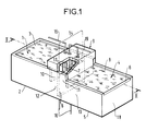
- Figure 1 shows a perspective view of a device according to the invention.
- Figure 2 shows a sectional view along II-II of the same device.
- the device for regulating the flow of a material fluid comprises a receptacle material inlet 1 comprising a bottom wall 2 horizontal, receiving the spilled material at a rate any and containing it according to a filling level 3 and an outlet receptacle 4 comprising a bottom wall 5 horizontal and releasing the material at a rate regulated by a outlet opening 6 which is formed by the upper edge one of its vertical walls, called the discharge wall 18.
- the bottom walls 2, 5 can be at the same level as shown in the figures or at different levels.
- the common wall 6 extends from the bottom walls 2, 5 of the receptacles 1, 4 and has a height less than Fill level 3 of the input receptacle 1. Above of the common wall 6 is arranged an arrangement called bell 9, forming on either side of the common wall 6 a first 10 and a second 11 intermediate receptacles symmetrical with respect to this common wall 6.
- the first intermediate receptacle 10 communicates with the receptacle inlet 1 by a first passage 12 extending along the bottom 2 thereof
- the second intermediate receptacle 11 communicates with the output receptacle 4 by a second passage 13 extending along the bottom 5 thereof and these two intermediate receptacles 10, 11 communicate between them by a third passage 14 extending above the common wall 6.
- these intermediate receptacles 10, 11 are closed and there maintained a gas pressure P by means of a device 15, 16, 19 for maintaining the gas pressure P.
- the pressure maintenance device P can be consisting of a gas supply 15 connected at level le higher of the bell arrangement 9. Alternatively or cumulatively, it may consist of another gas supply 16 connected to said funds 2, 5 on the part and on the other side of the common wall 6. This other variant is particularly suitable for the regulation of fluidized solids this gas also serving as fluidizing gas. By elsewhere, is also connected to the bell 9 a circuit 19 gas leak. The pressure P is therefore adjusted either at regulated gas flow and constant leakage or at flow constant and regulated leakage.
- said third passage 14 is consisting of a plurality of orifices 17 allowing a better operating stability. Indeed in the case fluidized solids, this weir consisting of orifices prevents the possible sudden passage of an agglomerate above from the edge 7 of the common wall.
- the device according to the invention is particularly intended to constitute a regulating valve fluidized solids outlet from a bed boiler fluidized.
- a specific application is the treatment of fluidized solids flowing over the inner wall of the boiler, recovered in the lower part of it and recycled in an exchanger.
- This exchanger must be supplied with a constant flow and the valve according to the invention is arranged in upstream of it.
- the valves commonly used in this field deteriorated very quickly due to thermal operating conditions. It is obvious that the regulation device described is very little sensitive to the effects of temperature.
Landscapes
- Engineering & Computer Science (AREA)
- Power Engineering (AREA)
- Physics & Mathematics (AREA)
- General Physics & Mathematics (AREA)
- Automation & Control Theory (AREA)
- Fluidized-Bed Combustion And Resonant Combustion (AREA)
- Flow Control (AREA)
- Paper (AREA)
- Feeding, Discharge, Calcimining, Fusing, And Gas-Generation Devices (AREA)
- Safety Valves (AREA)
- Pipe Accessories (AREA)
- Control Of Non-Electrical Variables (AREA)
Description
Claims (8)
- Dispositif de régulation du débit d'une matière fluide comportant un réceptacle d'entrée (1) de la matière comprenant une paroi de fond (2), recevant la matière déversée à un débit quelconque et la contenant selon un niveau de remplissage (3) et un réceptacle de sortie (4) comprenant une paroi de fond (5) et libérant la matière à un débit régulé par une ouverture de sortie (6), ces deux réceptacles (1, 4) étant séparés par une paroi commune (6) comportant un bord supérieur (7), dispositif caractérisé en ce que la paroi commune (6) s'étend à partir des parois de fond (2, 5) des réceptacles (1, 4) et a une hauteur inférieure au niveau de remplissage (3) du réceptacle d'entrée (1) et en ce qu'est disposé au-dessus de la paroi commune (6) un agencement dit de cloche (9), formant de part et d'autre de la paroi commune (6) un premier (10) et un second (11) réceptacles intermédiaires, le premier réceptacle intermédiaire (10) communiquant avec le réceptacle d'entrée (1) par un premier passage (12) s'étendant le long du fond (2) de celui-ci, le second réceptacle intermédiaire (11) communiquant avec le réceptacle de sortie (4) par un deuxième passage (13) s'étendant le long du fond (5) de celui-ci, ces deux réceptacles intermédiaires (10, 11) communiquant entre eux par un troisième passage (14) s'étendant au-dessus de la paroi commune (6) où est maintenue une pression de gaz (P), étant, outre ces trois passages (12, 13, 14), fermés et étant reliés à un dispositif (15, 16) de maintien de la pression de gaz (P).
- Dispositif selon la revendication 1, caractérisé en ce que lesdits fonds (2, 5) sont horizontaux et les réceptacles intermédiaires (10, 11) symétriques par rapport à la paroi commune (6).
- Dispositif selon la revendication 2, caractérisé en ce que l'ouverture de sortie (6) est à la même hauteur que le bord supérieur (7) de la paroi commune (6).
- Dispositif selon l'une des revendications précédentes, caractérisé en ce que le dispositif de maintien de la pression de gaz comporte un dispositif d'alimentation en gaz (15, 16) et un dispositif de fuite de gaz (19), l'un de ces dispositifs étant régulé.
- Dispositif selon le revendication 4, caractérisé en ce que le dispositif (15) d'alimentation en gaz est relié au niveau le plus haut de l'agencement de cloche (9).
- Dispositif selon la revendication 4 ou 5, caractérisé en ce que le dispositif (16) d'alimentation en gaz est relié auxdits fonds (2, 5) de part et d'autre de la paroi commune (6).
- Dispositif selon l'une des revendications précédentes, caractérisé en ce que ledit troisième passage (14) est constitué d'une pluralité d'orifices (17).
- Valve de régulation de sortie de solides fluidisés d'une chaudière de lit fluidisé constitué d'un dispositif selon l'une des revendications précédentes.
Applications Claiming Priority (2)
| Application Number | Priority Date | Filing Date | Title |
|---|---|---|---|
| FR9312679 | 1993-10-25 | ||
| FR9312679A FR2711814B1 (fr) | 1993-10-25 | 1993-10-25 | Dispositif de régulation du débit d'une matière fluide. |
Publications (2)
| Publication Number | Publication Date |
|---|---|
| EP0650108A1 EP0650108A1 (fr) | 1995-04-26 |
| EP0650108B1 true EP0650108B1 (fr) | 1998-04-22 |
Family
ID=9452166
Family Applications (1)
| Application Number | Title | Priority Date | Filing Date |
|---|---|---|---|
| EP94402392A Expired - Lifetime EP0650108B1 (fr) | 1993-10-25 | 1994-10-24 | Dispositif de régulation du débit d'une matière fluide |
Country Status (9)
| Country | Link |
|---|---|
| US (1) | US5540257A (fr) |
| EP (1) | EP0650108B1 (fr) |
| CN (1) | CN1076492C (fr) |
| AT (1) | ATE165458T1 (fr) |
| DE (1) | DE69409751T2 (fr) |
| ES (1) | ES2117229T3 (fr) |
| FI (1) | FI111997B (fr) |
| FR (1) | FR2711814B1 (fr) |
| RU (1) | RU2137174C1 (fr) |
Families Citing this family (9)
| Publication number | Priority date | Publication date | Assignee | Title |
|---|---|---|---|---|
| US6474356B2 (en) * | 1997-02-25 | 2002-11-05 | Gertjan Roelof Bouwkamp | Device for controlling a liquid flow |
| US5913981A (en) | 1998-03-05 | 1999-06-22 | Micron Technology, Inc. | Method of rinsing and drying semiconductor wafers in a chamber with a moveable side wall |
| DE102004025814A1 (de) | 2004-05-24 | 2006-01-05 | Hans Sasserath & Co. Kg | Druckminderer |
| CN102966767A (zh) * | 2012-11-12 | 2013-03-13 | 叶晓丰 | 一种流体通断方法及流体通断装置 |
| CN102963506B (zh) * | 2012-11-12 | 2015-02-25 | 叶晓丰 | 一种截流装置 |
| AT517129B1 (de) * | 2015-04-23 | 2017-09-15 | Bernhard Wett Dr | Verfahren zum abzug von wasser aus einem becken |
| US11192734B2 (en) | 2018-03-27 | 2021-12-07 | Mac Trailer Manufacturing, Inc. | Tank having an air piping system and method of loading and unloading the same |
| US10919431B2 (en) | 2018-03-27 | 2021-02-16 | Mac Trailer Manufacturing, Inc. | Dry bulk tank |
| CN113233702B (zh) * | 2021-05-14 | 2022-09-27 | 秦皇岛同力达环保能源股份有限公司 | 一种合并式生活污水处理方法及系统 |
Family Cites Families (9)
| Publication number | Priority date | Publication date | Assignee | Title |
|---|---|---|---|---|
| US37617A (en) * | 1863-02-10 | Improvement in sewing-machines | ||
| US3035888A (en) * | 1960-10-31 | 1962-05-22 | Universal Oil Prod Co | Process and apparatus for obtaining a constant head of liquid |
| US3424186A (en) * | 1966-09-26 | 1969-01-28 | Robert J Sparks | Circulating device |
| DD206309A3 (de) * | 1981-07-17 | 1984-01-18 | Kretschmer Horst | Verfahren zur regelung von massenstroemen |
| SU1124260A1 (ru) * | 1983-07-08 | 1984-11-15 | Предприятие П/Я А-1094 | Устройство дл регулировани расхода жидкости |
| SU1269103A1 (ru) * | 1984-12-17 | 1986-11-07 | Предприятие П/Я А-1094 | Устройство дл регулировани расхода жидкости |
| CH666747A5 (de) * | 1985-06-03 | 1988-08-15 | Landis & Gyr Ag | Vorrichtung zur regelung der durchflussmenge. |
| US5037617A (en) * | 1990-01-04 | 1991-08-06 | Stone & Webster Engineering Corporation | Apparatus for the return of particulate solids through a cyclone separator to a vessel |
| US5282487A (en) * | 1992-10-19 | 1994-02-01 | Timpany Peter L | Flow control system |
-
1993
- 1993-10-25 FR FR9312679A patent/FR2711814B1/fr not_active Expired - Fee Related
-
1994
- 1994-10-21 FI FI944964A patent/FI111997B/fi active
- 1994-10-24 EP EP94402392A patent/EP0650108B1/fr not_active Expired - Lifetime
- 1994-10-24 DE DE69409751T patent/DE69409751T2/de not_active Expired - Lifetime
- 1994-10-24 RU RU94037961A patent/RU2137174C1/ru active
- 1994-10-24 AT AT94402392T patent/ATE165458T1/de not_active IP Right Cessation
- 1994-10-24 ES ES94402392T patent/ES2117229T3/es not_active Expired - Lifetime
- 1994-10-24 US US08/327,642 patent/US5540257A/en not_active Expired - Lifetime
- 1994-10-25 CN CN94117736A patent/CN1076492C/zh not_active Expired - Lifetime
Also Published As
| Publication number | Publication date |
|---|---|
| DE69409751T2 (de) | 1998-09-17 |
| FI111997B (fi) | 2003-10-15 |
| DE69409751D1 (de) | 1998-05-28 |
| FR2711814A1 (fr) | 1995-05-05 |
| ES2117229T3 (es) | 1998-08-01 |
| US5540257A (en) | 1996-07-30 |
| FR2711814B1 (fr) | 1995-12-29 |
| ATE165458T1 (de) | 1998-05-15 |
| CN1076492C (zh) | 2001-12-19 |
| RU2137174C1 (ru) | 1999-09-10 |
| EP0650108A1 (fr) | 1995-04-26 |
| FI944964A0 (fi) | 1994-10-21 |
| CN1111741A (zh) | 1995-11-15 |
| FI944964L (fi) | 1995-04-26 |
| RU94037961A (ru) | 1996-08-27 |
Similar Documents
| Publication | Publication Date | Title |
|---|---|---|
| EP0650108B1 (fr) | Dispositif de régulation du débit d'une matière fluide | |
| FR2736339A1 (fr) | Bec de remplissage a ecoulement laminaire | |
| CA2114602A1 (fr) | Clapet de retenue | |
| FR2720116A1 (fr) | Circuit de distribution de carburant à organe de ventilation. | |
| US269886A (en) | semple | |
| FR2792387A1 (fr) | Raccord a soupapes pour un recipient sous pression | |
| FR2530289A1 (fr) | Circuit de refroidissement pour moteurs a combustion inter ne notamment par une pompe de circulation | |
| US6923872B2 (en) | Arrangement and method for cleaning fine solid particles from a continuously flowing liquid suspension | |
| EP0169135A1 (fr) | Vanne pour répartition pneumatique de matière fluidisable | |
| FR2576806A1 (fr) | Bol centrifuge pour clarifier et separer des fluides a centrifuger | |
| FR2644221A3 (fr) | Soupape de commande | |
| FR2612425A1 (fr) | Dispositif de sortie dans un separateur centrifuge | |
| FR2482640A1 (fr) | Dispositif pour le prelevement de liquides dans des bassins ou similaires | |
| NL7905792A (nl) | Regelklep. | |
| EP0233118B1 (fr) | Clapet de purge multifonctions | |
| FR2596786A1 (fr) | Dispositif de vidage d'un reservoir de liquide, notamment dispositif de chasse d'eau pour cuvette de w.c. | |
| US682480A (en) | Apparatus for filling or emptying reservoirs automatically. | |
| FR2806928A1 (fr) | Reacteur modulaire automatise pour la synthese chimique | |
| FR3094808A1 (fr) | Cartouche thermostatique | |
| US658794A (en) | Hydrocarbon-burner and pressure device therefor. | |
| FR1464760A (fr) | Robinet | |
| US734378A (en) | Means for controlling the flow of liquids from or to chambers, pipes, or other receptacles. | |
| GB2270361A (en) | Valve float with sealing hull and weighted keel | |
| US535415A (en) | Ice-discharging apparatus | |
| FR2493176A1 (fr) | Dispositif pour melanger un premier fluide a un second fluide vecteur |
Legal Events
| Date | Code | Title | Description |
|---|---|---|---|
| PUAI | Public reference made under article 153(3) epc to a published international application that has entered the european phase |
Free format text: ORIGINAL CODE: 0009012 |
|
| AK | Designated contracting states |
Kind code of ref document: A1 Designated state(s): AT BE DE ES FR GB GR SE |
|
| 17P | Request for examination filed |
Effective date: 19950819 |
|
| GRAG | Despatch of communication of intention to grant |
Free format text: ORIGINAL CODE: EPIDOS AGRA |
|
| GRAG | Despatch of communication of intention to grant |
Free format text: ORIGINAL CODE: EPIDOS AGRA |
|
| GRAH | Despatch of communication of intention to grant a patent |
Free format text: ORIGINAL CODE: EPIDOS IGRA |
|
| 17Q | First examination report despatched |
Effective date: 19970925 |
|
| GRAH | Despatch of communication of intention to grant a patent |
Free format text: ORIGINAL CODE: EPIDOS IGRA |
|
| GRAA | (expected) grant |
Free format text: ORIGINAL CODE: 0009210 |
|
| AK | Designated contracting states |
Kind code of ref document: B1 Designated state(s): AT BE DE ES FR GB GR SE |
|
| REF | Corresponds to: |
Ref document number: 165458 Country of ref document: AT Date of ref document: 19980515 Kind code of ref document: T |
|
| REF | Corresponds to: |
Ref document number: 69409751 Country of ref document: DE Date of ref document: 19980528 |
|
| GBT | Gb: translation of ep patent filed (gb section 77(6)(a)/1977) |
Effective date: 19980622 |
|
| REG | Reference to a national code |
Ref country code: ES Ref legal event code: FG2A Ref document number: 2117229 Country of ref document: ES Kind code of ref document: T3 |
|
| PLBE | No opposition filed within time limit |
Free format text: ORIGINAL CODE: 0009261 |
|
| STAA | Information on the status of an ep patent application or granted ep patent |
Free format text: STATUS: NO OPPOSITION FILED WITHIN TIME LIMIT |
|
| 26N | No opposition filed | ||
| PGFP | Annual fee paid to national office [announced via postgrant information from national office to epo] |
Ref country code: GB Payment date: 20010914 Year of fee payment: 8 |
|
| PGFP | Annual fee paid to national office [announced via postgrant information from national office to epo] |
Ref country code: AT Payment date: 20010925 Year of fee payment: 8 |
|
| PGFP | Annual fee paid to national office [announced via postgrant information from national office to epo] |
Ref country code: GR Payment date: 20010927 Year of fee payment: 8 |
|
| PGFP | Annual fee paid to national office [announced via postgrant information from national office to epo] |
Ref country code: SE Payment date: 20011001 Year of fee payment: 8 |
|
| PGFP | Annual fee paid to national office [announced via postgrant information from national office to epo] |
Ref country code: BE Payment date: 20011011 Year of fee payment: 8 |
|
| PGFP | Annual fee paid to national office [announced via postgrant information from national office to epo] |
Ref country code: ES Payment date: 20011024 Year of fee payment: 8 |
|
| REG | Reference to a national code |
Ref country code: GB Ref legal event code: IF02 |
|
| PG25 | Lapsed in a contracting state [announced via postgrant information from national office to epo] |
Ref country code: GB Free format text: LAPSE BECAUSE OF NON-PAYMENT OF DUE FEES Effective date: 20021024 Ref country code: AT Free format text: LAPSE BECAUSE OF NON-PAYMENT OF DUE FEES Effective date: 20021024 |
|
| PG25 | Lapsed in a contracting state [announced via postgrant information from national office to epo] |
Ref country code: SE Free format text: LAPSE BECAUSE OF NON-PAYMENT OF DUE FEES Effective date: 20021025 Ref country code: ES Free format text: LAPSE BECAUSE OF NON-PAYMENT OF DUE FEES Effective date: 20021025 |
|
| PG25 | Lapsed in a contracting state [announced via postgrant information from national office to epo] |
Ref country code: BE Free format text: LAPSE BECAUSE OF NON-PAYMENT OF DUE FEES Effective date: 20021031 |
|
| BERE | Be: lapsed |
Owner name: *GEC ALSTHOM STEIN INDUSTRIE Effective date: 20021031 |
|
| PG25 | Lapsed in a contracting state [announced via postgrant information from national office to epo] |
Ref country code: GR Free format text: LAPSE BECAUSE OF NON-PAYMENT OF DUE FEES Effective date: 20030506 |
|
| EUG | Se: european patent has lapsed | ||
| GBPC | Gb: european patent ceased through non-payment of renewal fee |
Effective date: 20021024 |
|
| REG | Reference to a national code |
Ref country code: ES Ref legal event code: FD2A Effective date: 20031112 |
|
| REG | Reference to a national code |
Ref country code: FR Ref legal event code: ST Effective date: 20080630 |
|
| PGFP | Annual fee paid to national office [announced via postgrant information from national office to epo] |
Ref country code: FR Payment date: 20061016 Year of fee payment: 13 |
|
| PG25 | Lapsed in a contracting state [announced via postgrant information from national office to epo] |
Ref country code: FR Free format text: LAPSE BECAUSE OF NON-PAYMENT OF DUE FEES Effective date: 20071031 |
|
| REG | Reference to a national code |
Ref country code: DE Ref legal event code: R082 Ref document number: 69409751 Country of ref document: DE Representative=s name: DREISS PATENTANWAELTE PARTG MBB, DE Effective date: 20110908 Ref country code: DE Ref legal event code: R082 Ref document number: 69409751 Country of ref document: DE Representative=s name: DREISS PATENTANWAELTE, DE Effective date: 20110908 Ref country code: DE Ref legal event code: R081 Ref document number: 69409751 Country of ref document: DE Owner name: ALSTOM TECHNOLOGY LTD., CH Free format text: FORMER OWNER: GEC ALSTHOM STEIN INDUSTRIE, VELIZY-VILLACOUBLAY, FR Effective date: 20110908 Ref country code: DE Ref legal event code: R081 Ref document number: 69409751 Country of ref document: DE Owner name: ALSTOM POWER SYSTEMS SA, FR Free format text: FORMER OWNER: GEC ALSTHOM STEIN INDUSTRIE, VELIZY-VILLACOUBLAY, FR Effective date: 20110908 |
|
| REG | Reference to a national code |
Ref country code: DE Ref legal event code: R082 Ref document number: 69409751 Country of ref document: DE Representative=s name: DREISS PATENTANWAELTE, DE |
|
| REG | Reference to a national code |
Ref country code: DE Ref legal event code: R082 Ref document number: 69409751 Country of ref document: DE Representative=s name: DREISS PATENTANWAELTE PARTG MBB, DE Effective date: 20120123 Ref country code: DE Ref legal event code: R082 Ref document number: 69409751 Country of ref document: DE Representative=s name: DREISS PATENTANWAELTE, DE Effective date: 20120123 Ref country code: DE Ref legal event code: R081 Ref document number: 69409751 Country of ref document: DE Owner name: ALSTOM TECHNOLOGY LTD., CH Free format text: FORMER OWNER: ALSTOM POWER BOILERS, MEUDON LA FORET, FR Effective date: 20120123 |
|
| REG | Reference to a national code |
Ref country code: DE Ref legal event code: R082 Ref document number: 69409751 Country of ref document: DE Representative=s name: DREISS PATENTANWAELTE, DE |
|
| REG | Reference to a national code |
Ref country code: DE Ref legal event code: R082 Ref document number: 69409751 Country of ref document: DE Representative=s name: DREISS PATENTANWAELTE PARTG MBB, DE Effective date: 20120320 Ref country code: DE Ref legal event code: R081 Ref document number: 69409751 Country of ref document: DE Owner name: ALSTOM TECHNOLOGY LTD., CH Free format text: FORMER OWNER: ALSTOM POWER SYSTEMS SA, LAVALLOIS PERRET CEDEX, FR Effective date: 20120320 |
|
| PGFP | Annual fee paid to national office [announced via postgrant information from national office to epo] |
Ref country code: DE Payment date: 20131031 Year of fee payment: 20 |
|
| REG | Reference to a national code |
Ref country code: DE Ref legal event code: R071 Ref document number: 69409751 Country of ref document: DE |