EP0650140A2 - Verringerung der Anzahl gedruckter Punkte in einer Pixelanordnung - Google Patents
Verringerung der Anzahl gedruckter Punkte in einer Pixelanordnung Download PDFInfo
- Publication number
- EP0650140A2 EP0650140A2 EP94307373A EP94307373A EP0650140A2 EP 0650140 A2 EP0650140 A2 EP 0650140A2 EP 94307373 A EP94307373 A EP 94307373A EP 94307373 A EP94307373 A EP 94307373A EP 0650140 A2 EP0650140 A2 EP 0650140A2
- Authority
- EP
- European Patent Office
- Prior art keywords
- pixel
- depletion
- plane
- pixels
- image
- Prior art date
- Legal status (The legal status is an assumption and is not a legal conclusion. Google has not performed a legal analysis and makes no representation as to the accuracy of the status listed.)
- Granted
Links
Images


Classifications
-
- G—PHYSICS
- G06—COMPUTING OR CALCULATING; COUNTING
- G06K—GRAPHICAL DATA READING; PRESENTATION OF DATA; RECORD CARRIERS; HANDLING RECORD CARRIERS
- G06K15/00—Arrangements for producing a permanent visual presentation of the output data, e.g. computer output printers
- G06K15/02—Arrangements for producing a permanent visual presentation of the output data, e.g. computer output printers using printers
- G06K15/10—Arrangements for producing a permanent visual presentation of the output data, e.g. computer output printers using printers by matrix printers
- G06K15/102—Arrangements for producing a permanent visual presentation of the output data, e.g. computer output printers using printers by matrix printers using ink jet print heads
-
- G—PHYSICS
- G06—COMPUTING OR CALCULATING; COUNTING
- G06K—GRAPHICAL DATA READING; PRESENTATION OF DATA; RECORD CARRIERS; HANDLING RECORD CARRIERS
- G06K15/00—Arrangements for producing a permanent visual presentation of the output data, e.g. computer output printers
- G06K15/02—Arrangements for producing a permanent visual presentation of the output data, e.g. computer output printers using printers
-
- G—PHYSICS
- G06—COMPUTING OR CALCULATING; COUNTING
- G06K—GRAPHICAL DATA READING; PRESENTATION OF DATA; RECORD CARRIERS; HANDLING RECORD CARRIERS
- G06K15/00—Arrangements for producing a permanent visual presentation of the output data, e.g. computer output printers
- G06K15/02—Arrangements for producing a permanent visual presentation of the output data, e.g. computer output printers using printers
- G06K15/10—Arrangements for producing a permanent visual presentation of the output data, e.g. computer output printers using printers by matrix printers
Definitions
- the present invention relates to the field of pixel-array printing. More specifically, the present invention pertains to a method for depleting dots in high-density print regions in the ink-jet implementation of pixel-array printing.
- pixel-array refers to a (usually large) two-dimensional array of uniformly spaced and sized cells called pixels (picture elements). By "turning on” certain pixels with ink, light, etc., an image of text and pictures may be formed on the array. The intrinsic binary nature of this image becomes less obvious and the perceived image quality improves as the number of pixels per unit area increases.
- pixel-array printing certain areas on the print media may receive a relatively large amount of ink because of the density of the printed image in those areas.
- ink-jet technology a form of pixel-array printing, drops of ink are expelled from one or more nozzles in a printhead onto a print surface such as paper. Usually one drop produces a single pixel or dot. Sometimes the amount of ink is excessive due to expelling larger ink drops than desired from the printhead. This may be caused by manufacturing tolerances, high temperatures, or other reasons. When this happens, these dense areas can cause problems in the quality of printing and the handling of the media.
- the ink may not dry quickly enough. As a result, the still-wet ink may blot onto the preceding or following page in the output tray. The following page may rub against the wet ink and smear the image. When the user picks up the page, the ink may smear on the user's hands or clothes, also smearing the image.
- ink may be wasted, as the enlarged drops overlap each other.
- An equally dense image may be achieved with less ink, and with less drying problems.
- ink in high-density areas may wick to lower-density areas, degrading the image quality.
- Inks may be formulated to be absorbed quickly into the paper. However, these inks also tend to wick along the surface fibers as well, thus degrading edges in the image.
- a printhead which ejects less ink - that is, a lower "drop volume" printhead - may also be used.
- printheads which have a lower drop volume tend to magnify the variations caused by manufacturing or operating tolerances. These tolerances can be decreased to minimize the artifacts, but this causes additional expense in materials and manufacturing.
- a heater could be used to control the environment around the printing process to ensure that the ink dries quickly enough. However, the heater and supporting hardware would add to the cost of the printer.
- the printer could detect when high densities of ink have been printed on a page, and pause to allow the ink to dry before ejecting the page to the output tray. Such pauses would decrease the throughput of the printer.
- a repeating 8 x 8 depletion mask may be used which arbitrarily depletes those pixels blocked by the mask.
- the arbitrariness of the depletion tends to degrade images and edges of text.
- the 8 x 8 size is likely to cause artifacts when applied to halftoned data. These artifacts occur because the halftoning is achieved through application of a "dither cell" whose dimensions are typically 8 x 8 or other numbers having a common factor with 8. Interaction between the dither cell and the depletion mask can cause periodic artifacts which are highly visible in the printed image.
- pixels may be randomly depleted over the image until the desired amount of depletion has occurred. But this method also tends to degrade images and edges of text. It also allows pixels adjacent to each other to be depleted, causing visible spaces between pixels.
- the present invention allows high-density print regions to be depleted without significantly degrading print quality. Applying the methodology of the invention to a printer requires only inexpensive modifications.
- the invention includes a method which operates on images comprised of pixels.
- a depletion table is generated.
- the depletion table marks those pixels which are candidates for depletion.
- a two-step process is used. First, the depletion table is checked to determine if the pixel is a candidate for depletion. Second, the adjacent pixels are checked to determine if the candidate is an edge pixel. If the pixel is a candidate for depletion and is not an edge pixel, it is depleted.
- Pixels which define an edge of the printed image are not depleted, even when they are candidates for depletion. This preserves the sharpness and attendant quality of the image. This is especially important for alphanumeric text. Also, in areas of low density, such as found in halftone graphics, this approach maintains greyscales and image gradations.
- the depletion table prefferably has dimensions which have no common factors with the dimensions of an ordered-dither cell used in halftoning the image data. Dimensions of 7 x 7 are preferable for the depletion table.
- a particular pixel is a candidate for depletion if the depletion table, when mapped onto the image data, has a corresponding entry marking the pixel as such.
- the set of depletion tables mapped over the entire image may be called a "depletion plane.”
- a preferred method of generating a depletion plane uses the modulo function to "tile" the depletion table - that is, to repeat it periodically in both dimensions - across the image data.
- the modulo function uses the position of the pixel in the image and the dimensions of the depletion table.
- a particular pixel is determined not to be an edge pixel if the four pixels adjacent to it are "on” (that is, are to be printed). As a preferred enhancement, if only one of the adjacent pixels is "off”, then as long as that one "off" pixel is surrounded by “on” pixels, the particular pixel is determined to not be an edge pixel.
- FIG. 1 shows an overall flow diagram of a depletion method according to the present invention
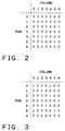
- FIG. 2 shows a 7 x 7 depletion table, for use in the method of FIG. 1, having 10 percent depletion.
- FIG. 3 shows a 7 x 7 depletion table, for use in the method of FIG. 1, having 20 percent depletion.
- FIG. 4 shows a 7 x 7 depletion table, for use in the method of FIG. 1, having 31 percent depletion.
- FIG. 5 shows a 7 x 7 depletion table, for use in the method of FIG. 1, having 49 percent depletion.
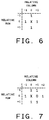
- FIG. 6 shows a prospective pixel to be depleted in relation to four adjacent pixels.
- FIG. 7 shows a prospective pixel to be depleted in relation to four adjacent pixels and three additional pixels.
- the present invention provides a method for depleting which may be used on the entire image. It will not deplete those areas which should not be depleted, in particular sharp edges of the image, such as those of alphanumeric text.
- the depletion table is a rectangular array of binary flags which can be mapped onto all pixels of the undepleted image.
- a "TRUE" flag designates that the corresponding pixel is a potential candidate for depletion.
- the percentage of "TRUE” flags in the depletion table can be increased or decreased, depending on the characteristics of the printer and the desired output results. For example, an otherwise too-large percentage may be chosen to conserve ink and provide an economy print mode.
- the percentage of "TRUE” flags is an upper bound on the percentage of pixels ultimately depleted since, as will be explained shortly, some candidates for depletion will be spared when it is determined that they are also "edge" pixels.
- the "TRUE” flags should be arranged to be spaced apart.
- the spacing should take into consideration that the table will be tiled across the undepleted image.
- the left and right edges of the table are effectively adjacent, as are the top and bottom edges.
- the undepleted data upon which the method of the present invention operates may be text, line art, or half-toned images.
- Digital half-toned images are commonly generated using a two-dimensional ordered-dither cell. If the dimensions of the depletion table have common factors with those of the ordered-dither cell, then the resulting image can be noticeably degraded.
- the height and width of the depletion table preferably have no common factors with the height and width, respectively, of any ordered-dither cell which has been used to generate the undepleted data.
- a depletion table which is 7 x 7 works well. Although there is no standard size for an ordered dither cell, currently observed sizes are 8 x 8, 16 x 16, 6 x 6, 10 x 10, and 12 x 12. Ordered dither cells are unlikely to be 7 x 7 or 14 x 14 because these are close in size to 8 x 8 and 16 x 16, which dimensions, since they match the size of one byte or two bytes, are easier and faster to work with for most halftoning implementations.
- depletion table's width and height be equal.
- FIGS. 2 through 5 show exemplary 7 x 7 depletion tables.
- the depletion table of FIG. 2 has five "TRUE” flags (designated by the number “1") resulting in a potential depletion of 5/49 or approximately ten percent.
- the depletion tables of FIGS. 3, 4, and 5 have 10, 15, and 24 "TRUE” flags respectively, resulting in potential depletions of approximately 20 percent, 31 percent, and 49 percent.
- a pixel is chosen for examination (step 11).
- the depletion table is then used to determine whether this pixel is a candidate for depletion (step 12).
- the undepleted image may be represented as a two-dimensional array Image[row,column].
- the pixel at the upper-left corner of the image is represented as Image[0,0] with columns increasing to the right and rows increasing to the bottom of the image.
- the depletion table may be described as an array Table[row,column] whose dimensions match the size of the table.
- the modulo function tiles the depletion table on the image.
- an edge test is applied: the current pixel's adjacent "neighbors" are examined to determine if the pixel is an edge pixel (step 14).
- a pixel denoted by "X" at the relative location (0,0) has four immediately adjacent pixels: Image(-1,0), Image(0,+1), Image(+1,0), and Image(0,-1).
- the parentheses in the foregoing expressions denote relative locations; brackets are used for absolute locations.
- a pixel is not an edge pixel if each of these four adjacent pixels is on.
- the alternative edge test can be carried out as follows. First, the pixel being examined is subjected to the test of FIG. 6. If it is thereby determined to be a depletion candidate, the test is over and the next pixel is examined. However, if it is rejected as a candidate by the test of FIG. 6, then the test illustrated in FIG. 7 is applied. First, it must be determined that only one of the four neighbors is off, and that it is (in this illustration) the east neighbor. This is shown in FIG. 7 as Image(0,+1), or the pixel to the right of Image(0,0), the test pixel X. The three neighbors of Image(0,+1) are then examined: Image(-1,+1), Image(0,+2), and Image(+1,+1). If they are on, pixel X thereby becomes a depletion candidate. In Fig. 7, the three neighbors of Image(0,+1) are on, and so pixel X is a depletion candidate.
- the current pixel is a depletion candidate and not an edge pixel (block 16)
- the pixel is depleted in block 18. That is, no ink dot is applied at that pixel location.
- a check is made to see whether all pixels have been processed (step 19). If not, a new pixel is chosen for examination (step 20) and the method is repeated until all pixels are processed.
- a microprocessor an array processor, or some special-purpose hardware is available, then more than one pixel at a time may be processed through a large-scale or "batch" processing mode of the invention.
- the following explanation pertains to batch processing the input image plane, using the first edge-detecting method (illustrated in Fig. 6).
- a modified image plane composed of non-edge pixels is generated:
- the input plane is shifted by one pixel in each of four directions (left, right, up, down), thereby generating four shifted planes.
- the logical AND of these four planes is an image plane with only non-edge pixels retained.
- a depletion plane is generated by tiling the depletion table both horizontally and vertically a sufficient number of times to cover all pixel locations in the image plane. (Tiles which extend beyond the edges of the image plane may be truncated).
- a pixel-depletion locator plane is formed by generating the logical AND of the non-edge pixel plane and the depletion plane.
- the pixel-depletion locator plane is logically inverted and then logically ANDed with the input image plane.
- the resultant is an image plane with appropriate pixels depleted in accordance with the teachings of this invention.
- the several planes can be treated as two-dimensional arrays and processed n bits at a time, where n is the bit width of the microprocessor, typically 8, 16, or 32.
- the modified image plane may be formed by ANDing four n -bit words, the data of each obtained by shifting the corresponding image data in one of the four directions. The result becomes the first n -bit word of the modified plane. The process is repeated until all the data of the modified plane is generated.
- the depletion plane contains the repeated data of the depletion table, it is highly redundant. Therefore, it would be wasteful of memory to store the whole plane, only to retrieve and process n bits at a time. There are more efficient ways of producing the same result.
Landscapes
- Engineering & Computer Science (AREA)
- Physics & Mathematics (AREA)
- General Engineering & Computer Science (AREA)
- General Physics & Mathematics (AREA)
- Theoretical Computer Science (AREA)
- Mathematical Physics (AREA)
- Image Processing (AREA)
- Facsimile Image Signal Circuits (AREA)
- Dot-Matrix Printers And Others (AREA)
- Fax Reproducing Arrangements (AREA)
Applications Claiming Priority (2)
| Application Number | Priority Date | Filing Date | Title |
|---|---|---|---|
| US13867893A | 1993-10-18 | 1993-10-18 | |
| US138678 | 2002-05-03 |
Publications (3)
| Publication Number | Publication Date |
|---|---|
| EP0650140A2 true EP0650140A2 (de) | 1995-04-26 |
| EP0650140A3 EP0650140A3 (de) | 1995-07-12 |
| EP0650140B1 EP0650140B1 (de) | 1999-08-25 |
Family
ID=22483134
Family Applications (1)
| Application Number | Title | Priority Date | Filing Date |
|---|---|---|---|
| EP94307373A Expired - Lifetime EP0650140B1 (de) | 1993-10-18 | 1994-10-07 | Verringerung der Anzahl gedruckter Punkte in einer Pixelanordnung |
Country Status (4)
| Country | Link |
|---|---|
| US (1) | US5706414A (de) |
| EP (1) | EP0650140B1 (de) |
| JP (1) | JPH07236057A (de) |
| DE (1) | DE69420225T2 (de) |
Cited By (1)
| Publication number | Priority date | Publication date | Assignee | Title |
|---|---|---|---|---|
| EP0689159A3 (de) * | 1994-06-23 | 1996-01-10 | Seiko Epson Corp |
Families Citing this family (28)
| Publication number | Priority date | Publication date | Assignee | Title |
|---|---|---|---|---|
| JPH07107280A (ja) * | 1993-10-06 | 1995-04-21 | Matsushita Electric Ind Co Ltd | 画像形成装置 |
| JP3387657B2 (ja) * | 1994-10-19 | 2003-03-17 | キヤノン株式会社 | 記録装置 |
| US6299284B1 (en) * | 1996-10-21 | 2001-10-09 | Hewlett-Packard Company | Color inkjet depletion technique for over-sized ink drops to achieve high resolution X/Y axes addressability |
| US6296343B1 (en) * | 1996-10-21 | 2001-10-02 | Hewlett-Packard Company | Edge enhancement depletion technique for over-sized ink drops to achieve high resolution X/Y axes addressability in inkjet printing |
| US6019454A (en) * | 1997-03-04 | 2000-02-01 | Hewlett-Packard Company | Multipass inkjet printmodes with randomized dot placement, to minimize patterning and liquid loading |
| US6049393A (en) * | 1997-11-19 | 2000-04-11 | Tektronix, Inc. | Method for enhancing resolution in a printed image |
| US6318854B1 (en) | 1998-09-29 | 2001-11-20 | Hewlett-Packard Company | Inkjet printing media handling system with advancing guide shim |
| US6508529B2 (en) | 1998-09-29 | 2003-01-21 | Hewlett-Packard Company | Inkjet printing media handling system and method for reducing cockle growth |
| US6389167B1 (en) * | 1998-10-30 | 2002-05-14 | Hewlett-Packard Company | Multi-level pixel density reduction for printers |
| JP3775935B2 (ja) * | 1999-01-19 | 2006-05-17 | 武藤工業株式会社 | インクジェットプリンタにおけるドット削除方法 |
| US6154233A (en) * | 1999-04-19 | 2000-11-28 | Lexmark International, Inc. | System and method for separating raster data for printing |
| US7110140B1 (en) * | 1999-08-05 | 2006-09-19 | Xerox Corporation | Methods and systems for undercolor reduction |
| US6650793B1 (en) | 2000-03-31 | 2003-11-18 | Hewlett-Packard Development Company, Lp. | Multiple data manipulation algorithms for text quality enhancement |
| US6804417B1 (en) | 2000-03-31 | 2004-10-12 | Hewlett-Packard Development Company, L.P. | Pixel depletion technique |
| US6721065B1 (en) | 2000-06-01 | 2004-04-13 | Lucent Technologies Inc. | Method and apparatus for printing images |
| US6464334B2 (en) * | 2001-01-08 | 2002-10-15 | Hewlett-Packard Company | Method for improving the quality of printing processes involving black pixel depletion |
| US7046389B2 (en) * | 2001-04-04 | 2006-05-16 | Hewlett-Packard Development Company, L.P. | Variable density under/overprinting maps for improving print quality |
| US7016082B2 (en) * | 2001-07-05 | 2006-03-21 | Kodak Polychrome Graphics, Llc | Halftone dot thinning |
| JP4678468B2 (ja) * | 2001-09-13 | 2011-04-27 | コニカミノルタホールディングス株式会社 | インクジェット式プリンタ用の画像データ処理方法 |
| US7116821B2 (en) * | 2002-03-25 | 2006-10-03 | Lexmark International, Inc. | Color trapping for an image forming apparatus |
| WO2004010684A1 (en) * | 2002-07-24 | 2004-01-29 | Kodak Polychrome Graphics | Halftone dot thinning |
| US7088465B2 (en) * | 2002-08-22 | 2006-08-08 | International Business Machines Corporation | Printing more or less of a web page |
| US7330288B2 (en) * | 2003-03-31 | 2008-02-12 | Eastman Kodak Company | Post RIP image rendering in a MICR electrographic printer to improve readability |
| WO2006018987A1 (ja) * | 2004-08-18 | 2006-02-23 | Konica Minolta Medical & Graphic, Inc. | 画像記録方法及び画像記録装置 |
| US9041978B2 (en) * | 2007-11-24 | 2015-05-26 | Hewlett-Packard Development Company, L.P. | Selecting printing masks optimized for line features and area fill features of image data |
| US8172152B2 (en) * | 2009-03-20 | 2012-05-08 | Delphax Technologies, Inc. | Method for inkjet printing of E13B magnetic ink character recognition characters and substrate having such characters printed thereon |
| US8764151B2 (en) * | 2010-06-21 | 2014-07-01 | Xerox Corporation | System and method for preserving edges while enabling inkjet correction within an interior of an image |
| DE102019101578B3 (de) * | 2019-01-23 | 2020-02-27 | Koenig & Bauer Ag | Verfahren zum Erzeugen eines Druckproduktes mit mindestens einem Non-Impact-Druckaggregat |
Family Cites Families (14)
| Publication number | Priority date | Publication date | Assignee | Title |
|---|---|---|---|---|
| JPS6115460A (ja) * | 1984-06-29 | 1986-01-23 | Minolta Camera Co Ltd | サ−マルラインヘツドの駆動方法 |
| JPS63247039A (ja) * | 1987-04-03 | 1988-10-13 | Nec Corp | 二値画像情報のスクリ−ン化方式 |
| DE69033579T2 (de) * | 1989-04-10 | 2001-03-08 | Canon K.K., Tokio/Tokyo | Bildverkleinerungsgerät und Verfahren |
| DE3925913A1 (de) * | 1989-08-04 | 1991-02-07 | Siemens Ag | Verfahren zum ansteuern von druckelementen |
| DE69027659T2 (de) * | 1989-12-26 | 1996-12-05 | New Oji Paper Co | Punktdrucker |
| JPH04220764A (ja) * | 1990-03-13 | 1992-08-11 | Hewlett Packard Co <Hp> | 文字フォント圧縮方法および装置 |
| US5329616A (en) * | 1990-08-16 | 1994-07-12 | Canon Kabushiki Kaisha | Compressed image stores for high resolution computer graphics |
| US5353387A (en) * | 1990-09-10 | 1994-10-04 | Mannesmann Aktiengesellschaft | Process for reducing the quantity of ink applied to recording substrates by ink printing devices to prevent image degradation |
| US5270728A (en) * | 1991-04-17 | 1993-12-14 | Hewlett-Packard Company | Raster imaging device speed-resolution product multiplying method and resulting pixel image data structure |
| JPH05177873A (ja) * | 1991-12-26 | 1993-07-20 | Nec Corp | プリンタ装置 |
| US5216451A (en) * | 1992-12-27 | 1993-06-01 | Xerox Corporation | Surface ripple wave diffusion in apertured free ink surface level controllers for acoustic ink printers |
| US5426010A (en) * | 1993-02-26 | 1995-06-20 | Oxford Computer, Inc. | Ultra high resolution printing method |
| US5483625A (en) * | 1993-04-26 | 1996-01-09 | Hewlett-Packard Company | Method and apparatus for adjusting density in digital images |
| US5422664A (en) * | 1993-06-25 | 1995-06-06 | Xerox Corporation | Method and apparatus for maintaining constant drop size mass in thermal ink jet printers |
-
1994
- 1994-10-07 DE DE69420225T patent/DE69420225T2/de not_active Expired - Lifetime
- 1994-10-07 EP EP94307373A patent/EP0650140B1/de not_active Expired - Lifetime
- 1994-10-18 JP JP6278441A patent/JPH07236057A/ja active Pending
-
1996
- 1996-10-10 US US08/728,419 patent/US5706414A/en not_active Expired - Lifetime
Cited By (2)
| Publication number | Priority date | Publication date | Assignee | Title |
|---|---|---|---|---|
| EP0689159A3 (de) * | 1994-06-23 | 1996-01-10 | Seiko Epson Corp | |
| US5699172A (en) * | 1994-06-23 | 1997-12-16 | Seiko Epson Corporation | Image forming apparatus and method having a toner and ink saving feature |
Also Published As
| Publication number | Publication date |
|---|---|
| US5706414A (en) | 1998-01-06 |
| JPH07236057A (ja) | 1995-09-05 |
| EP0650140B1 (de) | 1999-08-25 |
| DE69420225D1 (de) | 1999-09-30 |
| EP0650140A3 (de) | 1995-07-12 |
| DE69420225T2 (de) | 1999-12-09 |
Similar Documents
| Publication | Publication Date | Title |
|---|---|---|
| US5706414A (en) | Dot depletion in pixel-array printing | |
| US5574832A (en) | Double axis dot depletion for 600 DPI edge acuity with 300 DPI print cartridge | |
| DE60035549T2 (de) | Bildaufzeichnungsgerät und Verfahren | |
| US9064202B2 (en) | Data processing apparatus and print data generating method | |
| EP0260020B1 (de) | Verfahren zur Erzeugung eines Graustufenbildes | |
| US5369428A (en) | Bidirectional ink jet printing | |
| US5150428A (en) | Method for generating halftone image data with randomly selected threshold array | |
| EP0622951B1 (de) | Farbgebung für Farbtintenstrahldrucker unter Verwendung von nicht ganzzahligen Tropfenmitteln trägerabhängige Farbgebung, | |
| EP0625844B1 (de) | Verfahren zur Halbtonrasterung von digitalisierten Grauwertbildern und Bildverarbeitungsvorrichtung zur Durchführung des Verfahrens | |
| DE69733915T2 (de) | Aufzeichnungsgerät und Aufzeichnungsverfahren | |
| EP0888683A1 (de) | Interpolation von grauwerten | |
| EP0544416B1 (de) | Druckerseitenzusammensetzung mit Farben und Text | |
| US5615021A (en) | Print N-tone images with imperceptible dots | |
| US6406111B1 (en) | Method of increasing the resolution of an ink jet printer | |
| US8077332B2 (en) | Bit-map decompression | |
| US6829064B1 (en) | Ink reduction using diffused bitmap masks | |
| EP0954164B1 (de) | Drucker mit Progressivspalten- und Fehlerdiffusionsystem und Verfahren zu dessen Verwendung zur Verbesserung des Durchsatzes des Druckers | |
| US20030011824A1 (en) | Halftoning of lenticular images | |
| US6407825B1 (en) | Colorant reduction method for digital images | |
| CN1157685C (zh) | 节约打印材料的打印设备和方法 | |
| US6389167B1 (en) | Multi-level pixel density reduction for printers | |
| EP0653878B1 (de) | Geometrie von Halbtonrastermustern zum Drucken von Bildern hoher Qualität | |
| US6304337B1 (en) | Stochastic method of enlarging a visual image | |
| JP3391047B2 (ja) | 画像処理装置、画像処理方法、及びこれを用いたプリンタ | |
| JPS60236365A (ja) | 中間調表現方法 |
Legal Events
| Date | Code | Title | Description |
|---|---|---|---|
| PUAI | Public reference made under article 153(3) epc to a published international application that has entered the european phase |
Free format text: ORIGINAL CODE: 0009012 |
|
| AK | Designated contracting states |
Kind code of ref document: A2 Designated state(s): DE FR GB IT |
|
| PUAL | Search report despatched |
Free format text: ORIGINAL CODE: 0009013 |
|
| AK | Designated contracting states |
Kind code of ref document: A3 Designated state(s): DE FR GB IT |
|
| 17P | Request for examination filed |
Effective date: 19951214 |
|
| 17Q | First examination report despatched |
Effective date: 19980130 |
|
| GRAG | Despatch of communication of intention to grant |
Free format text: ORIGINAL CODE: EPIDOS AGRA |
|
| GRAG | Despatch of communication of intention to grant |
Free format text: ORIGINAL CODE: EPIDOS AGRA |
|
| GRAH | Despatch of communication of intention to grant a patent |
Free format text: ORIGINAL CODE: EPIDOS IGRA |
|
| GRAH | Despatch of communication of intention to grant a patent |
Free format text: ORIGINAL CODE: EPIDOS IGRA |
|
| GRAA | (expected) grant |
Free format text: ORIGINAL CODE: 0009210 |
|
| AK | Designated contracting states |
Kind code of ref document: B1 Designated state(s): DE FR GB IT |
|
| REF | Corresponds to: |
Ref document number: 69420225 Country of ref document: DE Date of ref document: 19990930 |
|
| ET | Fr: translation filed | ||
| ITF | It: translation for a ep patent filed | ||
| PLBE | No opposition filed within time limit |
Free format text: ORIGINAL CODE: 0009261 |
|
| STAA | Information on the status of an ep patent application or granted ep patent |
Free format text: STATUS: NO OPPOSITION FILED WITHIN TIME LIMIT |
|
| 26N | No opposition filed | ||
| REG | Reference to a national code |
Ref country code: GB Ref legal event code: 732E |
|
| REG | Reference to a national code |
Ref country code: GB Ref legal event code: IF02 |
|
| REG | Reference to a national code |
Ref country code: FR Ref legal event code: TP |
|
| PGFP | Annual fee paid to national office [announced via postgrant information from national office to epo] |
Ref country code: IT Payment date: 20071029 Year of fee payment: 14 |
|
| PGFP | Annual fee paid to national office [announced via postgrant information from national office to epo] |
Ref country code: FR Payment date: 20071017 Year of fee payment: 14 |
|
| REG | Reference to a national code |
Ref country code: FR Ref legal event code: ST Effective date: 20090630 |
|
| PG25 | Lapsed in a contracting state [announced via postgrant information from national office to epo] |
Ref country code: IT Free format text: LAPSE BECAUSE OF NON-PAYMENT OF DUE FEES Effective date: 20081007 |
|
| PG25 | Lapsed in a contracting state [announced via postgrant information from national office to epo] |
Ref country code: FR Free format text: LAPSE BECAUSE OF NON-PAYMENT OF DUE FEES Effective date: 20081031 |
|
| REG | Reference to a national code |
Ref country code: GB Ref legal event code: 732E Free format text: REGISTERED BETWEEN 20120329 AND 20120404 |
|
| PGFP | Annual fee paid to national office [announced via postgrant information from national office to epo] |
Ref country code: DE Payment date: 20121029 Year of fee payment: 19 |
|
| PGFP | Annual fee paid to national office [announced via postgrant information from national office to epo] |
Ref country code: GB Payment date: 20121025 Year of fee payment: 19 |
|
| GBPC | Gb: european patent ceased through non-payment of renewal fee |
Effective date: 20131007 |
|
| PG25 | Lapsed in a contracting state [announced via postgrant information from national office to epo] |
Ref country code: GB Free format text: LAPSE BECAUSE OF NON-PAYMENT OF DUE FEES Effective date: 20131007 |
|
| REG | Reference to a national code |
Ref country code: DE Ref legal event code: R119 Ref document number: 69420225 Country of ref document: DE Effective date: 20140501 |
|
| PG25 | Lapsed in a contracting state [announced via postgrant information from national office to epo] |
Ref country code: DE Free format text: LAPSE BECAUSE OF NON-PAYMENT OF DUE FEES Effective date: 20140501 |