EP0650228A2 - Dispositif de fermeture d'une ouverture dans un boîte - Google Patents
Dispositif de fermeture d'une ouverture dans un boîte Download PDFInfo
- Publication number
- EP0650228A2 EP0650228A2 EP94115814A EP94115814A EP0650228A2 EP 0650228 A2 EP0650228 A2 EP 0650228A2 EP 94115814 A EP94115814 A EP 94115814A EP 94115814 A EP94115814 A EP 94115814A EP 0650228 A2 EP0650228 A2 EP 0650228A2
- Authority
- EP
- European Patent Office
- Prior art keywords
- housing
- wall
- opening
- component
- housing component
- Prior art date
- Legal status (The legal status is an assumption and is not a legal conclusion. Google has not performed a legal analysis and makes no representation as to the accuracy of the status listed.)
- Withdrawn
Links
Images


Classifications
-
- G—PHYSICS
- G07—CHECKING-DEVICES
- G07C—TIME OR ATTENDANCE REGISTERS; REGISTERING OR INDICATING THE WORKING OF MACHINES; GENERATING RANDOM NUMBERS; VOTING OR LOTTERY APPARATUS; ARRANGEMENTS, SYSTEMS OR APPARATUS FOR CHECKING NOT PROVIDED FOR ELSEWHERE
- G07C7/00—Details or accessories common to the registering or indicating apparatus of groups G07C3/00 and G07C5/00
-
- H—ELECTRICITY
- H02—GENERATION; CONVERSION OR DISTRIBUTION OF ELECTRIC POWER
- H02G—INSTALLATION OF ELECTRIC CABLES OR LINES, OR OF COMBINED OPTICAL AND ELECTRIC CABLES OR LINES
- H02G3/00—Installations of electric cables or lines or protective tubing therefor in or on buildings, equivalent structures or vehicles
- H02G3/02—Details
- H02G3/08—Distribution boxes; Connection or junction boxes
- H02G3/18—Distribution boxes; Connection or junction boxes providing line outlets
-
- H—ELECTRICITY
- H05—ELECTRIC TECHNIQUES NOT OTHERWISE PROVIDED FOR
- H05K—PRINTED CIRCUITS; CASINGS OR CONSTRUCTIONAL DETAILS OF ELECTRIC APPARATUS; MANUFACTURE OF ASSEMBLAGES OF ELECTRICAL COMPONENTS
- H05K5/00—Casings, cabinets or drawers for electric apparatus
- H05K5/02—Details
- H05K5/0247—Electrical details of casings, e.g. terminals, passages for cables or wiring
Definitions
- the invention relates to an arrangement for closing an opening in a housing, the opening serving to lead through a connector arranged on a cable or a bundle of lines, which connector can be coupled to a connector base located within the housing.
- a device wall provided with plugs offers a less aesthetic appearance.
- Such a structural concept is also not suitable for a device with the device wall on which the Plugs are attached - usually that is the rear wall parallel to the front or display wall - on a vehicle wall on the dashboard or on a pedestal intended for mounting the device without further flanging or attaching.
- the invention offers, apart from the fact that the object is achieved in full, is to be seen in the fact that the opening is designed as a common recess between two intersecting walls and that only one housing component is used to close the opening is, which is designed as an angle piece and thus has a greater stability from the outset than a flat, plate-shaped component.
- the housing component offers the possibility that regions that can be broken out on each wall leg can be formed for the implementation of lines required for the operation of the device. This results in a good installability of the device, in particular freedom of choice with regard to the outlet of the lines, which is particularly the case when cables are led out through cable sleeves or cable grommets or when using armored cables is crucial.
- the housing component can be mounted in one direction and that only one screw, namely a screw provided anyway for the assembly of the device housing, is required for fastening the component.
- the housing component that seals the connector against being pulled off and the cable or bundle of cables is sealed. It is also essential that the sealing can be carried out after assembly and functional testing of the device. Due to the opposite fold formation of the wall elements of the housing component, there is a certain self-locking which is advantageous during assembly, and on the other hand a firm connection of the wall component to the housing when only the outer wall element is screwed on.
- the inner wall element diverts to the outside and protrudes when a torque is exerted on the wall component by a lead-through cable.
- the aforementioned self-locking can be further improved by means of latching connection means which can be formed between the housing and by providing a certain pretension.
- the housing 1 of the partially shown device for example a taximeter for the calculation of the fare in rental vehicles, consists of two housing shells 2 and 3 which are detachably connected to one another are.
- One of the screws provided for the connection of the housing shells 2 and 3 is designated 4 and at the same time serves to fasten the device to an L-shaped holder 5, one leg 6 of which is provided with threads 7 and 8 for fastening the device 1.
- Recesses 9 and 10 formed in the holder 5 are provided in the direction of the holder 5 for the lead-out of the line bundle 11 held together, for example, by means of a shrink tube. With 12 and 13 elongated holes are designated, which are used to fasten the holder 5.
- the design of the holder 5 is chosen such that the device, depending on how it is connected to the holder 5, can be arranged as a surface-mounted device or suspended in a vehicle.
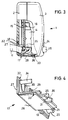
- a plug 14 connected to a line bundle 11 required for the operation of the device is coupled to a plug socket 16 (FIG. 3) contacted on a printed circuit board 15 and subsequently one in which Housing 1 designed and provided for the plug insertion opening 18 covered with a wall component 17 to be described in the following as an angle piece.
- the joint between the wall component 17 and the unspecified walls of the housing 1, on which the opening 18 is formed, is designed to be self-locking, at least insofar as the wall component 17 is concerned, that the device can also be attached to the housing 1 without the wall component 17, can be attached to the holder 5.
- the bushing 20 formed on an arm 19 of the wall component 17 has a through hole 21 for the passage of the screw 4.
- the wall component 17 is indirectly attached due to a flush construction between the holder 5 and the housing 1.
- the wall component 17 with the Screwed housing 1. Accordingly, a thread corresponding to the screw 4 is formed in the bushing 20.
- the device shown on the front has a display 25 covered by a lens 24 and is designated by 26 one of several keys by means of which the functions of the device can be controlled.
- the wall component 17, as a cover for the opening 18 with a wall element 27, forms part of the rear wall of the housing 1 and, with the other wall element 28, forms part of a side wall formed jointly by the two housing shells 2 and 3 selected embodiment, an opening 29 is provided in the wall element 27 for the passage of the cable formed by the shrink tube 11.
- the side view Fig. 3 shows the function of the housing component 17 as an elbow in that the opening 18 formed on two intersecting walls of the housing 1, the insertion of the plug 14 and optional routing of the cable bundle 11 only by plugging the housing component 17 flush with the Housing walls in which the opening 18 is recessed is closed.
- folds 32 and 33 are formed on the wall elements 27, 28 of the housing component 17 such that they are effective in opposite directions. That is, the fold 32 of the one wall element 27 points, with respect to the housing 1 inwards, the fold 33 of the other wall element 28 outwards.
Landscapes
- Engineering & Computer Science (AREA)
- Microelectronics & Electronic Packaging (AREA)
- Physics & Mathematics (AREA)
- General Physics & Mathematics (AREA)
- Architecture (AREA)
- Civil Engineering (AREA)
- Structural Engineering (AREA)
- Closures For Containers (AREA)
- Connector Housings Or Holding Contact Members (AREA)
Applications Claiming Priority (2)
| Application Number | Priority Date | Filing Date | Title |
|---|---|---|---|
| DE9315970U | 1993-10-20 | ||
| DE9315970U DE9315970U1 (de) | 1993-10-20 | 1993-10-20 | Anordnung zum Verschließen einer Öffnung in einem Gehäuse |
Publications (2)
| Publication Number | Publication Date |
|---|---|
| EP0650228A2 true EP0650228A2 (fr) | 1995-04-26 |
| EP0650228A3 EP0650228A3 (fr) | 1996-10-30 |
Family
ID=6899632
Family Applications (1)
| Application Number | Title | Priority Date | Filing Date |
|---|---|---|---|
| EP94115814A Withdrawn EP0650228A3 (fr) | 1993-10-20 | 1994-10-07 | Dispositif de fermeture d'une ouverture dans un boîte. |
Country Status (2)
| Country | Link |
|---|---|
| EP (1) | EP0650228A3 (fr) |
| DE (1) | DE9315970U1 (fr) |
Cited By (5)
| Publication number | Priority date | Publication date | Assignee | Title |
|---|---|---|---|---|
| EP1372365A1 (fr) * | 2002-06-14 | 2003-12-17 | WIELAND ELECTRIC GmbH | Borne à connexion |
| EP1380240A1 (fr) | 2002-07-11 | 2004-01-14 | Industrie Scaffalature Arredamenti- ISA SpA | Panneau pour le cablage de cables et de fils |
| EP1167902A3 (fr) * | 2000-06-20 | 2004-05-26 | Whirlpool Corporation | Unité centrale groupant les composants électroniques d'un réfrigérateur, d'un congélateur ou d'un autre appareil similaire |
| EP1172769A3 (fr) * | 2000-07-14 | 2005-01-19 | Siemens Aktiengesellschaft | Tachygraphe avec un boítier parallèlépipédique plat |
| WO2010000524A1 (fr) * | 2008-07-03 | 2010-01-07 | Robert Bosch Gmbh | Appareil de commande pour des moyens de protection des occupants d'un véhicule à moteur et procédé d'assemblage d'un tel appareil de commande |
Families Citing this family (8)
| Publication number | Priority date | Publication date | Assignee | Title |
|---|---|---|---|---|
| DE9413475U1 (de) * | 1994-08-20 | 1994-10-13 | Mannesmann Kienzle Gmbh, 78052 Villingen-Schwenningen | Fahrtschreiber mit Mitteln zur geräteseitigen Befestigung eines den Geberleitungen zugeordneten Schutzrohres |
| DE19520010C1 (de) * | 1995-05-27 | 1996-09-19 | Krone Ag | Sicherheitseinrichtung für ein Kunststoffgehäuse |
| DE19601518B4 (de) * | 1996-01-17 | 2016-05-12 | Wabco Gmbh | Gehäuse für eine elektrische Baugruppe |
| FR2745652B1 (fr) * | 1996-03-01 | 1998-06-05 | Ricard Claude | Boitier de taximetre perfectionne |
| DE10104213B4 (de) * | 2001-01-31 | 2006-01-26 | Haendler Gmbh & Co. Kg Elektro-Installationssysteme | Plombiereinrichtung |
| DE102010001411B4 (de) * | 2010-02-01 | 2017-12-28 | Te Connectivity Germany Gmbh | Gehäuse für eine elektrische Schaltung |
| DE102013010364B3 (de) * | 2013-06-21 | 2014-11-27 | Wieland Electric Gmbh | Leitungsanschluss |
| CN105977721B (zh) * | 2016-06-23 | 2018-09-25 | 常州格力博有限公司 | 工作器具外部电源线固定装置 |
Family Cites Families (5)
| Publication number | Priority date | Publication date | Assignee | Title |
|---|---|---|---|---|
| DE8510161U1 (de) * | 1985-04-04 | 1985-06-05 | Siemens AG, 1000 Berlin und 8000 München | Kabelführung in das Gehäuse eines Gerätes |
| JPH01502154A (ja) * | 1986-11-28 | 1989-07-27 | ウェストブルック,ロバート ローランド | データ通信コネクタの為の壁取付けシステム |
| JP2572255B2 (ja) * | 1988-03-25 | 1997-01-16 | チノン株式会社 | 電気機器の筐体 |
| US5006960A (en) * | 1990-01-11 | 1991-04-09 | Ncr Corporation | Means for routing connection cables out of a table top terminal |
| US5221813A (en) * | 1991-12-12 | 1993-06-22 | Ncr Corporation | Cable block for controlling cable routing in a terminal |
-
1993
- 1993-10-20 DE DE9315970U patent/DE9315970U1/de not_active Expired - Lifetime
-
1994
- 1994-10-07 EP EP94115814A patent/EP0650228A3/fr not_active Withdrawn
Cited By (6)
| Publication number | Priority date | Publication date | Assignee | Title |
|---|---|---|---|---|
| EP1167902A3 (fr) * | 2000-06-20 | 2004-05-26 | Whirlpool Corporation | Unité centrale groupant les composants électroniques d'un réfrigérateur, d'un congélateur ou d'un autre appareil similaire |
| EP1172769A3 (fr) * | 2000-07-14 | 2005-01-19 | Siemens Aktiengesellschaft | Tachygraphe avec un boítier parallèlépipédique plat |
| EP1372365A1 (fr) * | 2002-06-14 | 2003-12-17 | WIELAND ELECTRIC GmbH | Borne à connexion |
| EP1380240A1 (fr) | 2002-07-11 | 2004-01-14 | Industrie Scaffalature Arredamenti- ISA SpA | Panneau pour le cablage de cables et de fils |
| WO2010000524A1 (fr) * | 2008-07-03 | 2010-01-07 | Robert Bosch Gmbh | Appareil de commande pour des moyens de protection des occupants d'un véhicule à moteur et procédé d'assemblage d'un tel appareil de commande |
| US8693205B2 (en) | 2008-07-03 | 2014-04-08 | Robert Bosch Gmbh | Control unit for personal protection device for a vehicle and method for assembling such a control unit |
Also Published As
| Publication number | Publication date |
|---|---|
| EP0650228A3 (fr) | 1996-10-30 |
| DE9315970U1 (de) | 1993-12-02 |
Similar Documents
| Publication | Publication Date | Title |
|---|---|---|
| DE10233127C1 (de) | Vorrichtung zur Wanddurchführung von Rohrleitungen, Schläuchen oder elektrischen Kabeln für Kraftfahrzeuge | |
| DE60300484T2 (de) | Steckverbinderanordnung für ein standardisiertes elektrisches oder optisches Kabel | |
| EP0650228A2 (fr) | Dispositif de fermeture d'une ouverture dans un boîte | |
| EP2824784B1 (fr) | Boîtier d'installation | |
| DE102012107516B4 (de) | Befestigungsvorrichtung zur Befestigung eines elektronischen Geräts in einem Fahrzeug | |
| DE102017108320B4 (de) | Flachteilhalter für die Befestigung eines Flachteils an einem Rahmengestell eines Schaltschranks und ein entsprechender Schaltschrank | |
| DE10355350B4 (de) | Elektromodul | |
| DE60122099T2 (de) | Steck-Verbindungseinrichtung für Zusatzkomponente | |
| DE102012102842B4 (de) | Befestigung und Abdichtung von Steckanschlussmodulen in einer Gehäusewand | |
| DE102012007163B4 (de) | Elektromechanische Steckverbindungseinrichtung und damit ausgestattete elektrische Vorrichtung | |
| DE102015006440A1 (de) | Integrale Erdungsdurchführung | |
| DE19601518B4 (de) | Gehäuse für eine elektrische Baugruppe | |
| EP0697681B1 (fr) | Tachygraphe avec moyens de fixation à l'appareil d'un tube de protection associé aux lignes des capteurs | |
| DE9305756U1 (de) | Kombinierte Lade- und Fluidsteckvorrichtung | |
| DE102005056214B3 (de) | Vorrichtung zum Führen von Kabeln oder Leitungen | |
| DE202018002454U1 (de) | USB-Erweiterungsschnittstelle, USB-Schnittstellenanordnung und Steuerschrank für Elektrogeräte | |
| DE102007045280B3 (de) | Adapter für elektrische Baugruppe | |
| DE4420983A1 (de) | Gehäuse für elektronische Steckbaugruppen | |
| DE102005000074A1 (de) | Aufnahmegehäuse für ein Handwerkzeuggerät | |
| EP0838982B1 (fr) | Capot couvrant le connecteur d'un appareil électronique | |
| DE9204623U1 (de) | Gehäuse für eine elektrische oder elektronische Vorrichtung, insbesondere für eine Lichtschranke o.dgl. | |
| DE102006036097B3 (de) | Steckverbinder, Anordnung mit Steckverbinder und Verfahren zur Montage | |
| AT517608A4 (de) | Elektronikeinheit für ein Durchflussmessgerät | |
| DE102004006319B4 (de) | Gassack-Einheit | |
| DE10226489B4 (de) | Anschlussverbinder |
Legal Events
| Date | Code | Title | Description |
|---|---|---|---|
| PUAI | Public reference made under article 153(3) epc to a published international application that has entered the european phase |
Free format text: ORIGINAL CODE: 0009012 |
|
| AK | Designated contracting states |
Kind code of ref document: A2 Designated state(s): AT CH DE FR GB LI |
|
| PUAL | Search report despatched |
Free format text: ORIGINAL CODE: 0009013 |
|
| AK | Designated contracting states |
Kind code of ref document: A3 Designated state(s): AT CH DE FR GB LI |
|
| RAP1 | Party data changed (applicant data changed or rights of an application transferred) |
Owner name: VDO ADOLF SCHINDLING AG |
|
| STAA | Information on the status of an ep patent application or granted ep patent |
Free format text: STATUS: THE APPLICATION IS DEEMED TO BE WITHDRAWN |
|
| 18D | Application deemed to be withdrawn |
Effective date: 19970501 |