EP0650269A2 - Kommunikationsprotokoll für eine Anordnung von Kommunikationssatelliten mit hoher Datenrate - Google Patents
Kommunikationsprotokoll für eine Anordnung von Kommunikationssatelliten mit hoher Datenrate Download PDFInfo
- Publication number
- EP0650269A2 EP0650269A2 EP94307754A EP94307754A EP0650269A2 EP 0650269 A2 EP0650269 A2 EP 0650269A2 EP 94307754 A EP94307754 A EP 94307754A EP 94307754 A EP94307754 A EP 94307754A EP 0650269 A2 EP0650269 A2 EP 0650269A2
- Authority
- EP
- European Patent Office
- Prior art keywords
- control center
- network control
- sending
- source
- signal
- Prior art date
- Legal status (The legal status is an assumption and is not a legal conclusion. Google has not performed a legal analysis and makes no representation as to the accuracy of the status listed.)
- Granted
Links
Images



Classifications
-
- H—ELECTRICITY
- H04—ELECTRIC COMMUNICATION TECHNIQUE
- H04B—TRANSMISSION
- H04B7/00—Radio transmission systems, i.e. using radiation field
- H04B7/14—Relay systems
- H04B7/15—Active relay systems
- H04B7/185—Space-based or airborne stations; Stations for satellite systems
- H04B7/18523—Satellite systems for providing broadcast service to terrestrial stations, i.e. broadcast satellite service
Definitions
- the present invention relates generally to satellite communication systems, and more particularly, to a communication protocol for use with a high data rate satellite communication system that provides data, voice and video communication between individuals.
- Satellite-based systems have been employed for many years to distribute voice, data and video signals for global broadcasting of news and sporting events, for example.
- direct broadcast television systems are available that provide for broadcasting of television signals from up to 100 stations using a single satellite. Individuals install an antenna and a satellite receiver that receives the broadcasts directly by way of the satellite and display them on a television monitor.
- a video telephone system that employs a small (3-4 inch) television monitor in combination with a conventional telephone.
- the video telephone system typically uses fiber optic links to provide a sufficient bandwidth to carry the video along with the voice signals.
- this type of system does not have enough bandwidth to provide for full motion video.
- VSAT very small aperture terminal
- the satellite acts as a bit pipe, providing a network link between two terrestrial nodes, and is a two-hopped system with a hub in the middle to route calls, or packets.
- This high data rate satellite communication system comprises a plurality of very small user terminals (VSAT's) that are linked by and that communicate with each other by way of a satellite relay system.
- VSAT's very small user terminals
- a network control center provides control signals that control the satellite relay system and coordinate linking of terminals to each other.
- the system employs frequency division multiplexing on uplinks from the terminals and the network control center to the satellite relay system.
- the system employs time division multiplexing on downlinks from the satellite relay system to the terminals and the network control center.
- other uplink and downlink multiplexing schemes may also be used.
- the satellite does not act like a link in the network.
- Interactive services such as personal videoconferencing, and the like, will not tolerate a two-hop delay.
- the satellite acts as a node.
- This new system must also accommodate a larger number of users, and larger number of potential users for packet switched or circuit switched data, but none-the-less must provide connection-oriented communications, although some connectionless communication may also be provided for.
- resources are assigned to various communication source and destination terminals on a temporary call-by-call basis.
- the satellite in this new system is no longer just a bit-pipe-in-the-sky.
- the additional problem of allocating satellite resources such as assigning uplink and downlink physical channels to source and destination user terminals must be solved.
- This problem is new to multibeam satellite communication architectures using digital traffic, on-board demodulation, routing and remodulation, with or without the use of FDM uplinks and TDM downlinks.
- a communication protocol for use with a high data rate satellite communication system that provides for the communication of data, voice and video between individuals.
- These protocols build on existing standardized protocols, namely, ISDN.
- a communication protocol for use with a high data rate satellite communication system that employs frequency reuse and on-board demodulation and routing or switching and a network control center for call setup, monitoring and teardown.
- the present invention is a communication protocol for use with a high data rate satellite communication system.
- the satellite communication system comprises a plurality of very small user terminals that are linked by and that communicate with each other by way of a satellite relay system. Communication is achieved from terminal to terminal in a single hop.
- a network control center provides control signals that control the satellite relay system and coordinate linking of terminals to each other.
- the system employs frequency division multiplexing on uplinks from the terminals and the network control center to the satellite relay system.
- the system employs time division multiplexing on down-links from the satellite relay system to the terminals and the network control center, although other multiplexing schemes may be used on the uplink and downlink.
- Each user terminal comprises a transceiver for modulating and demodulating input and output data, and an antenna for transmitting and receiving encoded data to and from the satellite relay system. Additionally, a user terminal that is configured for receiving and transmitting video contains a data compression circuit for compressing input data and decompressing output data.
- the satellite relay system is comprised of a satellite, a wide area antenna, a plurality of satellite receive antennas, a plurality of satellite transmit antennas, and a signal processor.
- the wide area antenna is provided for communicating control signals between the user terminals and the network control center.
- the plurality of satellite receive antennas operate in a first frequency band and produce a first plurality of beams that cover a predefined service area.
- the plurality of satellite receive antennas are adapted to receive time division multiplexed data from a source user terminal on a first beam.
- the plurality of satellite transmit antennas operate in a second frequency band and produce a second plurality of beams that cover the service area.
- the plurality of satellite transmit antennas are adapted to transmit the time division multiplexed data to a destination user terminal on a second beam.
- the second beam may be geographically colocated with the first beam, depending upon the respective locations of the source and destination user terminals.
- the signal processor is adapted to demodulate frequency division multiplexed data received on the first beam from the source user terminal. It then routes the demodulated data so that it can be transmitted on the second beam to the destination user terminal. The signal processor then remodulates the demodulated data to provide encoded data comprising time division multiplexed data Finally the signal processor transmits the time division multiplexed data on the second beam to the destination user terminal. It is to be understood that other multiplexing schemes may be used.
- the present invention is a communication protocol or method that is as follows. Operational source and user terminals continually monitor downlink frequencies to determine which beam they are in. Each terminal scans through each of the four down-link frequencies at each of two polarizations and collects bit error measurements on known bits on the downlink data stream. Each terminal selects the strongest frequency determined by the fewest measured bit errors. Beam identification is embedded in framing information and this information is used by each terminal to identify which beam it is in.
- a source terminal requests a physical channel to transmit on. This is known as call setup.
- Call setup is achieved by generating source and destination IDs and identifying which beam the source user terminal is in.
- the source user terminal then sends the above information to the network control center by randomly choosing among allowable frequencies within the wide area coverage beam, and organizing the data that is to be transmitted into a packet.
- This packet has a standardized format, called high-level data link control (HDLC), which is similar to the format used on the D channel in the ISDN.
- HDLC high-level data link control
- the source user terminal bursts the packet to the satellite relay system where it is translated in frequency and amplified and sent to the network control center without using on-board demodulation or remodulation. This is known as a bent-pipe architecture.
- the network control center then accesses these packets as they are burst to it.
- an acknowledgement signal is sent to the source user terminal by the network control center by way of an "orderwire" channel.
- the network control center determines whether contention has occurred by computing a cyclic redundancy check (CRC) code for the packet and comparing this against the transmitted CRC.
- CRC cyclic redundancy check
- the source user terminal does not receive an acknowledgement signal after a sufficient time delay (for example, twice the geosynchronous altitude delay or about 0.25 seconds) then it waits another period of time, the length of which is chosen randomly to avoid contention occurring again and again, and retransmits the data packet.
- a sufficient time delay for example, twice the geosynchronous altitude delay or about 0.25 seconds
- the network control center assigns the source user terminal to a particular uplink channel and a downlink channel.
- the use of the present Aloha channel and technique permits the system to cleanly and simply establish its data links.
- the orderwire uplink channel is the uplink channel of the network control center.
- a second uplink channel may be used to communicate with or to configure the router in the satellite relay system.
- the orderwire uplink processes information that is transmitted to the source and destination user terminals. This information is broadcast, or more precisely multicast on preassigned agreed upon channels of every downlink beam. Thereafter, the uplinked data is demodulated, routed to every downlink beam where it is multiplexed with other data channels, then remodulated and downlinked to every user terminal.
- the orderwire uplink is only from the network control center to the satellite relay system, and uses the channel without demodulation and remodulation.
- the orderwire downlink is only from the satellite relay system to the user terminals, and uses the channels with demodulation and remodulation. Each user terminal monitors its orderwire downlink channel to recognize and extract messages addressed to it.
- the network control center calls the destination user terminal. Again, this takes place by way of the orderwire channel.
- the destination user terminal accesses data addressed to it off the orderwire channel, and if it is not busy, it sends an OFFHOOK message to the network control center using the Aloha channel along with data indicative of which beam it is in.
- Acknowledgement from the network control center is performed by way of the orderwire channel, and the destination user terminal is assigned its uplink channel and downlink channel (frequency for FDM, and time slot for TDM). Other multiplexing schemes may also be readily employed.
- Data flow, call monitoring and terminal polling is as follows. Once the source and destination user terminals have been assigned their beams and frequency and time slots, the network control center reconfigures the routes to setup the end-to-end data link. Thereafter, data transfer between terminals is generally independent of the network control center. Once the communication link between the user terminals is established, input data generated at a source user terminal is multiplexed and transmitted to the satellite relay system. The satellite relay system demodulates the data, routes it so that it is retransmitted on a beam that communicates with the destination user terminal, remultiplexes and remodulates the data, and then transmits the multiplexed data to the destination user terminal.
- the network control center it is necessary for the network control center to monitor the calls so that system resources are not unnecessarily tied up if a connection is lost. This is achieved by causing both terminals to send periodic messages to the network control center indicating that they are active on the network, or the network control center may periodically poll each terminal and terminate a call if either terminal is unresponsive or provides a signal indicating that it is ONHOOK (has hung up).
- Call termination is as follows. If a call is terminated, in that the network control center received a HANGUP signal from one terminal or either terminal is unresponsive to polling, or either terminal fails to send a monitoring message to the network control center within a required time period, a number of system resources are released. These resources include the uplink channels for both terminals including the satellite demodulators, the downlink channels for both terminals and the path through the router 80 that was reserved for the terminals. Signals are sent to both terminals by way of the orderwire channel to cease transmitting. Each terminal may then send an acknowledgement signal by way of the Aloha channel (wide area coverage beam) to the network control center to reduce interference with other terminals.
- Aloha channel wide area coverage beam
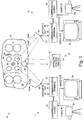
- Fig. 1 illustrates a high data rate satellite communication system 10 in which the present invention may be employed.
- the system 10 comprises a plurality of very small user terminals 11, 12 (corresponding to first and second user terminals 11, 12) that are linked by and that communicate with each other by way of a satellite relay system 13.
- a network control center 14 provides control signals that control the satellite relay system 13 and coordinate linking of terminals 11, 12 to each other.
- the system 10 employs frequency division multiplexing on uplinks from the terminals 11, 12 and the network control center 14 to the satellite relay system 13.
- the system 10 employs time division multiplexing on downlinks from the satellite relay system 10 to the terminals 11, 12 and the network control center 14.
- Each user terminal 11, 12 comprises a data compression coder/decoder (CODEC) circuit 22 for compressing input data and decompressing output data, a transceiver 23 for modulating and demodulating input and output data, and an antenna 25 for transmitting and receiving encoded data to and from the satellite relay system 13.
- CDEC data compression coder/decoder
- the compression circuit 22 is replaced by interface circuitry that is adapted to interface to a data source, such as a local area network, a terminal or computer, or a data communication line, or the like.
- the satellite relay system 13 is comprised of a satellite 30, a plurality of receive antennas 32, a plurality of transmit antennas 31, a wide area antenna 35, and a signal processor 36.
- Respective pluralities of feed horns 33, 34 are provided to feed data to and from the respective transmit and receive antennas 31, 32.
- the wide area antenna is provided for communicating control signals between the user terminals 11, 12 and the network control center 14.
- the network control center 14 comprises a control processor 15 for generating configuration and control signals that link the user terminals 11, 12 by way of the satellite relay system 13, and an antenna 16 coupled to the control processor 15 for transmitting and receiving the control signals.
- the plurality of receive antennas 32 operate in a first frequency band and produce a first plurality of beams (shown in Fig. 5) that cover a predefined area.
- the plurality of receive antennas 32 are adapted to receive frequency division multiplexed data from the first user terminal 11 on a first beam.
- the plurality of transmit antennas 31 operate in a second frequency band and produce a second plurality of beams that cover the predefined area.
- the plurality of transmit antennas 31 are adapted to transmit the time division multiplexed data to the second user terminal 12 on a second beam. It is to be understood that the second beam may be geographically colocated with the first beam, depending upon the respective locations of the source and destination user terminals 11, 12.
- the signal processor 36 is adapted to demodulate frequency division multiplexed data received on the first beam from the first user terminal 11, route the demodulated data so that it is transmitted on the second beam to the second user terminal 12, remodulate the demodulated data to provide encoded data comprising time division multiplexed data, and transmit the frequency division multiplexed data on the second beam to the second user terminal 12. It is to be understood that other multiplexing schemes may be readily employed, and that the present invention is not limited to the herein-described multiplexing schemes.
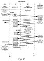
- FIG. 2 illustrates the signal flow of a call setup portion 41 of the communication method 40.
- a call setup sequence is implemented between a source user terminal 11, the network control center 14, and a destination user terminal 12.
- Operational source and user terminals 11, 12 continually monitor downlink frequencies to determine which beam they are in. Each terminal scans through each of the downlink frequencies at each polarization and collects bit error measurements on known bits on the downlink data stream. Each terminal selects the strongest frequency determined by the fewest measured bit errors. Beam identification is embedded in framing information and this information is used by each terminal to identify which beam it is in.
- a source user terminal 11 must request a physical channel to transmit on. This is done by generating source and destination IDs and identifying which beam the terminals are in. The source user terminal 11 then sends the above information to the network control center 14 by randomly choosing among allowable frequencies within the wide area coverage beam, and organizing the data that is to be transmitted into a packet.
- This packet has a standardized format called high-level data link control (HDLC), which is similar to the format used on the D channel in the ISDN.
- HDLC high-level data link control
- the source user terminal 11 bursts the packet to the satellite relay system 13 where it is translated in frequency and amplified and sent to the network control center 14 without using on-board demodulation and remodulation. This is known as a bent-pipe architecture.
- the network control center 14 then uses its demodulators to access these packets as they are burst to it.
- the source user terminal 11 requests a physical channel to transmit on. This is referred to as call setup.
- Call setup is achieved by generating source and destination IDs and identifying which beam the source user terminal 11 is in.
- the source user terminal 11 then sends the above information to the network control center 14 by randomly choosing among allowable frequencies within the wide area coverage beam, and organizing the data that is to be transmitted into a packet.
- This packet has a standardized format, similar to the format used on the D channel in the ISDN.
- a high-level data link control (HDLC) protocol is used.
- the source user terminal 11 sends the information to the network control center 14 by randomly choosing among allowable frequencies within the wide area coverage beam, and organizing the data into the data packet.
- This data packet has a standardized format, known as a high-level data link control (HDLC) packet.
- the source user terminal 11 then bursts the data packet to the satellite relay system 13 where it is translated in frequency, amplified, and retransmitted to the network control center 14 without using the demodulation and remodulation processes. This is known as a bent-pipe architecture.
- the network control center 14 employs demodulators that access the data packets as they are burst to it.
- an acknowledgement signal is sent to the source user terminal 11 by the network control center 14 by way of an "orderwire" channel.
- the network control center 14 determines whether contention has occurred by computing a cyclic redundancy check (CRC) code for the packet and comparing this against the transmitted CRC.
- CRC cyclic redundancy check
- an acknowledgement signal is sent to the source user terminal 11 by the network control center 13 by way of the "orderwire" channel.
- the source user terminal does not receive an acknowledgement signal after a sufficient time delay (for example, twice the geosynchronous altitude delay or about 0.25 seconds) then it waits another period of time, the length of which is chosen randomly to avoid contention occurring again and again, and retransmits the data packet. This is referred to herein as an "Aloha" random access technique.
- the network control center 14 assigns the source user terminal 11 to a particular uplink channel and a downlink channel.
- This request cycle using the Aloha channel and channel assignment using the orderwire channel may take several iterations if uplink interference is a problem for some TDM channels.
- the orderwire uplink channel is the uplink channel of the network control center 14.
- a second uplink frequency may be used to communicate with or to configure the router 80 in the satellite relay system 13.
- the orderwire uplink processes information that is transmitted to the source and destination user terminals 11, 12. This information is broadcast, or more precisely multicast on preassigned agreed upon channels of every downlink beam.
- the uplinked data is demodulated, routed to every downlink beam where it is multiplexed with other data channels, then remodulated and downlinked to every user terminal.
- Each user terminal continually monitors this downlink channel and can recognize and extract messages addressed to it.
- the orderwire uplink channel (or channels) is the channel of the network control center 14.
- a second uplink channel may be used to communicate with or to configure the router in the satellite relay system 13.
- the orderwire uplink channel processes information that is transmitted to the source and destination user terminals 11, 12. This information is broadcast, or more precisely multicast on, say, every channel 1, for example, of every downlink beam. Thereafter, the uplinked data is demodulated, routed to every downlink beam where it is time division multiplexed with other data channels, then remodulated and downlinked to every user terminal 11, 12. Each user terminal 11, 12 continually monitors this downlink channel and can recognize and extract messages addressed to it.
- the orderwire uplink is only from the network control center 14 to the satellite relay system 13, and uses the demodulation and remodulation.
- the orderwire down-link is only from the satellite relay system 13 to the user terminals 11, 12, and uses the demodulation and remodulation.
- Each user terminal 11, 12 monitors its orderwire downlink channel to recognize and extract messages addressed to it.
- the network control center 14 calls the destination user terminal 12. Again, this takes place by way of the orderwire channel.
- the destination user terminal 12 accesses data addressed to it off the orderwire channel, and if it is not busy, it sends an OFFHOOK message to the network control center 14 using the Aloha channel along with data indicative of which beam it is in and best uplink frequency.
- Acknowledgement from the network control center 14 is performed by way of the orderwire channel, and the destination user terminal 12 is assigned its uplink and downlink channels (frequency for FDM, and time slot for TDM).
- FIG. 3a illustrates the signal flow of a data flow and call monitoring portion of the communication method 40 using terminal packets.
- Fig. 3b illustrates the signal flow of a data flow and call monitoring portion of the communication method 40 using terminal polling.
- the network control center 14 reconfigures the routes to set-up the end-to-end data link. Thereafter, data transfer between terminals 11, 12 is generally independent of the network control center 14.
- input data generated at a source user terminal 11 is frequency division multiplexed and transmitted to the satellite relay system 13.
- the satellite relay system 13 demodulates the data, routes it so that it is retransmitted on a beam that communicates with the destination user terminal 12, remodulates the data, and then transmits the time division multiplexed data to the destination user terminal 12.
- the network control center 14 it is necessary for the network control center 14 to monitor the calls so that system resources are not unnecessarily tied up if a connection is lost. This is achieved by causing both terminals 11, 12 to send periodic messages (HDLC packets) embedded in the data stream to the network control center 14 (Fig. 3a) indicating that they are active on the network. Alternatively, the network control center 14 may periodically poll each terminal 11, 12 (Fig. 3b) and terminate a call if either terminal 11, 12 is unresponsive or provides a signal indicating that it is ONHOOK (has hung up).
- HDLC packets periodic messages embedded in the data stream
- the network control center 14 may periodically poll each terminal 11, 12 (Fig. 3b) and terminate a call if either terminal 11, 12 is unresponsive or provides a signal indicating that it is ONHOOK (has hung up).
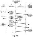
- Fig. 4a illustrates the signal flow of a call teardown portion of the communication method 40 when a terminal hangs up.
- Fig. 4b illustrates the signal flow of a call teardown portion of the communication method 40 when there is a timeout.
- a call is terminated, in that the network control center 14 receives a HANGUP signal from a terminal 11, 12, or either terminal 11, 12 is unresponsive to polling, or either terminal 11, 12 fails to send a monitoring message to the network control center 14 within a required time period, a number of system resources are released. These resources include the uplink channels for both terminals 11, 12, including the satellite demodulators, the downlink channels for both terminals 11, 12, and the path through the router 80 that was reserved for the terminals 11, 12. Signals are sent to both terminals 11, 12 by way of the orderwire channel to cease transmitting. Each terminal 11, 12 may then send an acknowledgement signal by way of the Aloha channel (wide area coverage beam) to the network control center 14 to reduce interference with other terminals.
- Aloha channel wide area coverage beam
- a timeout occurs, in that data flow monitoring has timed-out if no active line packet is received within a predetermined time period, or if no response is received to a polling request, the system resources are released.
- the signals transferred between the network control center 14, the satellite relay system 13 and the user terminals 11, 12 are substantially the same as for the call termination procedure described with reference to Fig. 4a.
- Fig. 5 illustrates a typical beam pattern employed by the system 10 of Fig. 1.
- Fig. 5 shows the use of 24 beams that completely cover a desired operating area; in this case the continental United States, Alaska (AK) and Hawaii (HI).
- the respective beams are number with an identifying number (1, 2, 3, 4) that indicates which respective subband is assigned to each beam.
- the subbands are illustrated in Figs. 6a and 6b. More particularly, Figs. 6a and 6b show the characteristics of uplink and downlink beams of the beam pattern shown in Fig. 5. As can be seen from Fig.
- Fig. 5 shows the transmit bands that comprise four 120 MHz subbands and a 10 MHz wide area coverage (CONUS) subband that extends from 29.5 GHz to 30.0 GHz.
- Fig. 6b shows the receive bands that comprise four 120 MHz subbands and a 10 MHz wide area coverage (CONUS) subband that extends from 19.7 GHz to 20.2 GHz. These frequencies are in the Ka band.
Landscapes
- Engineering & Computer Science (AREA)
- Physics & Mathematics (AREA)
- Astronomy & Astrophysics (AREA)
- Aviation & Aerospace Engineering (AREA)
- General Physics & Mathematics (AREA)
- Computer Networks & Wireless Communication (AREA)
- Signal Processing (AREA)
- Radio Relay Systems (AREA)
- Two-Way Televisions, Distribution Of Moving Picture Or The Like (AREA)
- Data Exchanges In Wide-Area Networks (AREA)
- Communication Control (AREA)
- Mobile Radio Communication Systems (AREA)
Applications Claiming Priority (2)
| Application Number | Priority Date | Filing Date | Title |
|---|---|---|---|
| US08/141,779 US5485464A (en) | 1993-10-21 | 1993-10-21 | Communication protocol for a high data rate satellite communication system |
| US141779 | 1993-10-21 |
Publications (3)
| Publication Number | Publication Date |
|---|---|
| EP0650269A2 true EP0650269A2 (de) | 1995-04-26 |
| EP0650269A3 EP0650269A3 (de) | 1997-12-03 |
| EP0650269B1 EP0650269B1 (de) | 2000-08-23 |
Family
ID=22497212
Family Applications (1)
| Application Number | Title | Priority Date | Filing Date |
|---|---|---|---|
| EP94307754A Expired - Lifetime EP0650269B1 (de) | 1993-10-21 | 1994-10-21 | Kommunikationsprotokoll für eine Anordnung von Kommunikationssatelliten mit hoher Datenrate |
Country Status (4)
| Country | Link |
|---|---|
| US (1) | US5485464A (de) |
| EP (1) | EP0650269B1 (de) |
| JP (1) | JP2968692B2 (de) |
| DE (1) | DE69425625T2 (de) |
Cited By (3)
| Publication number | Priority date | Publication date | Assignee | Title |
|---|---|---|---|---|
| WO1999045473A1 (en) * | 1998-03-02 | 1999-09-10 | Deutsche Thomson-Brandt Gmbh | Method and device for processing data packets which have been received or are to be transmitted on a data channel |
| EP0884860A3 (de) * | 1997-06-13 | 2002-09-11 | Nippon Telegraph And Telephone Corporation | Kanalzuteilungsverfahren für ein Satellitkommunikationssystem |
| CN116367122A (zh) * | 2023-02-20 | 2023-06-30 | 南京汇邦信息科技有限公司 | 一种基于终端直通通信的信道管理系统 |
Families Citing this family (47)
| Publication number | Priority date | Publication date | Assignee | Title |
|---|---|---|---|---|
| JPH086898A (ja) * | 1994-06-21 | 1996-01-12 | Fujitsu Ltd | ポーリング代行装置 |
| US5542115A (en) * | 1994-06-24 | 1996-07-30 | Pioneer Tech Development Limited | Paging method and apparatus |
| US5659615A (en) * | 1994-11-14 | 1997-08-19 | Hughes Electronics | Secure satellite receive-only local area network with address filter |
| GB2300540B (en) * | 1995-03-31 | 1999-10-20 | Int Mobile Satellite Org | Communication method and apparatus |
| US5586121A (en) * | 1995-04-21 | 1996-12-17 | Hybrid Networks, Inc. | Asymmetric hybrid access system and method |
| US5835487A (en) | 1995-12-08 | 1998-11-10 | Worldspace International Network, Inc. | Satellite direct radio broadcast system |
| US5796726A (en) * | 1996-04-08 | 1998-08-18 | Ericsson Inc. | Systems and methods for random access in time division multiple access satellite radiotelephone communications |
| US7266686B1 (en) | 1996-05-09 | 2007-09-04 | Two-Way Media Llc | Multicasting method and apparatus |
| US5864547A (en) * | 1996-08-21 | 1999-01-26 | Hughes Electronics Corporation | Method and system for controlling uplink power in a high data rate satellite communication system employing on-board demodulation and remodulation |
| US5978363A (en) * | 1996-10-18 | 1999-11-02 | Telogy Networks, Inc. | System and method for multi-dimensional resource scheduling |
| US6230193B1 (en) * | 1996-10-31 | 2001-05-08 | 3Com Corporation | Method and apparatus supporting network communications |
| US6101180A (en) | 1996-11-12 | 2000-08-08 | Starguide Digital Networks, Inc. | High bandwidth broadcast system having localized multicast access to broadcast content |
| US6215776B1 (en) | 1997-10-08 | 2001-04-10 | Lockheed Martin Missiles & Space Company | Satellite communication system |
| BR9814030A (pt) * | 1997-11-14 | 2001-11-27 | Worldspace Man Corp | Protocolo de sinalização para um sistema derádiodifusão direto de satélite |
| US6201798B1 (en) | 1997-11-14 | 2001-03-13 | Worldspace Management Corporation | Signaling protocol for satellite direct radio broadcast system |
| US6052812A (en) | 1998-01-07 | 2000-04-18 | Pocketscience, Inc. | Messaging communication protocol |
| US6023458A (en) * | 1998-01-26 | 2000-02-08 | Gte Laboratories Incorporated | Method and system for distributing subscriber services using wireless bidirectional broadband loops |
| US6185265B1 (en) | 1998-04-07 | 2001-02-06 | Worldspace Management Corp. | System for time division multiplexing broadcast channels with R-1/2 or R-3/4 convolutional coding for satellite transmission via on-board baseband processing payload or transparent payload |
| US6320850B1 (en) | 1998-04-24 | 2001-11-20 | Trw Inc. | Satellite communication adaptive control coding |
| CN1134937C (zh) | 1998-07-21 | 2004-01-14 | 塔奇昂公司 | 通信系统内用于多址接入的方法和装置 |
| US6674730B1 (en) | 1998-08-04 | 2004-01-06 | Tachyon, Inc. | Method of and apparatus for time synchronization in a communication system |
| US6256483B1 (en) * | 1998-10-28 | 2001-07-03 | Tachyon, Inc. | Method and apparatus for calibration of a wireless transmitter |
| US6275500B1 (en) * | 1999-08-09 | 2001-08-14 | Motorola, Inc. | Method and apparatus for dynamic control of talk groups in a wireless network |
| US6674731B1 (en) | 1999-08-27 | 2004-01-06 | Tachyon, Inc. | Transmission and reception of TCP/IP data over a wireless communication channel |
| US6463070B1 (en) | 1999-08-27 | 2002-10-08 | Tachyon, Inc. | System and method for clock correlated data flow in a multi-processor communication system |
| US6665292B1 (en) | 1999-08-27 | 2003-12-16 | Tachyon, Inc. | Transmission and reception of TCP/IP data over a wireless communication channel |
| US6982969B1 (en) | 1999-09-28 | 2006-01-03 | Tachyon, Inc. | Method and system for frequency spectrum resource allocation |
| US6735188B1 (en) | 1999-08-27 | 2004-05-11 | Tachyon, Inc. | Channel encoding and decoding method and apparatus |
| US6532220B1 (en) | 1999-08-27 | 2003-03-11 | Tachyon, Inc. | System and method for efficient channel assignment |
| US6218896B1 (en) | 1999-08-27 | 2001-04-17 | Tachyon, Inc. | Vectored demodulation and frequency estimation apparatus and method |
| US6650636B1 (en) | 1999-08-27 | 2003-11-18 | Tachyon, Inc. | Transmission and reception of TCP/IP data over a wireless communication channel |
| US20010025377A1 (en) * | 1999-12-30 | 2001-09-27 | Hinderks Larry W. | High bandwidth transmission system and method having local insertion, delay play and demand play |
| US6950422B2 (en) * | 2001-03-19 | 2005-09-27 | Motorola, Inc. | Interference reduction within a communication system |
| AU2003249603A1 (en) * | 2002-04-29 | 2003-11-11 | Etherware, Llc | System for providing broadband mobile access from geostationary satellites to platforms using small, low profile antennas |
| US7523183B2 (en) * | 2003-01-07 | 2009-04-21 | International Business Machines Corporation | Locator for computer equipment |
| FR2892253B1 (fr) * | 2005-10-14 | 2007-12-28 | Thales Sa | Procede de generation et de demultiplexage d'un signal de contribution optimise, et systeme de diffusion regionalisee de donnees. |
| WO2008060757A2 (en) * | 2006-10-03 | 2008-05-22 | Viasat, Inc. | Large packet concatenation in satellite communication system |
| EP2074712B1 (de) * | 2006-10-03 | 2012-04-11 | ViaSat, Inc. | Netz-/volumen-übertragungs-vorabzuweisung von upstream-ressourcen in einem satelliten-kommunikationssystem |
| CN101573890A (zh) * | 2006-10-03 | 2009-11-04 | 维尔塞特公司 | 卫星通信系统中数据包的map触发转储 |
| CN101573891A (zh) * | 2006-10-03 | 2009-11-04 | 维尔塞特公司 | 卫星通信系统中最前面延时的串接 |
| WO2008044902A1 (en) * | 2006-10-13 | 2008-04-17 | Electronics And Telecommunications Research Institute | Relaying method of relay station(rs) using a direct relaying zone in multi-hop relay system |
| US7869759B2 (en) * | 2006-12-14 | 2011-01-11 | Viasat, Inc. | Satellite communication system and method with asymmetric feeder and service frequency bands |
| US9654206B1 (en) * | 2013-04-04 | 2017-05-16 | Lockheed Martin Corporation | Hub enabled single hop transport forward access |
| US10447385B2 (en) | 2016-03-04 | 2019-10-15 | Hughes Network Systems, Llc | Approaches for achieving improved capacity plans for a satellite communications system via interleaved beams from multiple satellites |
| US10355775B2 (en) | 2016-12-31 | 2019-07-16 | Hughes Network Systems, Llc | Approaches for improved frequency reuse efficiency and interference avoidance for a multi-beam satellite communications network |
| CN112615662B (zh) * | 2020-12-03 | 2022-10-28 | 北京国电高科科技有限公司 | 一种低轨卫星的mac层的数据传输方法 |
| CN113452432B (zh) * | 2021-06-30 | 2023-03-21 | 西南电子技术研究所(中国电子科技集团公司第十研究所) | 多波束低轨卫星通信下行资源动态分配方法 |
Family Cites Families (7)
| Publication number | Priority date | Publication date | Assignee | Title |
|---|---|---|---|---|
| JPS61214826A (ja) * | 1985-03-20 | 1986-09-24 | Nec Corp | 衛星通信用メツセ−ジ再送制御方式 |
| JPS6424523A (en) * | 1987-07-20 | 1989-01-26 | Mitsubishi Electric Corp | Dama communication system |
| US5278891A (en) * | 1988-04-29 | 1994-01-11 | Mobile Telecommunication Technologies | Ground-to-air telephone calling system and related method |
| JPH0234050A (ja) * | 1988-07-25 | 1990-02-05 | Nippon Telegr & Teleph Corp <Ntt> | 無線回線制御方式 |
| JPH03136417A (ja) * | 1989-10-23 | 1991-06-11 | Toshiba Corp | 衛星通信用交換装置 |
| JPH0425228A (ja) * | 1990-05-18 | 1992-01-29 | Nec Corp | 衛星地上局監視方式 |
| US5239540A (en) * | 1990-11-27 | 1993-08-24 | Scientific-Atlanta, Inc. | Method and apparatus for transmitting, receiving and communicating digital data signals with corresponding program data signals which describe the digital data signals |
-
1993
- 1993-10-21 US US08/141,779 patent/US5485464A/en not_active Expired - Lifetime
-
1994
- 1994-10-21 DE DE69425625T patent/DE69425625T2/de not_active Expired - Lifetime
- 1994-10-21 JP JP25715094A patent/JP2968692B2/ja not_active Expired - Lifetime
- 1994-10-21 EP EP94307754A patent/EP0650269B1/de not_active Expired - Lifetime
Non-Patent Citations (6)
| Title |
|---|
| AMES ET AL.: "Advanced Communications Payload for Mobile Applications" PROCEEDINGS OF THE SECOND INTERNATIONAL MOBILE SATELLITE CONFERENCE IMSC'90, 17 - 20 June 1990, OTTAWA, CN, pages 403-409, XP002042853 * |
| B.GHAFFARI ET AL.: "Multi-Media Integration in Multiple-Access Satellite Networks" IEEE INTERNATIONAL SYMPOSIUM ON INFORMATION THEORY, 24 - 28 June 1991, BUDAPEST, HU, page 210 XP000365597 * |
| FROMM ET AL.: "Digital Satellite Communication with on Board Switching system design criteria and implementation aspects" THE 14TH INTERNATIONAL COMMUNICATION SATELLITE SYSTEMS CONFERENCE AND EXHIBIT, 22 - 24 March 1992, WASHINGTON, US, pages 1515-1521, XP002042852 * |
| L.BELLA ET AL.: "Role of ISDN Signaling for a Satellite System with On-Board Processing." IEEE JOURNAL ON SELECTED AREAS IN COMMUNICATIONS, vol. 10, no. 6, 10 August 1992, NEW-YORK,US, pages 1066-1080, XP000296622 * |
| LEE ET AL.: "An Analysis of Uplink Multiple Access Protocols in Meshed VSAT Satellite Networks" TWELFTH ANNUAL INTERNATIONAL PHOENIX CONFERENCE ON COMPUTERS AND COMMUNICATIONS, 23 - 26 March 1993, TEMPE,US, pages 394-400, XP000370507 * |
| PONTANO ET AL.: "ISDN over Satellite Networks" COMMUNICATIONS-FUSING COMMAND, CONTROL AND INTELLIGENCE, vol. 2, no. 22.3, 11 - 14 October 1992, SAN DIEGO, US, pages 560-564, XP000346654 * |
Cited By (4)
| Publication number | Priority date | Publication date | Assignee | Title |
|---|---|---|---|---|
| EP0884860A3 (de) * | 1997-06-13 | 2002-09-11 | Nippon Telegraph And Telephone Corporation | Kanalzuteilungsverfahren für ein Satellitkommunikationssystem |
| WO1999045473A1 (en) * | 1998-03-02 | 1999-09-10 | Deutsche Thomson-Brandt Gmbh | Method and device for processing data packets which have been received or are to be transmitted on a data channel |
| US6810045B1 (en) | 1998-03-02 | 2004-10-26 | Thomson Licensing S.A. | Method and device for processing data packets which have been received or are to be transmitted on a data channel |
| CN116367122A (zh) * | 2023-02-20 | 2023-06-30 | 南京汇邦信息科技有限公司 | 一种基于终端直通通信的信道管理系统 |
Also Published As
| Publication number | Publication date |
|---|---|
| EP0650269A3 (de) | 1997-12-03 |
| JPH07226705A (ja) | 1995-08-22 |
| DE69425625D1 (de) | 2000-09-28 |
| DE69425625T2 (de) | 2000-12-28 |
| US5485464A (en) | 1996-01-16 |
| JP2968692B2 (ja) | 1999-10-25 |
| EP0650269B1 (de) | 2000-08-23 |
Similar Documents
| Publication | Publication Date | Title |
|---|---|---|
| US5485464A (en) | Communication protocol for a high data rate satellite communication system | |
| US5625624A (en) | High data rate satellite communication system | |
| US6278861B1 (en) | Mobile earth terminal with roaming capability | |
| EP1067712B1 (de) | Kommunikationssystem mit Satelliten auf niedriger Bahn und verteilten Übergangstationen | |
| US8335515B2 (en) | Radio network assignment and access system | |
| EP0705503B1 (de) | Multiplexvermittlungsstruktur für ein protokoll für rahmenzwischenschaltung in einem gemaschten satellitennetz | |
| US5926745A (en) | Network operations center for mobile earth terminal satellite communications system | |
| US5884142A (en) | Low earth orbit distributed gateway communication system | |
| US5841765A (en) | Demand-based connection management integrated services access terminal (ISAT) for satellite communication system | |
| US6078577A (en) | System and method for packet data communication | |
| US5815809A (en) | Mobile earth terminal communication device providing voice, data, facsimile, and/or roaming communication features | |
| KR20000075846A (ko) | 데이터 링크 동기를 위한 시스템 및 방법 | |
| US6771617B1 (en) | Frame relay protocol-based multiplex switching scheme for satellite mesh network | |
| EP1429474A2 (de) | Verfahren und Einrichtung zur Satellitenkommunikation | |
| AU2004231937B2 (en) | Radio network assignment and access system | |
| Evans et al. | An on‐board processing satellite payload for european mobile communications | |
| Kwan et al. | Technology requirements for mesh VSAT applications | |
| Liebowitz | COTS implementation of satellite-based, full-mesh multimedia networks | |
| Yoon | Very small aperture terminal(VSAT) networks | |
| MXPA99008580A (en) | Satellite communications system having distributed user assignment and resource assignment with terrestrial gateways |
Legal Events
| Date | Code | Title | Description |
|---|---|---|---|
| PUAI | Public reference made under article 153(3) epc to a published international application that has entered the european phase |
Free format text: ORIGINAL CODE: 0009012 |
|
| AK | Designated contracting states |
Kind code of ref document: A2 Designated state(s): DE FR GB |
|
| PUAL | Search report despatched |
Free format text: ORIGINAL CODE: 0009013 |
|
| AK | Designated contracting states |
Kind code of ref document: A3 Designated state(s): DE FR GB |
|
| 17P | Request for examination filed |
Effective date: 19980508 |
|
| RAP1 | Party data changed (applicant data changed or rights of an application transferred) |
Owner name: HE HOLDINGS, INC. |
|
| RAP1 | Party data changed (applicant data changed or rights of an application transferred) |
Owner name: HUGHES ELECTRONICS CORPORATION |
|
| 17Q | First examination report despatched |
Effective date: 19990215 |
|
| GRAG | Despatch of communication of intention to grant |
Free format text: ORIGINAL CODE: EPIDOS AGRA |
|
| GRAG | Despatch of communication of intention to grant |
Free format text: ORIGINAL CODE: EPIDOS AGRA |
|
| GRAH | Despatch of communication of intention to grant a patent |
Free format text: ORIGINAL CODE: EPIDOS IGRA |
|
| GRAH | Despatch of communication of intention to grant a patent |
Free format text: ORIGINAL CODE: EPIDOS IGRA |
|
| GRAA | (expected) grant |
Free format text: ORIGINAL CODE: 0009210 |
|
| AK | Designated contracting states |
Kind code of ref document: B1 Designated state(s): DE FR GB |
|
| REF | Corresponds to: |
Ref document number: 69425625 Country of ref document: DE Date of ref document: 20000928 |
|
| ET | Fr: translation filed | ||
| PLBE | No opposition filed within time limit |
Free format text: ORIGINAL CODE: 0009261 |
|
| STAA | Information on the status of an ep patent application or granted ep patent |
Free format text: STATUS: NO OPPOSITION FILED WITHIN TIME LIMIT |
|
| 26N | No opposition filed | ||
| REG | Reference to a national code |
Ref country code: GB Ref legal event code: IF02 |
|
| PGFP | Annual fee paid to national office [announced via postgrant information from national office to epo] |
Ref country code: DE Payment date: 20131021 Year of fee payment: 20 Ref country code: GB Payment date: 20131021 Year of fee payment: 20 Ref country code: FR Payment date: 20131022 Year of fee payment: 20 |
|
| REG | Reference to a national code |
Ref country code: DE Ref legal event code: R071 Ref document number: 69425625 Country of ref document: DE |
|
| REG | Reference to a national code |
Ref country code: GB Ref legal event code: PE20 Expiry date: 20141020 |
|
| PG25 | Lapsed in a contracting state [announced via postgrant information from national office to epo] |
Ref country code: GB Free format text: LAPSE BECAUSE OF EXPIRATION OF PROTECTION Effective date: 20141020 |