EP0650312A2 - Schaltung zum Betreiben einer Leuchtstofflampe - Google Patents
Schaltung zum Betreiben einer Leuchtstofflampe Download PDFInfo
- Publication number
- EP0650312A2 EP0650312A2 EP94202932A EP94202932A EP0650312A2 EP 0650312 A2 EP0650312 A2 EP 0650312A2 EP 94202932 A EP94202932 A EP 94202932A EP 94202932 A EP94202932 A EP 94202932A EP 0650312 A2 EP0650312 A2 EP 0650312A2
- Authority
- EP
- European Patent Office
- Prior art keywords
- circuit
- lamp
- voltage
- signal
- current
- Prior art date
- Legal status (The legal status is an assumption and is not a legal conclusion. Google has not performed a legal analysis and makes no representation as to the accuracy of the status listed.)
- Granted
Links
Images

Classifications
-
- H—ELECTRICITY
- H05—ELECTRIC TECHNIQUES NOT OTHERWISE PROVIDED FOR
- H05B—ELECTRIC HEATING; ELECTRIC LIGHT SOURCES NOT OTHERWISE PROVIDED FOR; CIRCUIT ARRANGEMENTS FOR ELECTRIC LIGHT SOURCES, IN GENERAL
- H05B41/00—Circuit arrangements or apparatus for igniting or operating discharge lamps
- H05B41/14—Circuit arrangements
- H05B41/16—Circuit arrangements in which the lamp is fed by DC or by low-frequency AC, e.g. by 50 cycles/sec AC, or with network frequencies
- H05B41/20—Circuit arrangements in which the lamp is fed by DC or by low-frequency AC, e.g. by 50 cycles/sec AC, or with network frequencies having no starting switch
- H05B41/23—Circuit arrangements in which the lamp is fed by DC or by low-frequency AC, e.g. by 50 cycles/sec AC, or with network frequencies having no starting switch for lamps not having an auxiliary starting electrode
- H05B41/232—Circuit arrangements in which the lamp is fed by DC or by low-frequency AC, e.g. by 50 cycles/sec AC, or with network frequencies having no starting switch for lamps not having an auxiliary starting electrode for low-pressure lamps
Definitions
- the present invention relates generally to an energizing circuit used for fluorescent lamps and, more specifically, to a ballast circuit which ionizes the gas within a fluorescent lamp without the use of filaments or inductive components.
- Ballast circuits are used in fluorescent lamp systems to regulate the current supply to the lamp. Without a ballast, a fluorescent lamp would burn out instantly because there would be no impedance to limit the current; noting in particular that once the lamp is ignited and the gas within is ionized, the impedance across the lamp drops dramatically. Additional functions of a ballast circuit include providing the proper voltage to start a fluorescent lamp and reducing such voltage to maintain the lamp in a stable and lit condition.
- ballast circuits in this wellknown field of art all rely on the use of filaments which release free electrons into the tube (either by thermoionic emission, field emission or a combination of both) and ionize the gas within the lamp. Since these ballasts rely on the use of filaments to ionize the gas within the lamp, such systems limit the life of any given fluorescent light to the life of its filaments. Thus, after a filament burns out the entire lamp must be discarded. Aside from having to continually replace these lamps, the refuse generated by discarding "burnt-off" lamps presents a serious ecological problem. These lamps contain heavy metal elements (e.g. mercury) which are extremely dangerous to the environment and very costly to handle during the disposal process.
- heavy metal elements e.g. mercury
- Ballasts which use DC power already exist in the prior art and are used to eliminate the stroboscopic effect in applications where it simply cannot be tolerated.
- One such application is in conjunction with photocopying machines, where the copy quality is adversely affected since light intensity versus time components are directly proportional to the maintenance current.
- maintaining a fluorescent lamp lit using DC current presents other problems. For instance, when a fluorescent lamp is operated at a constant DC current, the lamp goes through a particular process of "mercury migration". This phenomenon results in a non-uniform brightnness of the lamp from one of its ends to the other. The mercuy migration process has a very gradual effect starting early in the life of the lamp, but it eventually ends in an extremely noticeable difference in light intensity across the lamp.
- an effect known as "anode darkening" is caused by an overheating of the lamp's anode due to the constant excessive bombardment of electrons. Such overheating causes damage to the phosphors at the anode end of the lamp and results in no light being emitted near the anode end after only a few hours of operation on DC current.
- the electronic ballast circuit of the present invention provides for a number of novel improvements which, when taken as a whole, solve the above-noted problems associated with the prior art in this field.
- the present invention includes the following electronic circuits:
- the ignition of a lamp uses the principle of photoemission, rather than thermoionic or field emission. In doing so, no filament is required for the lamp to be ignited. By obviating the need for a filament altogether, the life of the lamp may be extened immeasurably. Lamp life now only depends on whether or not the gas within the lamp leaks, which in many cases today be more than 15 years.
- the present invention provides for an inexpensive circuit using a DC voltage to power the lamp once it is ignited. Aside from the obviious energy savings this provides in domestic applications, use of a DC power source allows for completely flickerless operation, enabling the present invention to be used in photocopiers and other applications which cannot tolerate oscilatig light supplies.
- the ballast circuit of the present invention solves problems related to DC current supplied lamps, such as anode darkening and mercury migration, by strictly limiting the amount of electron and ion bombardment of the anode to a minimum amount necessary to maintain the lamp lit.
- the present invention does not use any inductive elements. This allows the ballast circuit to be manufactured in integrated circuit form, thereby reducing its size and weight to a point where one could incorporate the circuit into the lamps themselves. This would eliminate the use of specialized production assemblies for fluorescent lamps and create unlimited installation alternatives as well. Additionally, by not using any inductive elements, the losses and other disadvantages attributed to the use of coils in current ballats are completely eliminated.
- Another object of the present invention is to provide for the solid state integration of the complete ballast circuit and eliminate the use of any inductive elements.
- an additional object of the present invention is to provide an economical ballast using DC current without the need for expensive switching circuity.
- a related object of the present invention is to provide an improved integrated circuit ballast having such size and weight, charactheristics that it could be incorporated into the fluorescent lamp itself.
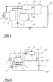
- FIG. 1 is a block circuit diagram showing the interconnection between the major components of the present invention.
- FIG. 2 is an electrical schematic view of block 2 (the rectifier/voltage-doubler) and block 3 (the multiplying circuit) from FIG. 1.
- FIG. 3 is an electrical schematic view of block 4 (the low power oscillator) from FIG. 1
- FIG. 4 is an electrical schematic view of block 5 (the amplifier) from FIG. 1.
- FIG. 5 shows the entire electrical schematic diagram of the ballast circuit of the present invention.
- FIG. 1 there is shown the electrical connections between the major block-diagram components which constitute the entire invention.
- the network AC source 1 has power leads to both the rectifier/voltage-doubler 2 and the multiplier circuit 3.
- the multiplier circuit 3 serves as a voltage multiplier during the ignition stage of the lamp 6.
- the output from the rectifier/voltage-doubler 2 leads both into the multiplier circuit 3 and the low power oscillator 4.
- the outputs from the multiplier circuit 3 and low power oscillator 4 lead into the amplifier 5, which feeds the lamp 6.
- the invention basically functions in two stages. First, it permits the gaseous discharge lamp to be ignited using a high frequency/high voltage signal. Second, once the lamp is lit, a switch to DC current occurs, which maintains the lamp in a stable, lit condition.
- the rectifier/voltage-doubler 2 is made up of diodes 9, 10, 11 and 12 , and capacitors 13 and 14.
- network AC source 1 energizes the entire circuit with voltage E in
- the rectifier/voltage-doubler 2 outputs at node 200 a DC current having voltage 2 ⁇ 2 E in with a 60 Hz ridge caused by the network AC source 1.
- Capacitor 19 serves to filter out these 60 Hz ridges in the signal coming from the rectifier/voltage-doubler 2 before such signal enters the low power oscillator 4.
- the output from the rectifier/voltage-doubler 2 connects at node 200 to multiplier circuit 3.
- Multiplier circuit 3 elevates the voltage used to ignite the lamp 6 to a level of 3 ⁇ 2 E in at node 300.
- Multiplier circuit 3 elevates the ignition supply voltage by allowing capacitor 15 to be quickly charged via diodes 18 and 16 during the negative cycle of the network AC source 1.
- Capacitor 15 is charged up to a level of 3 ⁇ 2 E in since this is the net potential between the negative cycle of the network AC source 1 (- ⁇ 2 E in ) and the value at node 300 (2 ⁇ 2 E in ).
- the capacitor 15 discharges the stored 3 ⁇ 2 E in through resistor 17 which, given the minimal current during the ignition stage, presents a negligible drop in potential across itself thereby effectively presenting 3 ⁇ 2 E in at node 300.
- FIG. 3 presents the circuitry and electrical components of the low power oscillator 4, including transistors 26 and 27, capacitors 24 and 25 , and resistors 21, 22, 23 and 20.
- Low power oscillator 4 is a square wave oscillator which receives the filtered DC signal at node 200 (2 ⁇ 2 E in ) and outputs a 2 ⁇ 2 E in high frequency signal of 25 kHz at node 400. This output oscillates between 0 and 2 ⁇ 2 E in , thus giving an average output of ⁇ 2 E in .
- FIG. 4 shows the amplifier 5 which includes capacitors 28, 29, 30 and 31 and diodes 32, 33, 34 and 35.
- Amplifier 5 receives as its input both the signal at node 300 (the output from multiplier circuit 3 ) with a voltage of 3 ⁇ 2 E in , and the 25 kHz high frequency signal from node 400 (the output from the low power oscillator 4) .
- Amplifier 5 takes the average voltage from these two signals, 2 ⁇ 2 E in , and multiplies it by a multiplication factor of G.
- the value of G is equal to 4, thus producing a signal having a voltage of 8 ⁇ 2 E in (minus losses) and a 25 kHz frequency.
- This signal is then fed to the lamp 6 at node 500 which ionizes the gas within and ignites the lamp.
- No filament is necessary within the lamp as the ignition depends only on the photoemission of ions, and not on thermoionic or field emission. All that is needed to ignite and maintain the lamp lit is a conductor, preferably at each end of the lamp, in intimate contact with the gas within the lamp.
- the entire ballast circuit may be observed. Once the lamp 6 is ignited, the impedance presented by it drops dramatically, which permits the entire circuit to switch over from a high frequency ignition current to a DC maintenance current (the current used to maintain the lamp lit). In order for this switch to take place, the following changes in the circuit occur automatically.
- the drop in impedance of lamp 6 instantly increases the current running through the entire circuit. This increase in current creates a larger voltage drop across capacitor 37, which significantly lowers the voltage supply (E in ) to the rectifier/voltage doubler 2, which consequently lowers the voltage supply to the low power oscillator 4. This voltage drop puts it at a level where the low power oscillator 4 ceases to work (i.e. cease oscillating).
- This voltage drop at node 200 is further increased by the fact that the dielectric loss in capacitors 13 and 14 is increased such that these components can no longer maintain their charges to quite "double" the voltage.
- This effect causes a DC current to flow through node 400, creates an open circuit across capacitor 28, and isolates amplifier 5 from the low oscillator.
- the voltage drop across resistor 17 in multiplier circuit 3 becomes significant enough such that the voltage at node 200 (2 ⁇ 2 E in ).
- This difference causes diode 18 to become forward biased which, in turn, allows the DC current ouput at node 200 to flow through diode 18 and into the amplifier 5 . Because this current is DC, capacitors 29, 30 and 31 create open circuits, which requires that the DC current flow through diodes 32, 33, 34 and 35, and then to the lamp 6 , hence providing a DC maintenance current.
- ballast circuit The following chart gives illustrative values of the circuit elements for use in the ballast circuit of the present invention.
- This particular ballast circuit is used, ideally, with a 40W fluorescent lamp and a 120V, 60Hz AC source. All diodes are type 1N4004 and both transistors ( 26 and 27 ) are type C2611.
- Capacitor 37 18 ⁇ F @ 250V Capacitor 13 4.7 ⁇ F @ 250V Capacitor 14 4.7 ⁇ @ 250V Capacitor 19 22 ⁇ F @ 250V Capacitor 15 3.3 ⁇ F @ 350V Capacitor 28 0.15 ⁇ F @ 250V Capacitor 29 0.15 ⁇ F @ 250V Capacitor 30 0.15 ⁇ F @ 250V Capacitor 31 0.15 ⁇ F @ 250V Capacitor 24 0.033 ⁇ F @ 250V Capacitor 25 0.0027 ⁇ F @ 250V Resistor 17 3.9 k ⁇ @ 1W Resistor 22 1 M ⁇ @ 0.5W Resistor 23 1 M ⁇ @ 0.5W Resistor 21 22 k ⁇ @ 1W Resistor 20 100 k ⁇ @ 0.5W
- the power required for ignition of the lamp 6 is less than 1 watt. This minimal power requirement is primarily attributable to the fact that the low power oscillator 4 sees a high impedance load at its output, which permits its supply current to be quite low (around the order of 8 milliamps).
- the DC maintenance current increases to approximately 200 milliamps and the voltage potential E in across rectifier/voltage-doubler 2 drops from approximately 116 volts to approximately 27 volts. This drop results in a DC maintenance voltage of 2 ⁇ 2 E in , or approximately 75 volts.
- the ballast circuit of the present invention only requires 24 to 27 watts.
- the present invention solves the problem of anode darkening and mercury migration by limiting the amount of the maintenance current to the bare minimum required to maintain the lamp lit.
- Johnson U.S. Patent No. 4,260,932 teaches that the amount of charge accumulation resultant from a unidirectional current is dependent upon the velocity of the electrons and negative ions within the lamp and upon the amount of current flow (density of electrons and negative ions) within the lamp.
- the velocity of the charged electrons and ions is, in turn, primarily dependent upon the discharge length of the lamp, (this determining the time period during which the negatively charged particles are accelerated), and accelerating voltage (operating voltage) of the lamp.
- the current used limits the amount of electron and ion bombardment to a minimum, allowing the lamp to recuperate from minor migration during the time it is turned off.
Landscapes
- Circuit Arrangements For Discharge Lamps (AREA)
- Steering Control In Accordance With Driving Conditions (AREA)
Applications Claiming Priority (2)
| Application Number | Priority Date | Filing Date | Title |
|---|---|---|---|
| CO93414977A CO4180415A1 (es) | 1993-10-21 | 1993-10-21 | Metodo para el encendido de lamparas fluorescentes con o sin filamento |
| CL93414977 | 1993-10-21 |
Publications (3)
| Publication Number | Publication Date |
|---|---|
| EP0650312A2 true EP0650312A2 (de) | 1995-04-26 |
| EP0650312A3 EP0650312A3 (de) | 1996-03-20 |
| EP0650312B1 EP0650312B1 (de) | 2000-07-12 |
Family
ID=5331354
Family Applications (1)
| Application Number | Title | Priority Date | Filing Date |
|---|---|---|---|
| EP94202932A Expired - Lifetime EP0650312B1 (de) | 1993-10-21 | 1994-10-11 | Schaltung zum Betreiben einer Leuchtstofflampe |
Country Status (8)
| Country | Link |
|---|---|
| EP (1) | EP0650312B1 (de) |
| JP (1) | JPH07263153A (de) |
| KR (1) | KR100233693B1 (de) |
| CN (1) | CN1106604A (de) |
| AT (1) | ATE194747T1 (de) |
| BR (1) | BR9404212A (de) |
| CO (1) | CO4180415A1 (de) |
| DE (1) | DE69425217D1 (de) |
Cited By (4)
| Publication number | Priority date | Publication date | Assignee | Title |
|---|---|---|---|---|
| WO1996029846A1 (en) * | 1995-03-22 | 1996-09-26 | United Light Electronics Ltd | Power supply for light sources, particularly for the quick ignition of fluorescent lamps and the like |
| EP0748147A3 (de) * | 1995-06-05 | 1998-01-28 | Francisco Javier Velasco Valcke | Elektronisches Vorschaltgerät für Leuchtstofflampen |
| EP1023818A4 (de) * | 1997-07-25 | 2003-08-13 | Jorge M Parra | Niederspannungsleuchtstofflampensystem und verfahren ohne glühstarter oder vorschaltgerät |
| WO2022264169A1 (en) * | 2021-06-17 | 2022-12-22 | Narsimha Chary Mandaji | A device with customized integrated electronic circuit for destroying pathogens |
Families Citing this family (2)
| Publication number | Priority date | Publication date | Assignee | Title |
|---|---|---|---|---|
| CN100525570C (zh) * | 2004-11-16 | 2009-08-05 | 蒋中为 | 一种气体放电灯的快速启动器 |
| CN121417671A (zh) * | 2025-12-29 | 2026-01-27 | 陕西中科天地航空模块有限公司 | 一种超低输入电压升压电路 |
Family Cites Families (1)
| Publication number | Priority date | Publication date | Assignee | Title |
|---|---|---|---|---|
| FR2645393B3 (fr) * | 1989-04-03 | 1991-07-05 | Ferrero Alexandre | Dispositif autonome d'eclairage a tube a decharge gazeuse |
-
1993
- 1993-10-21 CO CO93414977A patent/CO4180415A1/es unknown
-
1994
- 1994-10-11 EP EP94202932A patent/EP0650312B1/de not_active Expired - Lifetime
- 1994-10-11 AT AT94202932T patent/ATE194747T1/de not_active IP Right Cessation
- 1994-10-11 DE DE69425217T patent/DE69425217D1/de not_active Expired - Lifetime
- 1994-10-19 JP JP6278541A patent/JPH07263153A/ja active Pending
- 1994-10-20 KR KR1019940026892A patent/KR100233693B1/ko not_active Expired - Fee Related
- 1994-10-21 BR BR9404212A patent/BR9404212A/pt not_active Application Discontinuation
- 1994-10-21 CN CN94117199A patent/CN1106604A/zh active Pending
Cited By (5)
| Publication number | Priority date | Publication date | Assignee | Title |
|---|---|---|---|---|
| WO1996029846A1 (en) * | 1995-03-22 | 1996-09-26 | United Light Electronics Ltd | Power supply for light sources, particularly for the quick ignition of fluorescent lamps and the like |
| US5920153A (en) * | 1995-03-22 | 1999-07-06 | United Light Electronics Ltd. | Power supply for light sources, particularly for the quick ignition of fluorescent lamps and the like |
| EP0748147A3 (de) * | 1995-06-05 | 1998-01-28 | Francisco Javier Velasco Valcke | Elektronisches Vorschaltgerät für Leuchtstofflampen |
| EP1023818A4 (de) * | 1997-07-25 | 2003-08-13 | Jorge M Parra | Niederspannungsleuchtstofflampensystem und verfahren ohne glühstarter oder vorschaltgerät |
| WO2022264169A1 (en) * | 2021-06-17 | 2022-12-22 | Narsimha Chary Mandaji | A device with customized integrated electronic circuit for destroying pathogens |
Also Published As
| Publication number | Publication date |
|---|---|
| KR960016643A (ko) | 1996-05-22 |
| EP0650312B1 (de) | 2000-07-12 |
| DE69425217D1 (de) | 2000-08-17 |
| CO4180415A1 (es) | 1995-06-07 |
| ATE194747T1 (de) | 2000-07-15 |
| KR100233693B1 (ko) | 1999-12-01 |
| EP0650312A3 (de) | 1996-03-20 |
| JPH07263153A (ja) | 1995-10-13 |
| BR9404212A (pt) | 1995-06-27 |
| CN1106604A (zh) | 1995-08-09 |
Similar Documents
| Publication | Publication Date | Title |
|---|---|---|
| US5686799A (en) | Ballast circuit for compact fluorescent lamp | |
| US5866993A (en) | Three-way dimming ballast circuit with passive power factor correction | |
| US6348769B1 (en) | Electronic ballast | |
| JP3797079B2 (ja) | 放電灯点灯装置 | |
| WO1996010898A3 (en) | Improvements in ballast circuit for fluorescent lamps | |
| US5710487A (en) | Ballast circuit for gaseous discharge lamps without inductive electrical components or filaments | |
| US6091208A (en) | Lamp ignitor for starting conventional hid lamps and for starting and restarting hid lamps with hot restrike capability | |
| EP0150536B1 (de) | Vorschaltadapter für den Betrieb von Leuchtstofflampen | |
| US5345148A (en) | DC-AC converter for igniting and supplying a gas discharge lamp | |
| US6819063B2 (en) | Sensing voltage for fluorescent lamp protection | |
| JPH06188091A (ja) | 放電灯点弧及び点灯回路配置 | |
| US5680016A (en) | Transformerless electronic ballast for gaseous discharge lamps | |
| EP0650312B1 (de) | Schaltung zum Betreiben einer Leuchtstofflampe | |
| US6118227A (en) | High frequency electronic drive circuits for fluorescent lamps | |
| US3890540A (en) | Apparatus for operating gaseous discharge lamps on direct current from a source of alternating current | |
| US4876485A (en) | Ballast for ionic conduction lamps | |
| US5057752A (en) | Circuit arrangement for igniting and operating gas-discharge lamps | |
| US4463285A (en) | DC Ballasting means for fluorescent lamps | |
| US5444334A (en) | System for starting a high intensity discharge lamp | |
| US4475062A (en) | Economy device for fluorescent lighting fixtures | |
| CA1232318A (en) | High intensity discharge lamp igniting device | |
| GB2146185A (en) | Lighting system | |
| US6696791B2 (en) | Method for starting a discharge lamp | |
| EP0011508B1 (de) | Verfahren zur Ermittlung von Bauteilenwerten für eine Steuerschaltung für eine Gasentladungslampe | |
| US4900986A (en) | Ballast circuit for starting fluorescent lamps |
Legal Events
| Date | Code | Title | Description |
|---|---|---|---|
| PUAI | Public reference made under article 153(3) epc to a published international application that has entered the european phase |
Free format text: ORIGINAL CODE: 0009012 |
|
| AK | Designated contracting states |
Kind code of ref document: A2 Designated state(s): AT BE CH DE DK ES FR GB GR IE IT LI NL PT SE |
|
| PUAL | Search report despatched |
Free format text: ORIGINAL CODE: 0009013 |
|
| AK | Designated contracting states |
Kind code of ref document: A3 Designated state(s): AT BE CH DE DK ES FR GB GR IE IT LI NL PT SE |
|
| 17P | Request for examination filed |
Effective date: 19960726 |
|
| R17P | Request for examination filed (corrected) |
Effective date: 19961121 |
|
| 17Q | First examination report despatched |
Effective date: 19981222 |
|
| GRAG | Despatch of communication of intention to grant |
Free format text: ORIGINAL CODE: EPIDOS AGRA |
|
| GRAG | Despatch of communication of intention to grant |
Free format text: ORIGINAL CODE: EPIDOS AGRA |
|
| GRAH | Despatch of communication of intention to grant a patent |
Free format text: ORIGINAL CODE: EPIDOS IGRA |
|
| GRAH | Despatch of communication of intention to grant a patent |
Free format text: ORIGINAL CODE: EPIDOS IGRA |
|
| GRAA | (expected) grant |
Free format text: ORIGINAL CODE: 0009210 |
|
| AK | Designated contracting states |
Kind code of ref document: B1 Designated state(s): AT BE CH DE DK ES FR GB GR IE IT LI NL PT SE |
|
| PG25 | Lapsed in a contracting state [announced via postgrant information from national office to epo] |
Ref country code: NL Free format text: LAPSE BECAUSE OF FAILURE TO SUBMIT A TRANSLATION OF THE DESCRIPTION OR TO PAY THE FEE WITHIN THE PRESCRIBED TIME-LIMIT Effective date: 20000712 Ref country code: LI Free format text: LAPSE BECAUSE OF FAILURE TO SUBMIT A TRANSLATION OF THE DESCRIPTION OR TO PAY THE FEE WITHIN THE PRESCRIBED TIME-LIMIT Effective date: 20000712 Ref country code: IT Free format text: LAPSE BECAUSE OF FAILURE TO SUBMIT A TRANSLATION OF THE DESCRIPTION OR TO PAY THE FEE WITHIN THE PRE;WARNING: LAPSES OF ITALIAN PATENTS WITH EFFECTIVE DATE BEFORE 2007 MAY HAVE OCCURRED AT ANY TIME BEFORE 2007. THE CORRECT EFFECTIVE DATE MAY BE DIFFERENT FROM THE ONE RECORDED.SCRIBED TIME-LIMIT Effective date: 20000712 Ref country code: GR Free format text: LAPSE BECAUSE OF NON-PAYMENT OF DUE FEES Effective date: 20000712 Ref country code: FR Free format text: LAPSE BECAUSE OF FAILURE TO SUBMIT A TRANSLATION OF THE DESCRIPTION OR TO PAY THE FEE WITHIN THE PRESCRIBED TIME-LIMIT Effective date: 20000712 Ref country code: ES Free format text: THE PATENT HAS BEEN ANNULLED BY A DECISION OF A NATIONAL AUTHORITY Effective date: 20000712 Ref country code: CH Free format text: LAPSE BECAUSE OF FAILURE TO SUBMIT A TRANSLATION OF THE DESCRIPTION OR TO PAY THE FEE WITHIN THE PRESCRIBED TIME-LIMIT Effective date: 20000712 Ref country code: BE Free format text: LAPSE BECAUSE OF FAILURE TO SUBMIT A TRANSLATION OF THE DESCRIPTION OR TO PAY THE FEE WITHIN THE PRESCRIBED TIME-LIMIT Effective date: 20000712 Ref country code: AT Free format text: LAPSE BECAUSE OF FAILURE TO SUBMIT A TRANSLATION OF THE DESCRIPTION OR TO PAY THE FEE WITHIN THE PRESCRIBED TIME-LIMIT Effective date: 20000712 |
|
| REF | Corresponds to: |
Ref document number: 194747 Country of ref document: AT Date of ref document: 20000715 Kind code of ref document: T |
|
| REG | Reference to a national code |
Ref country code: CH Ref legal event code: EP |
|
| REG | Reference to a national code |
Ref country code: IE Ref legal event code: FG4D |
|
| REF | Corresponds to: |
Ref document number: 69425217 Country of ref document: DE Date of ref document: 20000817 |
|
| PG25 | Lapsed in a contracting state [announced via postgrant information from national office to epo] |
Ref country code: IE Free format text: LAPSE BECAUSE OF NON-PAYMENT OF DUE FEES Effective date: 20001011 |
|
| PG25 | Lapsed in a contracting state [announced via postgrant information from national office to epo] |
Ref country code: SE Free format text: LAPSE BECAUSE OF FAILURE TO SUBMIT A TRANSLATION OF THE DESCRIPTION OR TO PAY THE FEE WITHIN THE PRESCRIBED TIME-LIMIT Effective date: 20001012 Ref country code: PT Free format text: LAPSE BECAUSE OF FAILURE TO SUBMIT A TRANSLATION OF THE DESCRIPTION OR TO PAY THE FEE WITHIN THE PRESCRIBED TIME-LIMIT Effective date: 20001012 Ref country code: GB Free format text: LAPSE BECAUSE OF NON-PAYMENT OF DUE FEES Effective date: 20001012 Ref country code: DK Free format text: LAPSE BECAUSE OF FAILURE TO SUBMIT A TRANSLATION OF THE DESCRIPTION OR TO PAY THE FEE WITHIN THE PRESCRIBED TIME-LIMIT Effective date: 20001012 |
|
| PG25 | Lapsed in a contracting state [announced via postgrant information from national office to epo] |
Ref country code: DE Free format text: LAPSE BECAUSE OF FAILURE TO SUBMIT A TRANSLATION OF THE DESCRIPTION OR TO PAY THE FEE WITHIN THE PRESCRIBED TIME-LIMIT Effective date: 20001013 |
|
| NLV1 | Nl: lapsed or annulled due to failure to fulfill the requirements of art. 29p and 29m of the patents act | ||
| EN | Fr: translation not filed | ||
| REG | Reference to a national code |
Ref country code: CH Ref legal event code: PL |
|
| PLBE | No opposition filed within time limit |
Free format text: ORIGINAL CODE: 0009261 |
|
| STAA | Information on the status of an ep patent application or granted ep patent |
Free format text: STATUS: NO OPPOSITION FILED WITHIN TIME LIMIT |
|
| GBPC | Gb: european patent ceased through non-payment of renewal fee |
Effective date: 20001012 |
|
| 26N | No opposition filed | ||
| REG | Reference to a national code |
Ref country code: IE Ref legal event code: MM4A |