EP0650564B1 - Ensemble boite de vitesses a disposer entre un moteur d'entrainement et un recepteur - Google Patents
Ensemble boite de vitesses a disposer entre un moteur d'entrainement et un recepteur Download PDFInfo
- Publication number
- EP0650564B1 EP0650564B1 EP93914693A EP93914693A EP0650564B1 EP 0650564 B1 EP0650564 B1 EP 0650564B1 EP 93914693 A EP93914693 A EP 93914693A EP 93914693 A EP93914693 A EP 93914693A EP 0650564 B1 EP0650564 B1 EP 0650564B1
- Authority
- EP
- European Patent Office
- Prior art keywords
- transmission
- hydrostatic transmission
- unit according
- transmission unit
- hydrostatic
- Prior art date
- Legal status (The legal status is an assumption and is not a legal conclusion. Google has not performed a legal analysis and makes no representation as to the accuracy of the status listed.)
- Expired - Lifetime
Links
- 230000037431 insertion Effects 0.000 title 1
- 238000003780 insertion Methods 0.000 title 1
- 230000005540 biological transmission Effects 0.000 claims abstract description 121
- 230000002706 hydrostatic effect Effects 0.000 claims abstract description 52
- 230000001360 synchronised effect Effects 0.000 claims abstract description 15
- 238000000034 method Methods 0.000 claims abstract description 7
- 238000012544 monitoring process Methods 0.000 claims abstract description 7
- 230000008569 process Effects 0.000 claims abstract description 7
- 238000006073 displacement reaction Methods 0.000 claims description 6
- 230000006870 function Effects 0.000 description 11
- 238000002485 combustion reaction Methods 0.000 description 5
- 230000009467 reduction Effects 0.000 description 5
- 238000010276 construction Methods 0.000 description 4
- 230000001105 regulatory effect Effects 0.000 description 4
- 230000008859 change Effects 0.000 description 3
- 238000006243 chemical reaction Methods 0.000 description 3
- 230000002349 favourable effect Effects 0.000 description 3
- 238000010586 diagram Methods 0.000 description 2
- 238000005516 engineering process Methods 0.000 description 2
- 230000009347 mechanical transmission Effects 0.000 description 2
- 230000002441 reversible effect Effects 0.000 description 2
- 230000001133 acceleration Effects 0.000 description 1
- 230000006978 adaptation Effects 0.000 description 1
- 239000000969 carrier Substances 0.000 description 1
- 238000011217 control strategy Methods 0.000 description 1
- 230000008878 coupling Effects 0.000 description 1
- 238000010168 coupling process Methods 0.000 description 1
- 238000005859 coupling reaction Methods 0.000 description 1
- 238000004519 manufacturing process Methods 0.000 description 1
- 230000007363 regulatory process Effects 0.000 description 1
Images

Classifications
-
- F—MECHANICAL ENGINEERING; LIGHTING; HEATING; WEAPONS; BLASTING
- F16—ENGINEERING ELEMENTS AND UNITS; GENERAL MEASURES FOR PRODUCING AND MAINTAINING EFFECTIVE FUNCTIONING OF MACHINES OR INSTALLATIONS; THERMAL INSULATION IN GENERAL
- F16H—GEARING
- F16H61/00—Control functions within control units of change-speed- or reversing-gearings for conveying rotary motion ; Control of exclusively fluid gearing, friction gearing, gearings with endless flexible members or other particular types of gearing
- F16H61/38—Control of exclusively fluid gearing
- F16H61/40—Control of exclusively fluid gearing hydrostatic
- F16H61/46—Automatic regulation in accordance with output requirements
- F16H61/472—Automatic regulation in accordance with output requirements for achieving a target output torque
-
- F—MECHANICAL ENGINEERING; LIGHTING; HEATING; WEAPONS; BLASTING
- F16—ENGINEERING ELEMENTS AND UNITS; GENERAL MEASURES FOR PRODUCING AND MAINTAINING EFFECTIVE FUNCTIONING OF MACHINES OR INSTALLATIONS; THERMAL INSULATION IN GENERAL
- F16H—GEARING
- F16H47/00—Combinations of mechanical gearing with fluid clutches or fluid gearing
- F16H47/02—Combinations of mechanical gearing with fluid clutches or fluid gearing the fluid gearing being of the volumetric type
-
- F—MECHANICAL ENGINEERING; LIGHTING; HEATING; WEAPONS; BLASTING
- F16—ENGINEERING ELEMENTS AND UNITS; GENERAL MEASURES FOR PRODUCING AND MAINTAINING EFFECTIVE FUNCTIONING OF MACHINES OR INSTALLATIONS; THERMAL INSULATION IN GENERAL
- F16H—GEARING
- F16H61/00—Control functions within control units of change-speed- or reversing-gearings for conveying rotary motion ; Control of exclusively fluid gearing, friction gearing, gearings with endless flexible members or other particular types of gearing
- F16H61/04—Smoothing ratio shift
- F16H61/0403—Synchronisation before shifting
-
- F—MECHANICAL ENGINEERING; LIGHTING; HEATING; WEAPONS; BLASTING
- F16—ENGINEERING ELEMENTS AND UNITS; GENERAL MEASURES FOR PRODUCING AND MAINTAINING EFFECTIVE FUNCTIONING OF MACHINES OR INSTALLATIONS; THERMAL INSULATION IN GENERAL
- F16H—GEARING
- F16H59/00—Control inputs to control units of change-speed- or reversing-gearings for conveying rotary motion
- F16H59/68—Inputs being a function of gearing status
- F16H2059/6838—Sensing gearing status of hydrostatic transmissions
- F16H2059/6853—Sensing gearing status of hydrostatic transmissions the state of the transmission units, i.e. motor or pump capacity, e.g. for controlled shifting of range gear
-
- F—MECHANICAL ENGINEERING; LIGHTING; HEATING; WEAPONS; BLASTING
- F16—ENGINEERING ELEMENTS AND UNITS; GENERAL MEASURES FOR PRODUCING AND MAINTAINING EFFECTIVE FUNCTIONING OF MACHINES OR INSTALLATIONS; THERMAL INSULATION IN GENERAL
- F16H—GEARING
- F16H59/00—Control inputs to control units of change-speed- or reversing-gearings for conveying rotary motion
- F16H59/68—Inputs being a function of gearing status
- F16H2059/6838—Sensing gearing status of hydrostatic transmissions
- F16H2059/6861—Sensing gearing status of hydrostatic transmissions the pressures, e.g. high, low or differential pressures
-
- F—MECHANICAL ENGINEERING; LIGHTING; HEATING; WEAPONS; BLASTING
- F16—ENGINEERING ELEMENTS AND UNITS; GENERAL MEASURES FOR PRODUCING AND MAINTAINING EFFECTIVE FUNCTIONING OF MACHINES OR INSTALLATIONS; THERMAL INSULATION IN GENERAL
- F16H—GEARING
- F16H59/00—Control inputs to control units of change-speed- or reversing-gearings for conveying rotary motion
- F16H59/68—Inputs being a function of gearing status
- F16H2059/6838—Sensing gearing status of hydrostatic transmissions
- F16H2059/6876—Sensing gearing status of hydrostatic transmissions the motor speed
-
- F—MECHANICAL ENGINEERING; LIGHTING; HEATING; WEAPONS; BLASTING
- F16—ENGINEERING ELEMENTS AND UNITS; GENERAL MEASURES FOR PRODUCING AND MAINTAINING EFFECTIVE FUNCTIONING OF MACHINES OR INSTALLATIONS; THERMAL INSULATION IN GENERAL
- F16H—GEARING
- F16H59/00—Control inputs to control units of change-speed- or reversing-gearings for conveying rotary motion
- F16H59/14—Inputs being a function of torque or torque demand
- F16H59/26—Inputs being a function of torque or torque demand dependent on pressure
-
- F—MECHANICAL ENGINEERING; LIGHTING; HEATING; WEAPONS; BLASTING
- F16—ENGINEERING ELEMENTS AND UNITS; GENERAL MEASURES FOR PRODUCING AND MAINTAINING EFFECTIVE FUNCTIONING OF MACHINES OR INSTALLATIONS; THERMAL INSULATION IN GENERAL
- F16H—GEARING
- F16H59/00—Control inputs to control units of change-speed- or reversing-gearings for conveying rotary motion
- F16H59/68—Inputs being a function of gearing status
- F16H59/70—Inputs being a function of gearing status dependent on the ratio established
-
- F—MECHANICAL ENGINEERING; LIGHTING; HEATING; WEAPONS; BLASTING
- F16—ENGINEERING ELEMENTS AND UNITS; GENERAL MEASURES FOR PRODUCING AND MAINTAINING EFFECTIVE FUNCTIONING OF MACHINES OR INSTALLATIONS; THERMAL INSULATION IN GENERAL
- F16H—GEARING
- F16H61/00—Control functions within control units of change-speed- or reversing-gearings for conveying rotary motion ; Control of exclusively fluid gearing, friction gearing, gearings with endless flexible members or other particular types of gearing
- F16H61/02—Control functions within control units of change-speed- or reversing-gearings for conveying rotary motion ; Control of exclusively fluid gearing, friction gearing, gearings with endless flexible members or other particular types of gearing characterised by the signals used
- F16H61/0202—Control functions within control units of change-speed- or reversing-gearings for conveying rotary motion ; Control of exclusively fluid gearing, friction gearing, gearings with endless flexible members or other particular types of gearing characterised by the signals used the signals being electric
- F16H61/0204—Control functions within control units of change-speed- or reversing-gearings for conveying rotary motion ; Control of exclusively fluid gearing, friction gearing, gearings with endless flexible members or other particular types of gearing characterised by the signals used the signals being electric for gearshift control, e.g. control functions for performing shifting or generation of shift signal
- F16H61/0206—Layout of electro-hydraulic control circuits, e.g. arrangement of valves
-
- F—MECHANICAL ENGINEERING; LIGHTING; HEATING; WEAPONS; BLASTING
- F16—ENGINEERING ELEMENTS AND UNITS; GENERAL MEASURES FOR PRODUCING AND MAINTAINING EFFECTIVE FUNCTIONING OF MACHINES OR INSTALLATIONS; THERMAL INSULATION IN GENERAL
- F16H—GEARING
- F16H61/00—Control functions within control units of change-speed- or reversing-gearings for conveying rotary motion ; Control of exclusively fluid gearing, friction gearing, gearings with endless flexible members or other particular types of gearing
- F16H61/38—Control of exclusively fluid gearing
- F16H61/40—Control of exclusively fluid gearing hydrostatic
- F16H61/42—Control of exclusively fluid gearing hydrostatic involving adjustment of a pump or motor with adjustable output or capacity
- F16H61/421—Motor capacity control by electro-hydraulic control means, e.g. using solenoid valves
-
- F—MECHANICAL ENGINEERING; LIGHTING; HEATING; WEAPONS; BLASTING
- F16—ENGINEERING ELEMENTS AND UNITS; GENERAL MEASURES FOR PRODUCING AND MAINTAINING EFFECTIVE FUNCTIONING OF MACHINES OR INSTALLATIONS; THERMAL INSULATION IN GENERAL
- F16H—GEARING
- F16H61/00—Control functions within control units of change-speed- or reversing-gearings for conveying rotary motion ; Control of exclusively fluid gearing, friction gearing, gearings with endless flexible members or other particular types of gearing
- F16H61/38—Control of exclusively fluid gearing
- F16H61/40—Control of exclusively fluid gearing hydrostatic
- F16H61/42—Control of exclusively fluid gearing hydrostatic involving adjustment of a pump or motor with adjustable output or capacity
- F16H61/431—Pump capacity control by electro-hydraulic control means, e.g. using solenoid valves
-
- Y—GENERAL TAGGING OF NEW TECHNOLOGICAL DEVELOPMENTS; GENERAL TAGGING OF CROSS-SECTIONAL TECHNOLOGIES SPANNING OVER SEVERAL SECTIONS OF THE IPC; TECHNICAL SUBJECTS COVERED BY FORMER USPC CROSS-REFERENCE ART COLLECTIONS [XRACs] AND DIGESTS
- Y10—TECHNICAL SUBJECTS COVERED BY FORMER USPC
- Y10T—TECHNICAL SUBJECTS COVERED BY FORMER US CLASSIFICATION
- Y10T74/00—Machine element or mechanism
- Y10T74/19—Gearing
- Y10T74/19149—Gearing with fluid drive
- Y10T74/19153—Condition responsive control
-
- Y—GENERAL TAGGING OF NEW TECHNOLOGICAL DEVELOPMENTS; GENERAL TAGGING OF CROSS-SECTIONAL TECHNOLOGIES SPANNING OVER SEVERAL SECTIONS OF THE IPC; TECHNICAL SUBJECTS COVERED BY FORMER USPC CROSS-REFERENCE ART COLLECTIONS [XRACs] AND DIGESTS
- Y10—TECHNICAL SUBJECTS COVERED BY FORMER USPC
- Y10T—TECHNICAL SUBJECTS COVERED BY FORMER US CLASSIFICATION
- Y10T74/00—Machine element or mechanism
- Y10T74/19—Gearing
- Y10T74/19149—Gearing with fluid drive
- Y10T74/19158—Gearing with fluid drive with one or more controllers for gearing, fluid drive, or clutch
- Y10T74/19163—Gearing with fluid drive with one or more controllers for gearing, fluid drive, or clutch with interrelated controls
Definitions
- the invention relates to a gear unit according to the preamble of claim 1.
- a manual transmission between the drive motor and the consumer.
- One reason for this may be that the desired speeds for the consumer differ so significantly from the output speed of a given drive motor that a manual transmission must be provided.
- Another reason can be that certain consumers, such as vehicles and in particular construction vehicles, have specific wheel and chain drives, which is to be assumed when determining the drive motor.
- Another fundamental reason for the use of a manual transmission is that a manual transmission enables the function of the existing drive in favorable speed ranges of the drive motor, which is particularly the case when internal combustion engines and preferably diesel engines are used as the drive motor.
- construction machinery such as wheel loaders, earth pushers, excavators and the like, as well as municipal tractors and implement carriers are preferably driven by internal combustion engines, in particular diesel engines, whereby a drive which is independent of a stationary energy source and which is powerful and can be operated inexpensively is specified.
- a transmission unit of the type mentioned at the outset is described in DE 34 33 495 C2 for semi-automatic shifting and in DE 34 33 494 C2 for automatic shifting.
- These two transmission units each include an adjustable hydrostatic transmission and a powershift transmission, whereby the adjustability of the hydrostatic transmission is used in all cases to regulate the transmitted power with a power controller on the one hand and, on the other hand, for a gearshift operation, a speed adjustment predetermined by the gear stage to be shifted bring about.
- the speed is adjusted in the area of a clutch at the outlet of the hydrostatic transmission (DE 34 33 495 C2) or in the area of the clutch of the respective powershift stage (DE 34 33 495 C2), the output speed of the hydrostatic transmission being adjusted so that the speed is the same on the respective There is a clutch, after which it is switched smoothly. It is not absolutely necessary to change the speed of the drive motor, which in these known configurations is formed by an internal combustion engine.
- the invention has for its object to develop a gear unit of the type specified so that the effort for switching is reduced while ensuring a simple and inexpensive design.
- a particularly mechanically synchronized synchronizing device with a particularly mechanical manual transmission is used, which is offered as a standard version on the market in a large number of variations in terms of size and applications and is available at low cost and can also be switched in a simple manner.
- a targeted speed adjustment is eliminated for the shifting process.
- the invention is particularly suitable for drives of self-driving vehicles with a high conversion range.
- a closed or open circuit hydrostatic transmission can be used.
- a special clutch, in particular between the hydrostatic transmission and the manual transmission, is not required in the invention.
- the hydrostatic transmission is controlled or regulated in its load state in accordance with the specific data of the synchronizing devices used, whereby trouble-free and fast shifting is achieved with a simple and inexpensive design without the synchronized transmission being overloaded and therefore a trouble-free function and long life is guaranteed.
- the transmission unit according to the invention can be used for manual, semi-automatic or fully automatic shifting, both for upshifting or downshifting.
- a semi-automatic or fully automatic shifting device can be provided, with an adjusting device for the hydrostatic transmission and a shifting device for the gears of the manual transmission.
- Such a switching device can contain a computer or a processor which monitors the switching criteria and initiates the switching if the switching criteria are met.
- This is the permissible transferable working torque of the synchronizing devices of the manual transmission and the output torque of the hydrostatic transmission, which can be determined by monitoring the load state of the hydrostatic transmission.
- Monitoring the working pressure of the hydrostatic transmission a pressure gauge or pressure transducer, is preferably suitable for this purpose.
- the effective output torque can be determined or calculated from the respective pressure value, taking into account the existing gear setting and parameters.
- the respectively permissible transmissible working torque or the performance limits of the synchronizing devices of the manual transmission are known or to be determined. It is advantageous to specify this data in the control or regulating device of the switching device, for example by storing, since this data is fixed values with respect to the synchronized gearbox present in each case.
- the subclaims contain features that contribute to solving the problem and enable a satisfactory determination of the respective output torque of the hydrostatic transmission as well as its adjustment.
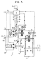
- the transmission unit 1 comprises an adjustable hydrostatic transmission 2 and a mechanically synchronized and thus inevitably functioning manual transmission 4 with two gear stages downstream of the latter in the direction of transmission (arrow 3), namely a first gear 5 and a second gear 6, whereby a reverse gear may be present, which is not shown for reasons of simplification.
- the gears 5, 6 are assigned a synchronizing device 7, each with a synchronizing ring 7a, 7b.
- the transmission 4 is e.g. mechanically and / or electrically functioning switching device 9 is assigned, which acts on the gears 5, 6 via the synchronizing device 7.
- the hydrostatic transmission 2 has a closed circuit 10 with a pressure line 11 and a low-pressure line 12, between which a hydraulic pump 13 and a hydraulic motor 14 are connected on the input side in the usual way. At least one of these two hydraulic parts (pump 13 or motor 14) can be adjusted with regard to its working or passage volume.
- the hydraulic pump 13 and the hydraulic motor 14 are each adjustable by means of an adjusting device 15a and 15b.
- a regulating or control device 16 is used, which executes the required gearshifts semi or fully automatically according to certain functional criteria.
- the control device 16 comprises, in particular, an electronic control unit 17, preferably with a microprocessor, which is connected by control lines 18, 19, 20 to the adjusting devices 15a, 15b and to the switching device 9 and signal lines 21, 22, 23 to function-specific transmitters of the transmission unit 1.
- the signal line 21 connects the control unit 17 to a pressure transducer 24, which is the working pressure of the hydrostatic transmission 2 determined in a manner known per se (pressure p) and converted into an electrical signal (voltage U or current I), which thus represents a design variable for the working pressure.
- the signal line 23 connects the control unit 17 to a tachometer 26 which sits on the shaft 27 connecting the hydrostatic transmission 2 to the manual transmission 4 and generates a signal n which corresponds to the output speed of the hydrostatic transmission 2 and can be fed to the control unit 17 by means of the signal line 23 is.
- the control line 19 and the signal line 22 are shown in dashed lines and thus indicated because they do not necessarily have to be present, for example when only the hydraulic pump 13 is adjustable.
- the pressure transducer 24 can be assigned to the hydraulic pump 13 or to the pressure line 11 or low-pressure line 12, in order to be able to detect the pressure present in each case.
- the adjustment devices 15a, 15b are adjustable beyond their zero position, as a result of which the direction of rotation of the hydrostatic transmission 2 is reversible and the pressure side also changes.
- the manual transmission 4 comprises two gear pairs 28a, 28b and 29a, 29b, each forming a gear 5, 6, which are mounted on two shafts 32, 33 which are rotatably mounted parallel to one another in the transmission housing 31 and of which the shaft 32 is connected to the hydraulic motor 14 as an input shaft is, while the shaft 33 is an output shaft.
- the gearwheels 28a, 29a are supported on the input shaft 32 by means of hollow shafts 34, 35.
- the synchronizing device 7 assigned to each gear 5, 6 or both gears can be of a conventional type.
- a synchronizer ring 36 is provided in each case, the conical surface 37 of which cooperates with the conical surface 38 of a driving ring 39 which is indirectly connected to the associated gear 28a, 29a.
- a common function ring 41 is assigned to the two synchronizer rings 36 approximately in the center, which is activated by the switching device 9 by means of a e.g.
- the functional ring 41 in an annular groove engaging linkage relative to the associated synchronizer ring 36 and driver ring 39 is displaceable, wherein the functional ring 41 axially acts on the associated synchronizer ring 36 and interacts with specially shaped coupling elements 42a, 42b with the associated driver ring 39.
- the functional ring 41 coaxially surrounds a central wedge ring 43 which is connected to the input shaft 32 in a rotationally fixed manner by means of a keyway connection 44.
- the first gear 5 In the shifted position (indicated) to the left of the functional ring 41, the first gear 5 is shifted, while in the shifted position of the functional ring 41 shifted to the right, the second gear 6 is engaged.
- a freewheel is present in the middle position of the functional ring 41.
- the control device 16 is assigned a selector switch 45 and by an active connection, e.g. Signal line 46 connected to the control unit 17.
- the desired gear shift can be preselected or initiated manually at the selector switch 45.
- the gear unit 1 is intended for the arrangement between a drive motor 47, which is preferably an internal combustion engine and in particular a diesel engine, and which is connected to the hydraulic pump 13, and a consumer 48 which is connected to the output shaft 33 of the gearbox 4 connected is.
- the transmission unit 1 according to the invention is particularly suitable with a drive motor in the form of an internal combustion engine, preferably a diesel engine, as a drive for vehicles, in particular Construction vehicles. In this way, a functional, robust and powerful transmission arrangement is achieved, which largely enables trouble-free shifting even under load conditions.
- An auxiliary pump 49 can be arranged between the indicated drive motor 47 and the hydrostatic transmission 2, which supplies a control pressure that can be used for the hydraulic control of adjustment or switching functions, for example control of the adjustment devices 15a, 15b by means of suitable hydraulic control elements.
- the function of the transmission unit 1, including the control device 16, is described below on the basis of a switching operation.
- a gear change is initiated by actuating the selector switch 45, whereby the gear shift can take place immediately or - if a tachometer 26 is present - the gear shift is only carried out when a speed is available at which the shift makes sense and is cheaper Speed range for the drive motor 47 is predetermined.
- the control unit 17 performing the monitoring function uses signals U or I and V2 to determine whether the output torque M of the hydrostatic transmission 2 is greater than the permissible transmissible working torque of the associated synchronizing device 7. If this output torque M is equal to or less than that than the working torque, the shifting of a higher or lower gear can be carried out immediately. If, on the other hand, the output torque M is greater than the working torque, then the adjusting device 15b of the hydraulic motor 14 is adjusted in the direction of a smaller throughput volume, that is to say pivoted back until the output torque V2 is equal to or less than the working torque. A control process or a regulating process can be used to carry out such an output torque reduction.
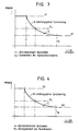
- the output torque M can be controlled so that it is always at the power limit of the associated synchronizing device 7, or an imaginary characteristic curve below the power limit can be controlled or adjusted.
- a characteristic e.g. the power limit can be stored in a memory of the electronic control unit 17. The definition of such a characteristic curve can be determined without problems in accordance with the known performance data of the synchronizing device.
- the gear shift is initiated or carried out when the output torque is at or below the power limit N, i.e. located in area S.
- the transmission ratio of the hydrostatic transmission 2 was changed or increased by adjusting the hydraulic motor 14 in order to reduce the output torque M. This is favorable because such an adjustment enables the output torque M to be influenced directly.
- the output speed of the hydrostatic transmission 2 increases, but this is irrelevant, since - as already explained at the beginning - there is no need to pay attention to an associated speed match, as far as a speed match of two rotating parts to be connected, here the associated synchronizing device, is concerned is. In the embodiment according to the invention, this speed adjustment is automatically carried out automatically by the synchronizing device 7.
- FIGS. 3 and 4 show the power limit of the synchronizing device 7 as curve N in each case in a coordinate system, the output speed n of the hydraulic motor 14 being plotted on the ordinate and the output torque M on the abscissa.
- FIG. 3 in which the curve of the power limit of the associated synchronizer ring 36 is illustrated when compared with a minimum working pressure p1 and a maximum working pressure p2, FIG. 4 shows the curve of the power limit of the synchronizer ring 36 on the basis of the minimum torque M1 and the maximum Torque M2 illustrates.
- the system pressure of the hydraulic circuit is designated by p x in FIG. 3
- the drag torque of the adjustable hydraulic motor 14 is illustrated by M x in FIG.
- the design limit of the hydraulic motor 14 is designated by g. It is advantageous to assign a pressure regulator to the hydraulic circuit, which sets a constant or variable working pressure in at least one partial area. Such a configuration ensures that, on the one hand, the working pressure does not drop below a predetermined value and, therefore, the working pressure does not have to be built up again in the event of a subsequent acceleration. On the other hand, pressure regulation compensates for pressure increases resulting from various reasons, which can affect the switching and the driving behavior.
- the gear unit 1 is designed in the sense of a so-called summation gear.
- the hydraulic circuit 10 has a parallel line section 10a, in which a further hydraulic motor 14a is arranged, which can be a constant motor or an adjusting motor, which is connected to the control unit 17 by a control line 19a and a signal line 22a in the above-described sense is.
- the gearbox 4 is assigned a gear section 4a with two parallel shafts 32a, 32b and the pre-extended shaft 32, which are connected to one another by gearwheels 50, 51, 52. This creates a gear branch that can be optionally switched on.
- a further synchronizing device 7c is arranged, which is used for connecting and synchronizing the transmission branch and is effective on one side.
- the transmission branch forms a synchronous load stage for the synchronous transmission 4.
- This variant makes it possible to reduce the output torque M by disabling part of the output torque M, here the hydraulic motor 14, by interrupting the drive connection between the hydraulic motor 14 and the manual transmission 4. which can be optionally carried out by the synchronizing device 7c.
- the working torque of the synchronizing device 7c is also taken into account when the hydraulic motor 14 is switched on, namely in that the output torque is adjusted by setting the hydraulic motor 14 in the direction of a smaller throughput volume such that the output torque is below the power limit of the associated synchronizing device 7c.
- the hydraulic motor 14a is a constant motor, it can be designed so that the output torque transmitted by it is always less than the working torque of the synchronizing device 7, that is, after the hydraulic motor 14 is switched off, the desired gear can be shifted immediately.
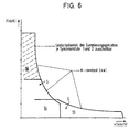
- FIG. 6 shows the example of a transmission design with constant power N with the synchronous stages 54, 55 of the synchronizing devices 7, 7c in a coordinate system, the ordinate of which is the speed and the abscissa of which is the driving force.
- the load shift portion of the summation gear is designated 56.
- the driving ranges or gears can be shifted while driving via the synchronized transmission 4.
- Each synchronized speed stage 5, 6 has a power shift stage.
- Standard gears can be used, making them cost-effective.
Landscapes
- Engineering & Computer Science (AREA)
- General Engineering & Computer Science (AREA)
- Mechanical Engineering (AREA)
- Control Of Transmission Device (AREA)
- Brushes (AREA)
- Massaging Devices (AREA)
- Control Of Fluid Gearings (AREA)
- Control Of Driving Devices And Active Controlling Of Vehicle (AREA)
- Packages (AREA)
- Arrangement Of Transmissions (AREA)
- Dry Shavers And Clippers (AREA)
- Gear-Shifting Mechanisms (AREA)
Claims (10)
- Unité de transmission (1) destinée à être placée entre un moteur d'entraînement (47) et un récepteur (48), constituée d'une transmission hydrostatique (2), réglable au Moyen d'un dispositif de réglage (15a, 15b), d'une boîte de vitesses mécanique (4) montée en aval de cette dernière, avec plusieurs rapports (5, 6) et d'un dispositif de commande pour le réglage de la transmission hydrostatique (2) au moyen du dispositif de réglage (15a, 15b) pour une opération de commutation, caractérisée en ce que la boîte de vitesses (4) est une boîte de vitesses synchrone avec dispositifs de synchronisation (7, 7a) pour les rapports (5, 6), en ce qu'au dispositif de commande (16) est associé un dispositif (U, V2) pour la mesure ou le contrôle du couple de rotation de sortie (M) de la transmission hydrostatique (2), et en ce que dans le cas où avant une opération de commutation, le couple de rotation de sortie (M) est supérieur au moment de travail du dispositif de synchronisation (7, 7a) correspondant, le dispositif de commande (16) règle un couple de rotation de sortie (M) sur la transmission hydrostatique (2), qui est égal ou inférieur au moment de travail du dispositif de synchronisation associé au rapport (6, 7) correspondant.
- Unité de transmission selon la revendication 1, caractérisée en ce que le dispositif de mesure ou de contrôle du couple de rotation de sortie (M) comporte un dispositif de mesure de pression déterminant la pression de travail de la transmission hydrostatique, qui produit un signal de commande correspondant pour le dispositif de commande (16).
- Unité de transmission selon la revendication 1 ou 2, caractérisée en ce que le dispositif de mesure ou de contrôle du couple de rotation de sortie (M) comporte un dispositif de mesure pour la détermination du volume du circuit ou débit (V2), en particulier dans le moteur hydraulique (14), qui produit un signal de commande correspondant pour le dispositif de commande (16).
- Unité de transmission selon l'une au moins des revendications précédentes, caractérisée en ce que la pompe hydraulique (13) et/ou le moteur hydraulique (14) sont réglables chacun au moyen du dispositif de réglage (15a, 15b).
- Unité de transmission selon la revendication 4, caractérisée en ce que le dispositif de mesure est un dispositif de mesure de distance ou d'angle (25) déterminant la distance de réglage ou l'angle de réglage.
- Unité de transmission selon l'une au moins des revendications précédentes, caractérisée en ce que il est prévu un dispositif de mesure de vitesse de rotation (26) déterminant la vitesse de rotation de sortie de la transmission hydrostatique (2) ou une vitesse de rotation correspondante, qui produit un signal de commande pour le dispositif de commande (16).
- Unité de transmission selon l'une au moins des revendications précédentes, caractérisée en ce que il est prévu un dispositif de commande (16, 17) semi-automatique ou entièrement automatique, de préférence électronique, qui est relié par des liaisons de commande ou des liaisons de signaux avec le ou les dispositifs de réglage (15a, 15b), le dispositif de mesure de pression, le dispositif de mesure du débit, le dispositif de mesure de vitesse de rotation et/ou un dispositif de commutation (9) pour la boîte de vitesses (4).
- Unité de transmission selon l'une au moins des revendications précédentes, caractérisée en ce que au dispositif de réglage (15a, 15b) pour la pompe hydraulique (13) et/ou le moteur hydraulique (14) est associé chaque fois un régulateur de pression, qui règle une pression de travail dans la transmission hydrostatique (2) de manière que son moment de sortie (11) soit égal ou inférieur au moment de travail du dispositif de synchronisation (7, 7a) correspondant.
- Unité de transmission selon l'une au moins des revendications précédentes, caractérisée en ce que la transmission hydrostatique (2) comporte plusieurs moteurs hydrauliques (14, 14a) sous la forme de moteurs constants et/ou de moteurs de réglage, une partie des moteurs hydrauliques (14) pouvant au choix être mis à l'arrêt.
- Unité de transmission selon la revendication 9, caractérisée en ce que dans la liaison de transmission entre un moteur hydraulique (14) et la boîte de vitesses (4) il est prévu une liaison de transmission détachable, avec un autre dispositif de synchronisation (7c) mécanique, de préférence sous la forme d'un rapport commutable avec un dispositif de synchronisation (7a).
Applications Claiming Priority (3)
| Application Number | Priority Date | Filing Date | Title |
|---|---|---|---|
| DE4223846 | 1992-07-20 | ||
| DE4223846A DE4223846C2 (de) | 1992-07-20 | 1992-07-20 | Getriebeeinheit zur Anordnung zwischen einem Antriebsmotor und einem Verbraucher |
| PCT/EP1993/001593 WO1994002758A1 (fr) | 1992-07-20 | 1993-06-22 | Ensemble boite de vitesses a disposer entre un moteur d'entrainement et un recepteur |
Publications (2)
| Publication Number | Publication Date |
|---|---|
| EP0650564A1 EP0650564A1 (fr) | 1995-05-03 |
| EP0650564B1 true EP0650564B1 (fr) | 1996-07-24 |
Family
ID=6463646
Family Applications (1)
| Application Number | Title | Priority Date | Filing Date |
|---|---|---|---|
| EP93914693A Expired - Lifetime EP0650564B1 (fr) | 1992-07-20 | 1993-06-22 | Ensemble boite de vitesses a disposer entre un moteur d'entrainement et un recepteur |
Country Status (6)
| Country | Link |
|---|---|
| US (1) | US5505113A (fr) |
| EP (1) | EP0650564B1 (fr) |
| AT (1) | ATE140771T1 (fr) |
| DE (2) | DE4223846C2 (fr) |
| FI (1) | FI109487B (fr) |
| WO (1) | WO1994002758A1 (fr) |
Families Citing this family (35)
| Publication number | Priority date | Publication date | Assignee | Title |
|---|---|---|---|---|
| DE4340126C2 (de) * | 1993-11-25 | 1997-03-20 | Detlef Tolksdorf | Elektro-hydraulische Steuerung für lastschaltbare Getriebe in Fahrzeugen |
| DE4431864A1 (de) * | 1994-09-07 | 1996-03-14 | Zahnradfabrik Friedrichshafen | Fahrantrieb |
| DE19758466B4 (de) * | 1997-03-11 | 2007-10-04 | Betriebsforschungsinstitut VDEh - Institut für angewandte Forschung GmbH | Planheits-Regelungssystem für Metallband |
| DE19753729C1 (de) * | 1997-12-04 | 1999-05-12 | Zahnradfabrik Friedrichshafen | Fahrantrieb |
| DE19858958B4 (de) * | 1997-12-12 | 2006-08-17 | Komatsu Ltd. | Vorrichtung zur Steuerung mehrerer ölhydraulischer Motoren sowie einer Kupplung |
| JPH11189073A (ja) * | 1997-12-25 | 1999-07-13 | Nissan Motor Co Ltd | ハイブリット車両の流体圧制御装置 |
| DE19841631C2 (de) | 1998-09-11 | 2002-02-28 | Daimler Chrysler Ag | Pneumatischer Linearantrieb für kryogene Steuerventile |
| DE19845146A1 (de) * | 1998-10-01 | 2000-04-13 | Progress Werk Oberkirch Ag | Verfahren zum Herstellen eines Querträgers sowie derartiger Querträger |
| US6202016B1 (en) | 1999-08-10 | 2001-03-13 | Eaton Corporation | Shift on the go transmission system |
| US6260440B1 (en) * | 1999-12-17 | 2001-07-17 | Caterpillar Inc. | Method and apparatus for shifting ranges in a continuously variable transmission |
| US6481314B2 (en) * | 2000-01-07 | 2002-11-19 | Kanzaki Kokyukoki Mfg. Co. Ltd. | Vehicle travelling control apparatus |
| US7252020B2 (en) * | 2000-01-10 | 2007-08-07 | The United States Of America As Represented By The Administrator Of The U.S. Environmental Protection Agency | Vehicle drive-train including a clutchless transmission, and method of operation |
| JP2001271907A (ja) * | 2000-03-24 | 2001-10-05 | Komatsu Ltd | 複数の油圧モータとクラッチの制御装置 |
| DE10104420A1 (de) * | 2001-02-01 | 2002-08-08 | Zahnradfabrik Friedrichshafen | Synchrongetriebe |
| GB2395533B (en) * | 2002-11-23 | 2006-10-04 | Komatsu Uk Ltd | Automatic transmission apparatus of hydraulic travelling vehicle |
| US7597172B1 (en) | 2005-04-22 | 2009-10-06 | Parker-Hannifin Corporation | Gear box for hydraulic energy recovery |
| DE102005058937A1 (de) * | 2005-10-27 | 2007-05-31 | Brueninghaus Hydromatik Gmbh | Verfahren und Getriebeanordnung zum Wechseln von Gangstufen |
| FR2902168B1 (fr) * | 2006-06-08 | 2008-08-22 | Peugeot Citroen Automobiles Sa | Procede et systeme d'engagement d'un rapport de vitesses, support d'enregistrement pour ce procede |
| DE102007057534A1 (de) * | 2007-11-29 | 2009-06-04 | Hytrac Gmbh | Baukastensystem für ein hydrostatisch mechanisches Lastschaltgetriebe |
| JP5301509B2 (ja) * | 2010-08-31 | 2013-09-25 | 日立建機株式会社 | 作業車両の走行制御装置 |
| DE102011006683A1 (de) | 2011-04-04 | 2012-10-04 | Zf Friedrichshafen Ag | Antriebseinheit |
| ITPD20110139A1 (it) * | 2011-05-05 | 2012-11-06 | Carraro Drive Tech S P A | Gruppo di trazione per veicoli con motore idrostatico e metodo per la gestione del cambio marcia nello stesso |
| ITMI20111335A1 (it) * | 2011-07-19 | 2013-01-20 | Bcs Spa | Macchina agricola monoasse a comando migliorato |
| ITTO20120635A1 (it) * | 2012-07-19 | 2014-01-20 | Merlo Project Srl | Trasmissione idrostatica per veicoli |
| US10260625B2 (en) * | 2012-08-13 | 2019-04-16 | Clark Equipment Company | Automatic shift of mechanical gearbox |
| DE102012024068A1 (de) * | 2012-12-10 | 2014-06-12 | Claas Industrietechnik Gmbh | Getriebeaggregat für eine landwirtschaftliche Maschine |
| KR101655547B1 (ko) * | 2014-10-16 | 2016-09-08 | 현대자동차주식회사 | 변속기 제어방법 |
| DE102015211096A1 (de) * | 2015-06-17 | 2016-12-22 | Robert Bosch Gmbh | Getriebeanordnung mit einem hydrostatischen Getriebe und einem Schaltgetriebe, Fahrzeug mit der Getriebeanordnung, und Verfahren zur Steuerung der Getriebeanordnung |
| DE102016215992A1 (de) * | 2016-08-25 | 2018-03-01 | Robert Bosch Gmbh | Getriebeanordnung, Fahrantrieb mit der Getriebeanordnung und Verfahren zur Steuerung der Getriebeanordnung |
| CN106763743B (zh) * | 2016-12-26 | 2019-02-12 | 潍柴动力股份有限公司 | 一种静液压传动移动换档控制方法及系统 |
| DE102017212921A1 (de) * | 2017-07-27 | 2019-01-31 | Robert Bosch Gmbh | Hydromaschine mit verstellbarem Verdrängungsvolumen, Getriebeanordnung mit der Hydromaschine, und Verfahren zur Steuerung der Getriebeanordnung |
| DE102019218901A1 (de) * | 2019-12-04 | 2021-06-10 | Robert Bosch Gmbh | Fahrantrieb für ein Fahrzeug mit einem Fahrgetriebe und Steuerarchitektur zum Steuern des Fahrgetriebes |
| IT202000006952A1 (it) * | 2020-04-02 | 2021-10-02 | Bosch Gmbh Robert | Metodo per cambiare gli stadi di trasmissione di un sistema di trasmissione |
| US20230264568A1 (en) * | 2022-02-24 | 2023-08-24 | Edward Wayne Mattson | Motor vehicles including hydraulic drive units |
| DE102022202772A1 (de) | 2022-03-22 | 2023-09-28 | Robert Bosch Gesellschaft mit beschränkter Haftung | Verfahren zum Wechseln von Gangstufen und Getriebeanordnung |
Family Cites Families (13)
| Publication number | Priority date | Publication date | Assignee | Title |
|---|---|---|---|---|
| DE1183332B (de) * | 1960-11-10 | 1964-12-10 | Dowty Hydraulic Units Ltd | Aus einem hydrostatischen Getriebe und einem mechanischen Wechselgetriebe bestehende Kraftuebertragung |
| DE1294233B (de) * | 1965-09-16 | 1969-04-30 | Karl Heinz Dipl Ing | Hydrostatisch mechanischer Fahrzeugantrieb mit Druckfluessigkeitsgetriebe und nachgeschaltetem, synchronisiertem mechanischem Geschwindigkeitswechselgetriebe |
| DE2237595B1 (de) * | 1972-07-31 | 1973-10-25 | Hydromatik Gmbh, 7900 Ulm | Uebersetzungsstellvorrichtung fuer ein aus einem verstellbaren hydrostatischen getriebeteil und einem nachgeordneten mechanischen lastschaltgetriebe bestehendes verbundgetriebe |
| GB2161553B (en) * | 1983-01-13 | 1989-01-25 | Osa Ab | Synchronised mechanical hydrostatic transmission |
| US4766779A (en) * | 1984-03-05 | 1988-08-30 | Fabco Automotive Corporation | Hydrostatic transmission assembly and method of increasing the torque and speed range thereof |
| DE3433494A1 (de) * | 1984-09-12 | 1986-03-20 | Hydromatik GmbH, 7915 Elchingen | Fahr-antriebsvorrichtung fuer maschinen und fahrzeuge, bevorzugt fuer baufahrzeuge wie radlader |
| US5071391A (en) * | 1986-11-21 | 1991-12-10 | Shimadzu Corporation | Stepless speed changing hydrostatic transmission |
| EP0270190B1 (fr) * | 1986-12-01 | 1992-09-02 | Hitachi Construction Machinery Co., Ltd. | Transmission hydraulique |
| DE3871561D1 (de) * | 1987-03-09 | 1992-07-09 | Hydromatik Gmbh | Antriebseinrichtung, bestehend aus einem antriebsmotor wechselnder drehzahl, einem verstellbaren hydrostatischen getriebe und einer schaltbaren einrichtung. |
| JPS6435168A (en) * | 1987-07-31 | 1989-02-06 | Honda Motor Co Ltd | Control device for vehicle continuously variable transmission |
| DE3864266D1 (de) * | 1987-10-13 | 1991-09-19 | Zahnradfabrik Friedrichshafen | Hydrostatisch-mechanisches antriebssystem. |
| EP0313275B1 (fr) * | 1987-10-19 | 1994-01-12 | Honda Giken Kogyo Kabushiki Kaisha | Méthode de commande du rapport de transmission pour un variateur continu de vitesse |
| DE3807599A1 (de) * | 1988-03-08 | 1989-09-28 | Hydromatik Gmbh | Automotive antriebseinrichtung fuer maschinen und fahrzeuge |
-
1992
- 1992-07-20 DE DE4223846A patent/DE4223846C2/de not_active Expired - Fee Related
-
1993
- 1993-06-22 AT AT93914693T patent/ATE140771T1/de not_active IP Right Cessation
- 1993-06-22 WO PCT/EP1993/001593 patent/WO1994002758A1/fr not_active Ceased
- 1993-06-22 EP EP93914693A patent/EP0650564B1/fr not_active Expired - Lifetime
- 1993-06-22 DE DE59303334T patent/DE59303334D1/de not_active Expired - Fee Related
- 1993-06-22 US US08/343,548 patent/US5505113A/en not_active Expired - Lifetime
-
1995
- 1995-01-18 FI FI950217A patent/FI109487B/fi active
Also Published As
| Publication number | Publication date |
|---|---|
| FI950217A7 (fi) | 1995-01-18 |
| EP0650564A1 (fr) | 1995-05-03 |
| FI109487B (fi) | 2002-08-15 |
| DE59303334D1 (de) | 1996-08-29 |
| DE4223846A1 (de) | 1994-01-27 |
| DE4223846C2 (de) | 1996-03-28 |
| US5505113A (en) | 1996-04-09 |
| WO1994002758A1 (fr) | 1994-02-03 |
| FI950217A0 (fi) | 1995-01-18 |
| ATE140771T1 (de) | 1996-08-15 |
Similar Documents
| Publication | Publication Date | Title |
|---|---|---|
| EP0650564B1 (fr) | Ensemble boite de vitesses a disposer entre un moteur d'entrainement et un recepteur | |
| EP0339202B1 (fr) | Dispositif de transmission pour machines et véhicules | |
| EP0302188B1 (fr) | Boîte de vitesse hydrostatique-mécanique à réglage continu | |
| DE112004000874B4 (de) | Getriebe | |
| EP0282010B1 (fr) | Dispositif d'entraînement consistant en un moteur à vitesse de rotation changeante, une transmission hydrostatique variable et un mécanisme de changement de vitesses | |
| DE102004043017B4 (de) | Steuerungssystem eines hydromechanischen Getriebes | |
| DE102006019679A1 (de) | Multiplextes Druckschaltersystem für ein elektrisch verstellbares Hybridgetriebe | |
| DE60207135T2 (de) | Automatikgetriebe | |
| DE3207938C2 (de) | Unter Last schaltbare mechanische Getriebeanordnung | |
| DE69504926T2 (de) | Steuerung für ein hilfskraftbetätigtes Schaltgetriebe | |
| EP0779953B1 (fr) | Transmission | |
| DE102006004223A1 (de) | Verfahren und Mittel zum Schalten einer hydromechanischen Kraftübertragung | |
| DE112012006767T5 (de) | Fahrzeuggetriebesteuerung | |
| DE3433495C2 (fr) | ||
| DE69506955T2 (de) | Elektronische und hydraulische Steuerung eines automatischen Vierganggetriebes für Kraftfahrzeuge | |
| DE4014603A1 (de) | Getriebe mit einwegkupplungen und verfahren und vorrichtung zur steuerung des getriebes | |
| DE4039148A1 (de) | Steuersystem fuer ein kraftfahrzeuggetriebe | |
| DE60013292T2 (de) | Schaltsynchronisation die ein abfallendes Drehmoment berücksichtigt | |
| DE102010050618B4 (de) | Automatikgetriebe und Verfahren für die Anwendung von Getriebeausgangsdrehmoment-Daten bei der Steuerung eines Gangwechsels | |
| DE68929357T2 (de) | Mechanisch-hydraulisches Getriebesystem und Steuerverfahren für Leistungsgetriebe mit einem solchen System | |
| DE102006019095A1 (de) | Elektrohydraulisches Steuersystem für ein elektrisch verstellbares Hybridgetriebe | |
| DE10313586A1 (de) | Automatisches Getriebe | |
| DE3874592T2 (de) | Getriebe mit elektronisch gesteuerten hydraulischen kupplungen fuer ackerbauschlepper und aehnliche fahrzeuge. | |
| EP1357309A2 (fr) | Méthode pour commander la procédure de démarrage d'une boíte de vitesse à double embrayage | |
| DE19845604C5 (de) | Stufengetriebe und Verfahren zum Auslegen eines Ganges eines Stufengetriebes |
Legal Events
| Date | Code | Title | Description |
|---|---|---|---|
| PUAI | Public reference made under article 153(3) epc to a published international application that has entered the european phase |
Free format text: ORIGINAL CODE: 0009012 |
|
| 17P | Request for examination filed |
Effective date: 19950119 |
|
| AK | Designated contracting states |
Kind code of ref document: A1 Designated state(s): AT DE FR GB IT SE |
|
| 17Q | First examination report despatched |
Effective date: 19950526 |
|
| GRAH | Despatch of communication of intention to grant a patent |
Free format text: ORIGINAL CODE: EPIDOS IGRA |
|
| GRAH | Despatch of communication of intention to grant a patent |
Free format text: ORIGINAL CODE: EPIDOS IGRA |
|
| GRAA | (expected) grant |
Free format text: ORIGINAL CODE: 0009210 |
|
| AK | Designated contracting states |
Kind code of ref document: B1 Designated state(s): AT DE FR GB IT SE |
|
| REF | Corresponds to: |
Ref document number: 140771 Country of ref document: AT Date of ref document: 19960815 Kind code of ref document: T |
|
| ITF | It: translation for a ep patent filed | ||
| REF | Corresponds to: |
Ref document number: 59303334 Country of ref document: DE Date of ref document: 19960829 |
|
| GBT | Gb: translation of ep patent filed (gb section 77(6)(a)/1977) |
Effective date: 19961016 |
|
| ET | Fr: translation filed |
Free format text: CORRECTIONS |
|
| PLBE | No opposition filed within time limit |
Free format text: ORIGINAL CODE: 0009261 |
|
| STAA | Information on the status of an ep patent application or granted ep patent |
Free format text: STATUS: NO OPPOSITION FILED WITHIN TIME LIMIT |
|
| 26N | No opposition filed | ||
| REG | Reference to a national code |
Ref country code: GB Ref legal event code: IF02 |
|
| PGFP | Annual fee paid to national office [announced via postgrant information from national office to epo] |
Ref country code: SE Payment date: 20070614 Year of fee payment: 15 |
|
| PGFP | Annual fee paid to national office [announced via postgrant information from national office to epo] |
Ref country code: AT Payment date: 20070618 Year of fee payment: 15 |
|
| PGFP | Annual fee paid to national office [announced via postgrant information from national office to epo] |
Ref country code: DE Payment date: 20070622 Year of fee payment: 15 |
|
| PGFP | Annual fee paid to national office [announced via postgrant information from national office to epo] |
Ref country code: GB Payment date: 20070621 Year of fee payment: 15 |
|
| PGFP | Annual fee paid to national office [announced via postgrant information from national office to epo] |
Ref country code: IT Payment date: 20070626 Year of fee payment: 15 |
|
| PGFP | Annual fee paid to national office [announced via postgrant information from national office to epo] |
Ref country code: FR Payment date: 20070615 Year of fee payment: 15 |
|
| EUG | Se: european patent has lapsed | ||
| GBPC | Gb: european patent ceased through non-payment of renewal fee |
Effective date: 20080622 |
|
| REG | Reference to a national code |
Ref country code: FR Ref legal event code: ST Effective date: 20090228 |
|
| PG25 | Lapsed in a contracting state [announced via postgrant information from national office to epo] |
Ref country code: DE Free format text: LAPSE BECAUSE OF NON-PAYMENT OF DUE FEES Effective date: 20090101 Ref country code: AT Free format text: LAPSE BECAUSE OF NON-PAYMENT OF DUE FEES Effective date: 20080622 |
|
| PG25 | Lapsed in a contracting state [announced via postgrant information from national office to epo] |
Ref country code: GB Free format text: LAPSE BECAUSE OF NON-PAYMENT OF DUE FEES Effective date: 20080622 |
|
| PG25 | Lapsed in a contracting state [announced via postgrant information from national office to epo] |
Ref country code: IT Free format text: LAPSE BECAUSE OF NON-PAYMENT OF DUE FEES Effective date: 20080622 Ref country code: FR Free format text: LAPSE BECAUSE OF NON-PAYMENT OF DUE FEES Effective date: 20080630 |
|
| PG25 | Lapsed in a contracting state [announced via postgrant information from national office to epo] |
Ref country code: SE Free format text: LAPSE BECAUSE OF NON-PAYMENT OF DUE FEES Effective date: 20080623 |