EP0650633B1 - Cable pour signaux muni d'un blindage polymere metallise - Google Patents
Cable pour signaux muni d'un blindage polymere metallise Download PDFInfo
- Publication number
- EP0650633B1 EP0650633B1 EP93903383A EP93903383A EP0650633B1 EP 0650633 B1 EP0650633 B1 EP 0650633B1 EP 93903383 A EP93903383 A EP 93903383A EP 93903383 A EP93903383 A EP 93903383A EP 0650633 B1 EP0650633 B1 EP 0650633B1
- Authority
- EP
- European Patent Office
- Prior art keywords
- cable
- polymer
- metal
- layer
- insulation
- Prior art date
- Legal status (The legal status is an assumption and is not a legal conclusion. Google has not performed a legal analysis and makes no representation as to the accuracy of the status listed.)
- Expired - Lifetime
Links
- 229920000642 polymer Polymers 0.000 title claims abstract description 27
- 238000009413 insulation Methods 0.000 claims abstract description 22
- 239000004952 Polyamide Substances 0.000 claims abstract description 14
- 229920002647 polyamide Polymers 0.000 claims abstract description 14
- 229920000295 expanded polytetrafluoroethylene Polymers 0.000 claims abstract description 12
- 239000013307 optical fiber Substances 0.000 claims abstract description 12
- 229910052751 metal Inorganic materials 0.000 claims description 23
- 239000002184 metal Substances 0.000 claims description 21
- 239000004020 conductor Substances 0.000 claims description 9
- XEEYBQQBJWHFJM-UHFFFAOYSA-N Iron Chemical compound [Fe] XEEYBQQBJWHFJM-UHFFFAOYSA-N 0.000 claims description 6
- PXHVJJICTQNCMI-UHFFFAOYSA-N Nickel Chemical compound [Ni] PXHVJJICTQNCMI-UHFFFAOYSA-N 0.000 claims description 6
- 239000000835 fiber Substances 0.000 claims description 5
- RYGMFSIKBFXOCR-UHFFFAOYSA-N Copper Chemical compound [Cu] RYGMFSIKBFXOCR-UHFFFAOYSA-N 0.000 claims description 4
- 229910052782 aluminium Inorganic materials 0.000 claims description 4
- XAGFODPZIPBFFR-UHFFFAOYSA-N aluminium Chemical compound [Al] XAGFODPZIPBFFR-UHFFFAOYSA-N 0.000 claims description 4
- 229910052802 copper Inorganic materials 0.000 claims description 4
- 239000010949 copper Substances 0.000 claims description 4
- 230000001681 protective effect Effects 0.000 claims description 4
- 239000007787 solid Substances 0.000 claims description 4
- VYPSYNLAJGMNEJ-UHFFFAOYSA-N Silicium dioxide Chemical compound O=[Si]=O VYPSYNLAJGMNEJ-UHFFFAOYSA-N 0.000 claims description 3
- BQCADISMDOOEFD-UHFFFAOYSA-N Silver Chemical compound [Ag] BQCADISMDOOEFD-UHFFFAOYSA-N 0.000 claims description 3
- 229910017052 cobalt Inorganic materials 0.000 claims description 3
- 239000010941 cobalt Substances 0.000 claims description 3
- GUTLYIVDDKVIGB-UHFFFAOYSA-N cobalt atom Chemical compound [Co] GUTLYIVDDKVIGB-UHFFFAOYSA-N 0.000 claims description 3
- 229910052742 iron Inorganic materials 0.000 claims description 3
- 229910052759 nickel Inorganic materials 0.000 claims description 3
- 229910052709 silver Inorganic materials 0.000 claims description 3
- 239000004332 silver Substances 0.000 claims description 3
- 238000005253 cladding Methods 0.000 claims description 2
- 229920002313 fluoropolymer Polymers 0.000 claims description 2
- 239000004811 fluoropolymer Substances 0.000 claims description 2
- 239000011521 glass Substances 0.000 claims description 2
- PCHJSUWPFVWCPO-UHFFFAOYSA-N gold Chemical compound [Au] PCHJSUWPFVWCPO-UHFFFAOYSA-N 0.000 claims description 2
- 229910052737 gold Inorganic materials 0.000 claims description 2
- 239000010931 gold Substances 0.000 claims description 2
- 229910052723 transition metal Inorganic materials 0.000 claims description 2
- 150000003624 transition metals Chemical class 0.000 claims description 2
- 238000010292 electrical insulation Methods 0.000 claims 1
- 239000003365 glass fiber Substances 0.000 claims 1
- 229910001004 magnetic alloy Inorganic materials 0.000 claims 1
- 238000007747 plating Methods 0.000 description 5
- 238000000034 method Methods 0.000 description 4
- 229920001169 thermoplastic Polymers 0.000 description 4
- 230000005672 electromagnetic field Effects 0.000 description 3
- 239000000463 material Substances 0.000 description 3
- 229920001778 nylon Polymers 0.000 description 3
- 239000004677 Nylon Substances 0.000 description 2
- 229920005570 flexible polymer Polymers 0.000 description 2
- 239000004416 thermosoftening plastic Substances 0.000 description 2
- 229920003188 Nylon 3 Polymers 0.000 description 1
- 239000000956 alloy Substances 0.000 description 1
- 229910045601 alloy Inorganic materials 0.000 description 1
- YACLQRRMGMJLJV-UHFFFAOYSA-N chloroprene Chemical compound ClC(=C)C=C YACLQRRMGMJLJV-UHFFFAOYSA-N 0.000 description 1
- 235000019504 cigarettes Nutrition 0.000 description 1
- 238000010276 construction Methods 0.000 description 1
- 229920001971 elastomer Polymers 0.000 description 1
- 238000007772 electroless plating Methods 0.000 description 1
- 230000005670 electromagnetic radiation Effects 0.000 description 1
- 238000009713 electroplating Methods 0.000 description 1
- 238000001125 extrusion Methods 0.000 description 1
- 239000011888 foil Substances 0.000 description 1
- 230000002452 interceptive effect Effects 0.000 description 1
- 238000004519 manufacturing process Methods 0.000 description 1
- 230000008018 melting Effects 0.000 description 1
- 238000002844 melting Methods 0.000 description 1
- 239000000203 mixture Substances 0.000 description 1
- 230000003287 optical effect Effects 0.000 description 1
- 230000000149 penetrating effect Effects 0.000 description 1
- 229920005594 polymer fiber Polymers 0.000 description 1
- 229920000098 polyolefin Polymers 0.000 description 1
- 239000004814 polyurethane Substances 0.000 description 1
- 229920002635 polyurethane Polymers 0.000 description 1
- 239000004800 polyvinyl chloride Substances 0.000 description 1
- 229920000915 polyvinyl chloride Polymers 0.000 description 1
- 230000005855 radiation Effects 0.000 description 1
- 230000008054 signal transmission Effects 0.000 description 1
- 238000004544 sputter deposition Methods 0.000 description 1
- 238000001771 vacuum deposition Methods 0.000 description 1
Images

Classifications
-
- H—ELECTRICITY
- H01—ELECTRIC ELEMENTS
- H01B—CABLES; CONDUCTORS; INSULATORS; SELECTION OF MATERIALS FOR THEIR CONDUCTIVE, INSULATING OR DIELECTRIC PROPERTIES
- H01B11/00—Communication cables or conductors
- H01B11/18—Coaxial cables; Analogous cables having more than one inner conductor within a common outer conductor
- H01B11/1808—Construction of the conductors
- H01B11/1817—Co-axial cables with at least one metal deposit conductor
-
- G—PHYSICS
- G02—OPTICS
- G02B—OPTICAL ELEMENTS, SYSTEMS OR APPARATUS
- G02B6/00—Light guides; Structural details of arrangements comprising light guides and other optical elements, e.g. couplings
- G02B6/44—Mechanical structures for providing tensile strength and external protection for fibres, e.g. optical transmission cables
- G02B6/4401—Optical cables
- G02B6/4415—Cables for special applications
- G02B6/4416—Heterogeneous cables
-
- H—ELECTRICITY
- H01—ELECTRIC ELEMENTS
- H01B—CABLES; CONDUCTORS; INSULATORS; SELECTION OF MATERIALS FOR THEIR CONDUCTIVE, INSULATING OR DIELECTRIC PROPERTIES
- H01B11/00—Communication cables or conductors
- H01B11/22—Cables including at least one electrical conductor together with optical fibres
Definitions
- the invention relates to metal-shielded signal cables in which one or more electric signal conductors or optical fiber cables are surrounded as a unit by extruded or tape-wrapped insulation, a metal shielding, and an optional outer protective polymer jacket.
- foamed insulation such as foamed thermoplastic polymers and especially porous expanded polytetrafluoroethylene (ePTFE), such as that disclosed in U.S. Patents 3,953,566, 3,962,153, 4,096,227, 4,187,390, 4,902,423, and 4,478,665 (assigned to W. L. Gore & Associates, Inc.), for example.
- ePTFE porous expanded polytetrafluoroethylene
- Thin copper or aluminum wire tubing has been extruded around center conductors and insulation to provide shielding of the cable against outside electromagnetic field (EM) interference.
- Spirally wrapped metal foil and served or braided metal wires or tape also serve this purpose as does metal-plated (metallized) polymer tape wrapped spirally or cigarette wrapped around the insulation.
- a conductive metal may be used in the shielding.
- the present invention provides even further improvements in size, weight, and flexibility for a given level of electric signal transmission speed and quality and protection against outside interference.
- the invention comprises one or more signal cables having a thin layer of flexible polymer wrapped or extruded around the insulation surrounding the signal cable or cables.
- This thin polymer layer has a non-smooth surface which is thinly plated to a thickness of preferably less than one micron with a metal by wellknown methods. Copper, aluminum, silver, nickel, iron, or cobalt may be used. A spiral wrap of polymer tape or a very thin extruded layer of the polymer may be used.
- the polymer must have a surface containing crevaces, voids, and other irregularities to which metal may cling or be wedged into for a strong mechanical grip of the metal on the polymer.
- Polyamide (nylon) polymer is preferred and many methods are known in the art for metal-plating it by electroplating, electroless plating, sputtering, or vacuum deposition methods.
- the plated polyamide is smooth with no gaps in the metal and provides electromagnetic field shielding much like a solid metal tube or solid metal cage.
- the polyamide tape may be first plated then wrapped around the cable insulation or the tape may be wrapped around the insulation, heat sealed, then metal-plated or metallized.
- the signal cables may be one or more electric signal cables comprising a conductive metal center conductor surrounded by an insulation, preferably of expanded polytetrafluoroethylene (ePTFE), which is fully described in U.S. Patents 3 953,566, 3,962,153, 4,096,227, 4,187,390, 4,902,423, and 4,427,665, assigned to W. L. Gore & Associates, Inc.
- the signal cables may also comprise one or more optical fiber cables, which, when present, are only included with electric signal cables, which must be present also in the cable of the invention.
- the optical fiber cables may be of quartz glass or doped silica glass which may be coated with an amorphous fluoropolymer or glass cladding of lower refractive index than the fiber.
- the optical fiber may also comprise a polymer fiber.
- the optical fiber is sheathed with a soft ePTFE buffer layer.
- the buffered fibers (or fiber) as a unit with one or more electric signal cables is then covered with an extruded or tape-wrapped layer of polyamide polymer as described above.
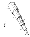
- Figure 1 is a perspective view of a cable of the invention with layers removed to display the internal structure of the cable.
- Figure 2 is a perspective view of a cable of the invention which includes optical signal fibers and electrical signal cables.
- FIG. 1 is a perspective drawing of a cable of the invention which is a single electric signal cable with the various layers removed in order to display the inner structure of the cable.
- the center conductor 1 which may be a solid or a stranded multifilament electrical conductor, is surrounded by insulation 2 or dielectric, which is shown as porous, in that a porous insulation is preferred, especially an ePTFE insulation, described above in the listed patents to that material. Porous polymers show very low dielectric constants, the lowest being that of highly porous ePTFE.
- a thermoplastic insulation may be extruded around center conductor 1 .
- a non-thermoplastic polymer, such as ePTFE is best applied as a spirally wound tape, which may be sintered into a unitary whole after application by application of heat for the required time at a temperature near its initial softening or melting point.
- a thin wrap of metal platable polymer tape 3 is now applied, as little as one overlapping layer of about one micron in thickness being needed.
- Any smooth flexible polymer tape may be used which has mechanical voids, crevaces, and the like to which a metal layer may cling or be wedged into to provide a mechanical grip on the polymer surface.
- Polyamide nylon is the preferred polymer in that numerous effective metal-plating processes are known which can lay down a very thin smooth plating of a conductive or magnetic metal on polyamide.
- the polymer tape may be metal-plated, then wrapped around insulation 2 or the polymer tape may be first wrapped around insulation 2 , heat sealed, then metal-plated.
- the metal layer 4 plated on tape 3 is very thin and may be of an electrically conductive metal or alloy, such as copper, aluminum, silver, or gold or may be a magnetic metal, such as iron, cobalt, nickel or transition metal, which may also be electrically conductive.
- the plating 4 blocks signal interfering radiation from penetrating the cable to the signal conductor 1 or any signal from radiating outwardly from the cable to disturb signals in an adjacent cable or electronic apparatus.
- the cable is usually finished by applying a protective polymer jacket 5 to the outside of the cable, usually by extrusion of a thermoplastic highly resistant to damages from the environment of the cable.
- a protective polymer jacket 5 usually by extrusion of a thermoplastic highly resistant to damages from the environment of the cable.
- Polyvinyl chloride, polyurethane, chloroprene type rubber, and fluorinated olefin polymers are examples of useful jacket polymers.
- a sintered ePTFE tape wrapped jacket may be used.
- each cable having its own insulation, the cables as a unit being covered with a layer of extruded polyamide or a tape-wrap of polyamide tape.
- optical fiber signal cables are included in the cable of the invention, one or more single or multi-mode optical fibers may be included, but at least one electrical signal cable must also be included in the unit.
- a cable is shown in Figure 2, where insulated electrical signal cables 6 are bundled with optical fiber signal cables 7 inside insulation 2 .
- a thin layer of polyamide 3 is extruded or tape-wrapped over insulation 2 .
- Conductive metal layer 4 is then plated on polyamide layer 3 .
- the cable of the invention provides a very lightweight flexible thin cable having good electrical and/or magnetic protection of the signals it transmits.
- the thinness of the overall cable combined with the thinness of the shielding layer results in a cable of unusual flexibility and a minimum amount of material needed to provide a high level of signal capacity and quality.
Landscapes
- Physics & Mathematics (AREA)
- General Physics & Mathematics (AREA)
- Optics & Photonics (AREA)
- Insulated Conductors (AREA)
- Communication Cables (AREA)
- Optical Fibers, Optical Fiber Cores, And Optical Fiber Bundles (AREA)
Abstract
Claims (8)
- Un câble pour signaux comprenant, de l'intérieur vers l'extérieur:(a) au moins un câble pour signaux électriques (1);(b) de façon optionnelle, un ou plusieurs câbles à fibres optiques monomodes ou multimodes;(c) ledit au moins un câble pour signaux électriques comprenant un conducteur central à plusieurs filaments rigides ou en toron, en métal conducteur, entouré par un isolant (2);(d) ledit au moins un câble à fibres optiques comprenant un polymère ou une fibre de verre à quartz recouverte d'un fluoropolymère amorphe ou d'un revêtement de verre d'indice de réfraction inférieur à celui de ladite fibre, et entouré par une couche tampon de polytétrafluoroéthylène mou expansé;(e) une couche de polymère comportant une surface pouvant être recouverte de métal, non lisse (3);(f) une couche mince de métal recouvrant cu enrobant ladite surface de polymère (4); et(g) une enveloppe protectrice de polymère optionnelle (5) .
- Le câble selon la revendication 1, dans lequel ledit isolant électrique comprend un polymère poreux.
- Le câble selon la revendication 2, dans lequel ledit polymère poreux comprend du polytétrafluoroéthylène expansé.
- Le câble selon la revendication 3, dans lequel ledit polymère comportant une surface pouvant être recouverte de métal comprend du polyamide.
- Le câble selon la revendication 4, dans lequel ledit polyamide comprend une bande de polyamide.
- Le câble selon la revendication 5, dans lequel ladite couche de métal est choisie dans le groupe constitué de cuivre, aluminium, argent, or, fer, nickel, cobalt, un métal de transition magnétique et des alliages conducteurs ou magnétiques de ceux-ci.
- Le câble selon la revendication 1, dans lequel ladite couche de polymère (c) a une épaisseur inférieure à 2 µm.
- Le câble selon la revendication 1, dans lequel ladite couche de métal recouvrant ou enrobant ladite surface polymère a une épaisseur inférieure à 1 µm.
Applications Claiming Priority (3)
| Application Number | Priority Date | Filing Date | Title |
|---|---|---|---|
| US07/915,971 US5237635A (en) | 1992-07-15 | 1992-07-15 | Signal cable having metal-plated polymer shielding |
| US915971 | 1992-07-15 | ||
| PCT/US1992/007116 WO1994002949A1 (fr) | 1992-07-15 | 1992-08-21 | Cable pour signaux muni d'un blindage polymere metallise |
Publications (2)
| Publication Number | Publication Date |
|---|---|
| EP0650633A1 EP0650633A1 (fr) | 1995-05-03 |
| EP0650633B1 true EP0650633B1 (fr) | 1996-01-17 |
Family
ID=25436496
Family Applications (1)
| Application Number | Title | Priority Date | Filing Date |
|---|---|---|---|
| EP93903383A Expired - Lifetime EP0650633B1 (fr) | 1992-07-15 | 1992-08-21 | Cable pour signaux muni d'un blindage polymere metallise |
Country Status (7)
| Country | Link |
|---|---|
| US (1) | US5237635A (fr) |
| EP (1) | EP0650633B1 (fr) |
| JP (1) | JPH07509340A (fr) |
| DE (1) | DE69207783T2 (fr) |
| FR (1) | FR2693828A1 (fr) |
| IT (1) | ITTO930526A1 (fr) |
| WO (1) | WO1994002949A1 (fr) |
Families Citing this family (35)
| Publication number | Priority date | Publication date | Assignee | Title |
|---|---|---|---|---|
| DE4302695A1 (de) * | 1993-02-01 | 1994-08-04 | Eilentropp Kg | Elektrische Heizung |
| US5467507A (en) * | 1993-09-17 | 1995-11-21 | Emhart Inc. | Polymer cable check strap |
| US5687271A (en) * | 1994-03-15 | 1997-11-11 | Mario Rabinowitz | Shielded fiber optics cable for compatibility with high voltage power lines |
| US5418878A (en) * | 1994-05-09 | 1995-05-23 | Metropolitan Communication Authority, Inc. | Multi-mode communications cable having a coaxial cable with twisted electrical conductors and optical fibers |
| US5956445A (en) * | 1994-05-20 | 1999-09-21 | Belden Wire & Cable Company | Plenum rated cables and shielding tape |
| US5666452A (en) * | 1994-05-20 | 1997-09-09 | Belden Wire & Cable Company | Shielding tape for plenum rated cables |
| US5468995A (en) * | 1994-07-05 | 1995-11-21 | Motorola, Inc. | Semiconductor device having compliant columnar electrical connections |
| US5519172A (en) * | 1994-09-13 | 1996-05-21 | W. L. Gore & Associates, Inc. | Jacket material for protection of electrical conductors |
| US5793921A (en) * | 1995-03-20 | 1998-08-11 | Psi Telecommunications, Inc. | Kit and method for converting a conductive cable closure to a fiber optic cable closure |
| US5568584A (en) * | 1995-03-20 | 1996-10-22 | Psi Telecommunications, Inc. | Fiber optic closure with cable adapter spool |
| WO1997022025A1 (fr) * | 1995-12-08 | 1997-06-19 | Psi Telecommunications, Inc. | Plateau porte-epissures de fibres optiques |
| US5911145A (en) | 1996-07-29 | 1999-06-08 | Rae Technology, Inc. | Hierarchical structure editor for web sites |
| US6246006B1 (en) | 1998-05-01 | 2001-06-12 | Commscope Properties, Llc | Shielded cable and method of making same |
| US6384337B1 (en) | 2000-06-23 | 2002-05-07 | Commscope Properties, Llc | Shielded coaxial cable and method of making same |
| KR20030033334A (ko) * | 2001-10-18 | 2003-05-01 | 글로벌광통신 (주) | 광섬유 및 전선 통합케이블 |
| US6801695B2 (en) * | 2002-01-04 | 2004-10-05 | Corning Cable Systems Llc | Fiber optic cable having a low-shrink cable jacket and methods of manufacturing the same |
| EP1357406A3 (fr) * | 2002-04-22 | 2003-12-10 | Nortel Networks Limited | Arrangement avec effet de blindage d'un guide d'onde et une boíte |
| JP2004111317A (ja) * | 2002-09-20 | 2004-04-08 | Mitsumi Electric Co Ltd | Emi抑止ケーブル |
| US20040130843A1 (en) * | 2002-12-24 | 2004-07-08 | Takaki Tsutsui | EMI suppressing cable and method of producing EMI suppressing cable |
| CN1694602B (zh) * | 2004-05-09 | 2010-05-05 | 易鼎股份有限公司 | 具有屏蔽平面层的扁平型软性电路板结构 |
| DE502005006823D1 (de) * | 2005-08-31 | 2009-04-23 | Nexans | Verbundkabel |
| US20090123109A1 (en) | 2007-11-09 | 2009-05-14 | Lxdata Inc | Temperature sensor using an optical fiber |
| US8041165B2 (en) * | 2009-04-17 | 2011-10-18 | Baker Hughes Incorporated | System, method and apparatus for power transmission cable with optical fiber for downhole tool in subterranean applications |
| US8204348B2 (en) * | 2009-06-30 | 2012-06-19 | Nexans | Composite, optical fiber, power and signal tactical cable |
| US9046671B2 (en) * | 2010-05-14 | 2015-06-02 | Sumitomo Electric Industries, Ltd. | Composite optical fiber cable and composite optical fiber cable assembly providing protection by flexure |
| CN103854762B (zh) * | 2012-11-29 | 2016-09-14 | 桐庐瑞克斯医疗器械有限公司 | 一种医疗器械用连接线 |
| US9784937B2 (en) | 2013-02-01 | 2017-10-10 | Ccs Technology, Inc. | Cable assembly having electrical power conductors and fiber optic data lines |
| EP2762938B1 (fr) * | 2013-02-01 | 2020-07-15 | Corning Optical Communications LLC | Ensemble de câbles possédant des conducteurs de puissance électrique et lignes de données par fibre optique et une dérivation avec protection |
| WO2016144337A1 (fr) | 2015-03-10 | 2016-09-15 | Halliburton Energy Services Inc. | Procédé de fabrication d'un câble de détection acoustique répartie |
| WO2016144334A1 (fr) | 2015-03-10 | 2016-09-15 | Halliburton Energy Services Inc. | Boîtier de câble à fibre optique sensible aux contraintes pour détection acoustique répartie de fond de trou |
| WO2016144336A1 (fr) | 2015-03-10 | 2016-09-15 | Halliburton Energy Services Inc. | Système de surveillance de puits de forage mettant en œuvre un boîtier de câble à fibre optique sensible aux contraintes |
| CN105070387A (zh) * | 2015-08-07 | 2015-11-18 | 江苏远方电缆厂有限公司 | 一种抗干扰复合电缆 |
| RU178398U1 (ru) * | 2017-06-27 | 2018-04-05 | Акционерное общество "Самарская кабельная компания" | Кабель для сигнализации и блокировки с полиэтиленовой изоляцией, с водоблокирующими материалами, в алюминиевой оболочке, пластмассовой оболочке бронированный |
| JP7256519B2 (ja) * | 2017-12-20 | 2023-04-12 | 株式会社潤工社 | ケーブル |
| WO2019124455A1 (fr) | 2017-12-20 | 2019-06-27 | 株式会社 潤工社 | Câble |
Family Cites Families (14)
| Publication number | Priority date | Publication date | Assignee | Title |
|---|---|---|---|---|
| US3612743A (en) * | 1970-10-13 | 1971-10-12 | Nasa | Shielded flat cable |
| GB1425928A (en) * | 1972-11-10 | 1976-02-25 | Bicc Ltd | Optical guides |
| FR2358735A1 (fr) * | 1976-07-16 | 1978-02-10 | Thomson Csf | Cable coaxial a fibres optiques |
| GB1601002A (en) * | 1977-12-21 | 1981-10-21 | Bicc Ltd | Optical cables |
| DE3020622C2 (de) * | 1980-05-30 | 1985-05-15 | W.L. Gore & Associates, Inc., Newark, Del. | Bandkabel und Verfahren zu seiner Herstellung |
| JPS6086515A (ja) * | 1983-10-18 | 1985-05-16 | Junkosha Co Ltd | 光伝送条体及びこれを用いたフラツトケ−ブル |
| NO155076C (no) * | 1984-03-22 | 1987-02-04 | Standard Tel Kabelfab As | Fiberoptisk kabel. |
| US4852965A (en) * | 1987-02-27 | 1989-08-01 | American Telephone And Telegraph Company At&T Bell Laboratories | Composite service and distribution communications media |
| JPH0292997U (fr) * | 1989-01-12 | 1990-07-24 | ||
| US5037999A (en) * | 1990-03-08 | 1991-08-06 | W. L. Gore & Associates | Conductively-jacketed coaxial cable |
| US5002359A (en) * | 1990-05-22 | 1991-03-26 | W. L. Gore & Associates, Inc. | Buffered insulated optical waveguide fiber cable |
| US5107076A (en) * | 1991-01-08 | 1992-04-21 | W. L. Gore & Associates, Inc. | Easy strip composite dielectric coaxial signal cable |
| US5138684A (en) * | 1991-01-14 | 1992-08-11 | W. L. Gore & Associates, Inc. | High-strength isolated core cable |
| US5189721A (en) * | 1992-02-14 | 1993-02-23 | W. L. Gore & Associates, Inc. | Optical fiber ribbon cable |
-
1992
- 1992-07-15 US US07/915,971 patent/US5237635A/en not_active Expired - Fee Related
- 1992-08-21 EP EP93903383A patent/EP0650633B1/fr not_active Expired - Lifetime
- 1992-08-21 WO PCT/US1992/007116 patent/WO1994002949A1/fr not_active Ceased
- 1992-08-21 JP JP6504396A patent/JPH07509340A/ja active Pending
- 1992-08-21 DE DE69207783T patent/DE69207783T2/de not_active Expired - Fee Related
-
1993
- 1993-07-12 FR FR9308571A patent/FR2693828A1/fr not_active Withdrawn
- 1993-07-14 IT IT93TO000526A patent/ITTO930526A1/it not_active IP Right Cessation
Also Published As
| Publication number | Publication date |
|---|---|
| ITTO930526A1 (it) | 1994-01-17 |
| EP0650633A1 (fr) | 1995-05-03 |
| JPH07509340A (ja) | 1995-10-12 |
| WO1994002949A1 (fr) | 1994-02-03 |
| DE69207783T2 (de) | 1996-06-20 |
| US5237635A (en) | 1993-08-17 |
| FR2693828A1 (fr) | 1994-01-21 |
| DE69207783D1 (de) | 1996-02-29 |
| ITTO930526A0 (it) | 1993-07-14 |
Similar Documents
| Publication | Publication Date | Title |
|---|---|---|
| EP0650633B1 (fr) | Cable pour signaux muni d'un blindage polymere metallise | |
| US5283390A (en) | Twisted pair data bus cable | |
| EP0300334B1 (fr) | Utilisation d' un câble coaxial | |
| US5132491A (en) | Shielded jacketed coaxial cable | |
| US4965412A (en) | Coaxial electrical cable construction | |
| US5061823A (en) | Crush-resistant coaxial transmission line | |
| KR100609199B1 (ko) | 데이터전송케이블 | |
| US4641110A (en) | Shielded radio frequency transmission cable having propagation constant enhancing means | |
| US4822950A (en) | Nickel/carbon fiber braided shield | |
| US8178785B2 (en) | Flexible electric cable | |
| US4868565A (en) | Shielded cable | |
| WO2007146704A1 (fr) | Conducteur composite métal/céramique et câble le comprenant | |
| US20060254801A1 (en) | Shielded electrical transmission cables and methods for forming the same | |
| WO1992001301A1 (fr) | Cable-ruban a propagation a grande vitesse | |
| WO1994022039A1 (fr) | Cable coaxial a fibre optique et assemblage avec un connecteur | |
| EP1122569A1 (fr) | Cable quadruple | |
| EP0784327A1 (fr) | Câble pour ligne de transmission | |
| WO1994016451A1 (fr) | Cables a couches multiples pour la transmission en temps identique de signaux electriques | |
| CN211507180U (zh) | 工业计算机设备及以太网连接电缆 | |
| EP1076343A1 (fr) | Blindage de câble | |
| TW202341188A (zh) | 同軸纜線及其訊號傳輸總成 | |
| CN120565191A (zh) | 一种用于车载通信系统的高性能同轴电缆 | |
| CN111029025A (zh) | 工业计算机设备及以太网连接电缆 | |
| JPH09213142A (ja) | 通信ケーブルおよびその製造方法 | |
| JP2001338536A (ja) | 同軸ケーブル |
Legal Events
| Date | Code | Title | Description |
|---|---|---|---|
| PUAI | Public reference made under article 153(3) epc to a published international application that has entered the european phase |
Free format text: ORIGINAL CODE: 0009012 |
|
| 17P | Request for examination filed |
Effective date: 19950112 |
|
| AK | Designated contracting states |
Kind code of ref document: A1 Designated state(s): DE FR GB IT SE |
|
| 17Q | First examination report despatched |
Effective date: 19950522 |
|
| GRAA | (expected) grant |
Free format text: ORIGINAL CODE: 0009210 |
|
| AK | Designated contracting states |
Kind code of ref document: B1 Designated state(s): DE FR GB IT SE |
|
| ITF | It: translation for a ep patent filed | ||
| REF | Corresponds to: |
Ref document number: 69207783 Country of ref document: DE Date of ref document: 19960229 |
|
| ET | Fr: translation filed | ||
| PLBE | No opposition filed within time limit |
Free format text: ORIGINAL CODE: 0009261 |
|
| STAA | Information on the status of an ep patent application or granted ep patent |
Free format text: STATUS: NO OPPOSITION FILED WITHIN TIME LIMIT |
|
| 26N | No opposition filed | ||
| PGFP | Annual fee paid to national office [announced via postgrant information from national office to epo] |
Ref country code: FR Payment date: 19970721 Year of fee payment: 6 |
|
| PGFP | Annual fee paid to national office [announced via postgrant information from national office to epo] |
Ref country code: DE Payment date: 19970722 Year of fee payment: 6 Ref country code: SE Payment date: 19970722 Year of fee payment: 6 |
|
| PGFP | Annual fee paid to national office [announced via postgrant information from national office to epo] |
Ref country code: GB Payment date: 19970728 Year of fee payment: 6 |
|
| PG25 | Lapsed in a contracting state [announced via postgrant information from national office to epo] |
Ref country code: GB Free format text: LAPSE BECAUSE OF NON-PAYMENT OF DUE FEES Effective date: 19980821 |
|
| PG25 | Lapsed in a contracting state [announced via postgrant information from national office to epo] |
Ref country code: SE Free format text: LAPSE BECAUSE OF NON-PAYMENT OF DUE FEES Effective date: 19980822 |
|
| GBPC | Gb: european patent ceased through non-payment of renewal fee |
Effective date: 19980821 |
|
| PG25 | Lapsed in a contracting state [announced via postgrant information from national office to epo] |
Ref country code: FR Free format text: LAPSE BECAUSE OF NON-PAYMENT OF DUE FEES Effective date: 19990430 |
|
| EUG | Se: european patent has lapsed |
Ref document number: 93903383.3 |
|
| PG25 | Lapsed in a contracting state [announced via postgrant information from national office to epo] |
Ref country code: DE Free format text: LAPSE BECAUSE OF NON-PAYMENT OF DUE FEES Effective date: 19990601 |
|
| REG | Reference to a national code |
Ref country code: FR Ref legal event code: ST |
|
| PG25 | Lapsed in a contracting state [announced via postgrant information from national office to epo] |
Ref country code: IT Free format text: LAPSE BECAUSE OF NON-PAYMENT OF DUE FEES;WARNING: LAPSES OF ITALIAN PATENTS WITH EFFECTIVE DATE BEFORE 2007 MAY HAVE OCCURRED AT ANY TIME BEFORE 2007. THE CORRECT EFFECTIVE DATE MAY BE DIFFERENT FROM THE ONE RECORDED. Effective date: 20050821 |