EP0650656B1 - Haut-parleur - Google Patents
Haut-parleur Download PDFInfo
- Publication number
- EP0650656B1 EP0650656B1 EP93916102A EP93916102A EP0650656B1 EP 0650656 B1 EP0650656 B1 EP 0650656B1 EP 93916102 A EP93916102 A EP 93916102A EP 93916102 A EP93916102 A EP 93916102A EP 0650656 B1 EP0650656 B1 EP 0650656B1
- Authority
- EP
- European Patent Office
- Prior art keywords
- dome
- loudspeaker
- gasket
- former
- pole
- Prior art date
- Legal status (The legal status is an assumption and is not a legal conclusion. Google has not performed a legal analysis and makes no representation as to the accuracy of the status listed.)
- Expired - Lifetime
Links
Images
Classifications
-
- H—ELECTRICITY
- H04—ELECTRIC COMMUNICATION TECHNIQUE
- H04R—LOUDSPEAKERS, MICROPHONES, GRAMOPHONE PICK-UPS OR LIKE ACOUSTIC ELECTROMECHANICAL TRANSDUCERS; ELECTRIC HEARING AIDS; PUBLIC ADDRESS SYSTEMS
- H04R1/00—Details of transducers, loudspeakers or microphones
- H04R1/20—Arrangements for obtaining desired frequency or directional characteristics
- H04R1/22—Arrangements for obtaining desired frequency or directional characteristics for obtaining desired frequency characteristic only
- H04R1/24—Structural combinations of separate transducers or of two parts of the same transducer and responsive respectively to two or more frequency ranges
-
- H—ELECTRICITY
- H04—ELECTRIC COMMUNICATION TECHNIQUE
- H04R—LOUDSPEAKERS, MICROPHONES, GRAMOPHONE PICK-UPS OR LIKE ACOUSTIC ELECTROMECHANICAL TRANSDUCERS; ELECTRIC HEARING AIDS; PUBLIC ADDRESS SYSTEMS
- H04R2207/00—Details of diaphragms or cones for electromechanical transducers or their suspension covered by H04R7/00 but not provided for in H04R7/00 or in H04R2307/00
- H04R2207/021—Diaphragm extensions, not necessarily integrally formed, e.g. skirts, rims, flanges
-
- H—ELECTRICITY
- H04—ELECTRIC COMMUNICATION TECHNIQUE
- H04R—LOUDSPEAKERS, MICROPHONES, GRAMOPHONE PICK-UPS OR LIKE ACOUSTIC ELECTROMECHANICAL TRANSDUCERS; ELECTRIC HEARING AIDS; PUBLIC ADDRESS SYSTEMS
- H04R2209/00—Details of transducers of the moving-coil, moving-strip, or moving-wire type covered by H04R9/00 but not provided for in any of its subgroups
- H04R2209/043—Short circuited voice coils driven by induction
-
- H—ELECTRICITY
- H04—ELECTRIC COMMUNICATION TECHNIQUE
- H04R—LOUDSPEAKERS, MICROPHONES, GRAMOPHONE PICK-UPS OR LIKE ACOUSTIC ELECTROMECHANICAL TRANSDUCERS; ELECTRIC HEARING AIDS; PUBLIC ADDRESS SYSTEMS
- H04R2499/00—Aspects covered by H04R or H04S not otherwise provided for in their subgroups
- H04R2499/10—General applications
- H04R2499/13—Acoustic transducers and sound field adaptation in vehicles
-
- H—ELECTRICITY
- H04—ELECTRIC COMMUNICATION TECHNIQUE
- H04R—LOUDSPEAKERS, MICROPHONES, GRAMOPHONE PICK-UPS OR LIKE ACOUSTIC ELECTROMECHANICAL TRANSDUCERS; ELECTRIC HEARING AIDS; PUBLIC ADDRESS SYSTEMS
- H04R9/00—Transducers of moving-coil, moving-strip, or moving-wire type
- H04R9/06—Loudspeakers
- H04R9/063—Loudspeakers using a plurality of acoustic drivers
Definitions
- This invention relates to a loudspeaker incorporating an inductively coupled tweeter particularly, but not necessarily only, for use in an automotive audio system and starts from EP-A-0'344'975.
- a loudspeaker conventionally comprises a magnet assembly with an annular gap having a radial magnetic field within the gap.
- a voice coil is suspended in the magnetic field by means which permit it to be moved axially without touching the sides of the magnet assembly.
- the voice coil is wound on a rigid tube that is connected to a diaphragm, the outer edge of which is flexibly supported by a frame that is itself securely attached to a part of the magnet assembly.
- the frequency range of the sound produced is limited to low and medium frequency and, in order to reproduce high frequency sounds, it is proposed to incorporate an inductively coupled tweeter.
- GB 545712 discloses an inductively coupled conductor in the form of a radiating dome positioned in the magnetic gap inside the main voice coil of a loudspeaker.
- the low and medium frequency sounds are radiated by a conventional cone, the high frequency sound is produced by the dome and is directionally controlled by a special horn fixed to the centre pole.
- a radiating dome is positioned over the central pole and supported by an annular suspension means.
- the dome is positioned within the tube or former supporting the voice coil and receives its energizing signals inductively from the voice coil.
- the dome is horn loaded by the same diaphragm as the voice coil, but reproduces high frequency sound.
- European Publication 0344974 is an improvement on the loudspeaker disclosed in GB Patent No.2118398 and includes a fixed element providing phase correction, which is supported by the pole through a hole in the dome.
- the radiating dome is supported by an annular flexible suspension on the pole face and also by another smaller flexible suspension on the underside of the phase correcting device. This provides two small sealed chambers.
- European Publication No. 0344975 discloses a similar electro acoustic transducer as disclosed in GB Patent No. 2188398 but is directed to the provision of an electrically insulating layer between the dome and the centre pole. This allows the annular gap to be of a minimum clearance whilst eliminating short circuiting between the pole and the dome.
- An object of the present invention is to provide an improved loudspeaker with an inductively coupled tweeter.
- a loudspeaker comprising a pole, a surrounding magnet defining an annular gap with the pole, a tubular former, a voice coil carried by the former and disposed within the annular gap, and a conductive skirted dome supported on the pole upon an insulated support with the skirt disposed in the annular gap so as to be inductively coupled with the voice coil when the voice coil is energized, characterized in that the insulated support provides a plurality of spaced positions of support.
- the done is supported upon three arcuate points of support.
- the three points of support may be provided by a gasket shaped to provide the arcuate points of support.
- the conductive dome suitably includes a central opening with a clearance to receive a phase plug attached to the pole by a stem passing through the opening.
- the underside of the phase plug may include a second gasket around its central supporting peg, to which the dome may or may not be bonded, to limit travel of the dome and to ensure that the skirt is always located in the annular magnetic gap.
- the phase plug may include a horn extending beyond the former.
- the dome for forming the inductively coupled tweeter in the loudspaker may comprise an electrically conductive skirt and an insulated domed portion to generate high frequency sound.
- the insulated domed portion may be selected from a non-electrically conductive material such as paper or plastics material or an electrically conductive material such as aluminium but insulated from the skirt.
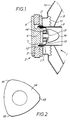
- a loudspeaker 1 comprises a conventional back assembly 2 consisting of a magnet ring 3 having a yoke 4 and an annular front plate 5 bonded to the magnet ring 3.
- the yoke 4 includes a cylindrical pole 6 extending through the openings defined by the annular plate 5 and the magnet ring 3 to define an annular gap 7.
- a hollow cylindrical former 8 is arranged to extend concentrically over a free end of the centre pole 6 and to lie partly within the annular gap 7 and a diaphragm 9 is bonded to the former.
- the former 8 and the diaphragm 9 are mounted to a fixed chassis 10 by means of a flexible suspension 11.
- a voice coil 12 is wound over the former and lies within the annular gap 7.
- an inductively coupled tweeter which consists of an aluminum dome 13 supported within the gap 7 upon a gasket 14 providing three arcuate spaced positions of support.
- the dome 13 is inductively coupled to the voice coil 12 and includes a central aperture 15 through which a fixed phase plug 16 is mounted within the former 8.
- the dome 13 is a one piece aluminium foil dome with a skirt 17 that is located in the annular magnetic gap 7 inside the main voice coil 12.
- the dome 13 is free to vibrate but is supported on the gasket 14 which is a compliant gasket bonded to the end face of pole 6.
- the gasket is of such a shape that it will make contact at approximately three equally spaced arcuate positions 18.
- the gasket suspension allows the dome 13 to float free with the minimum of support from the gasket 14.
- the positions of support 18 defined by the outermost part of the gasket 14 are disposed radially inwardly of the edge of the pole 6. This arrangement supports the dome 13 just above the radius on the pole edge so that the dome 13 does not buzz or touch the pole in operation.
- the dome 13 may be supported at more or less spaced positions and the positions need not be equally spaced.
- the dome may or may not be actually bonded to the gasket by self adhesive or other means.
- the gasket may be bonded or located concentrically on the face of the pole 6.
- a second soft gasket (not shown in Figure 1) may be provided around the underside of the phase plug 16 to gently retain the dome 13 in the correct position touching either in a circle of contact or in several places only.
- the second gasket may or may not be bonded to the dome 13. If the second gasket is bonded to the dome 13 as well as to the underside of the phase plug 16 the gasket secures the dome 13 so that it is not free-floating but the material of the dome 13 allows it to flex in use.
- the phase plug 16 suitably has an underside radius that is very similar to the dome 13 in order that it can fit closely although there may be a recess in the underside to locate the second soft gasket in position if provided. If desired the inside of the dome 13 or the outside of the pole 6 may be insulated in accordance with normal established electrical practice with conductors adjacent to other metal parts to prevent the dome 13 shorting on the pole 6.
- the former 8 may be provided with a conventional paper whizzer (not shown) for acoustical matching purposes to radiate the higher frequencies produced by the tweeter and voice coil.
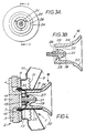
- the phase plug may include a separate or integral horn as shown in Figures 3a and 3b.
- the phase plug 16 includes a central phase correction portion 19 and a horn portion 20.
- the central portion 19 may have a centre hole 21 to allow fixture to the pole 6.
- the horn portion 20 is spaced from the central portion 19 to define a sound throat 22 and is fixed in position by three or more thin webs 23 connecting the horn portion 20 to the central portion 19.
- the horn portion 20 is flared outwardly and, on its outer surface, includes an annular shoulder 24 dimensioned to provide an annular rebate 25 which receives the moving free end of the former 8.
- the inner end surface 26 of the horn portion 20 is curved as shown to conform substantially with the curved surface of the dome 13.
- the arrangement is shown in section in Figure 4 with a second gasket 27 bonded to both the dare and underside of the phase plug.
- low and medium frequency sound is radiated by the diaphragm 9 and high frequency sound generated by the inductively coupled dome 13 is amplified and directionally controlled by the sound throat 22 of the horn portion 20.
- the outer surface of the horn portion 20 co-operates with the free end of the former 8 and the shoulder 24 will be aligned with the free end of the former 8 there is no sound passage between the outer surface of the horn portion 20 and the former 8 so that the high frequency sound produced by the dome 13 is all directionally radiated by the flared surface of the horn portion 20.
- the horn portion 20 is not attached in any way to the former 8 and, being preferably integral with the phase correction portion 19, provides stable acoustical matching and reduced mass compared with a horn attached to the moving former 8.
- central portion 19 and horn portion 20 are shown as integrally moulded they may be separate if desired.
- the reduced line of support by using a 3-point suspension gasket on the pole face reduces the suspended mass and allows the dome to reproduce with a smoother frequency response and with improved sensitivity.
- the dome 13 is described as a one piece aluminium foil dome.
- the skirt 17 may be conductive with a non-conductive paper or plastic curved top surface.
Landscapes
- Health & Medical Sciences (AREA)
- Otolaryngology (AREA)
- Physics & Mathematics (AREA)
- Engineering & Computer Science (AREA)
- Acoustics & Sound (AREA)
- Signal Processing (AREA)
- Audible-Bandwidth Dynamoelectric Transducers Other Than Pickups (AREA)
- Diaphragms For Electromechanical Transducers (AREA)
- Liquid Crystal (AREA)
- Surgical Instruments (AREA)
- Chair Legs, Seat Parts, And Backrests (AREA)
Claims (12)
- Haut-parleur (1) comprenant un pôle (6), un aimant qui l'entoure (3), délimitant un espace annulaire (7) par rapport au pôle, un gabarit tubulaire (8), une bobine mobile de haut-parleur (12) supportée par le gabarit (8) et montée à l'intérieur de l'espace annulaire (7), et un dôme conducteur chemisé (13) supporté sur le pôle par l'intermédiaire d'un support isolé (14), la chemise étant placée dans l'espace annulaire (7) pour être couplée inductivement avec la bobine mobile (12) lorsque la bobine mobile est excitée, caractérisé en ce que le support isolé (14) comporte une pluralité de positions espacées du support (18).
- Haut-parleur (1) selon la revendication 1, dans lequel le dôme (13) est supporté sur trois positions espacées du support (18).
- Haut-parleur (1) selon la revendication 2, dans lequel les trois position du support (18) sont cintrées et pourvues d'un joint mis en forme (14).
- Haut-parleur (1) selon la revendication 3, dans laquelle le joint (14) est fixé à l'intérieur du dôme (13).
- Haut-parleur (1) selon l'une quelconque des revendications précédentes, dans lequel le dôme (13) est une pièce fabriquée en feuille d'aluminium.
- Haut-parleur (1) selon l'une quelconque des revendications précédentes, dans lequel le dôme (13) comporte une ouverture centrale (15) avec un certain jeu pour recevoir une fiche de phase (16) reliée au pôle (6), par une tige traversant l'ouverture.
- Haut-parleur (1) selon la revendication 5, comprenant un second joint (27) placé entre le dessous de la fiche de phase (16) et le dessus du dôme (13).
- Haut-parleur (1) selon la revendication 7, dans lequel le second joint (27) est fixé à la fois sur la fiche de phase (16) et sur le dôme (13) pour maintenir le dôme en place.
- Haut-parleur (1) selon l'une des revendications 6, 7 ou 8, dans lequel la fiche de phase (16) comprend un cornet (20) s'étendant au-delà du gabarit (8) et comprenant une feuillure (25) pour admettre le mouvement du gabarit.
- Haut-parleur (1) selon la revendication 9, dans lequel le cornet (20) est intégré à la fiche de phase (16).
- Haut-parleur (1) selon l'une quelconque des revendications précédentes, dans lequel le dôme (13) comprend une chemise électriquement conductrice et une partie isolée en dôme pour générer un son à haute fréquence.
- Haut-parleur (1) selon la revendication 11, dans lequel la partie isolée du dôme est choisie parmi : un matériau non conducteur de l'électricité tel que du papier de matière plastique ou un matériau électriquement conducteur tel que de l'aluminium mais isolé de la chemise.
Applications Claiming Priority (3)
| Application Number | Priority Date | Filing Date | Title |
|---|---|---|---|
| GB929215222A GB9215222D0 (en) | 1992-07-17 | 1992-07-17 | Loudspeaker |
| GB9215222 | 1992-07-17 | ||
| PCT/GB1993/001509 WO1994003024A1 (fr) | 1992-07-17 | 1993-07-16 | Haut-parleur |
Publications (2)
| Publication Number | Publication Date |
|---|---|
| EP0650656A1 EP0650656A1 (fr) | 1995-05-03 |
| EP0650656B1 true EP0650656B1 (fr) | 1996-05-22 |
Family
ID=10718877
Family Applications (1)
| Application Number | Title | Priority Date | Filing Date |
|---|---|---|---|
| EP93916102A Expired - Lifetime EP0650656B1 (fr) | 1992-07-17 | 1993-07-16 | Haut-parleur |
Country Status (8)
| Country | Link |
|---|---|
| US (1) | US5602930A (fr) |
| EP (1) | EP0650656B1 (fr) |
| AT (1) | ATE138524T1 (fr) |
| CA (1) | CA2137075C (fr) |
| DE (1) | DE69302820T2 (fr) |
| ES (1) | ES2087758T3 (fr) |
| GB (2) | GB9215222D0 (fr) |
| WO (1) | WO1994003024A1 (fr) |
Families Citing this family (21)
| Publication number | Priority date | Publication date | Assignee | Title |
|---|---|---|---|---|
| GB9407101D0 (en) * | 1994-04-09 | 1994-06-01 | Harman Motive Ltd | A modular tweeter |
| US5739480A (en) * | 1996-09-24 | 1998-04-14 | Lin; Steff | Speaker base for alternatively mounting different drivers |
| US6243472B1 (en) * | 1997-09-17 | 2001-06-05 | Frank Albert Bilan | Fully integrated amplified loudspeaker |
| CN1162042C (zh) * | 1999-02-17 | 2004-08-11 | 维弗扬声器公司 | 一种扬声器 |
| FR2794604B1 (fr) * | 1999-06-04 | 2002-12-06 | Pierre Piccaluga | Transformateur electro acoustique pour la reproduction du son |
| US7936892B2 (en) | 2002-01-14 | 2011-05-03 | Harman International Industries, Incorporated | Constant coverage waveguide |
| GB0202284D0 (en) * | 2002-01-31 | 2002-03-20 | Martin Audio Ltd | Directional loudspeaker |
| US20040066947A1 (en) * | 2002-10-04 | 2004-04-08 | Geddes Earl Rossell | Transducer with multiple phase plugs |
| US6731773B1 (en) | 2002-11-01 | 2004-05-04 | Stillwater Designs And Audio, Inc. | Dual basket speaker with replaceable, self-aligning cone assembly and super ventilated pole piece |
| US20050175208A1 (en) * | 2004-02-11 | 2005-08-11 | Shaw Clayton C. | Audio speaker system employing an annular gasket separating a horn waveguide from a sound reproducing membrane |
| US7203329B2 (en) * | 2004-02-11 | 2007-04-10 | Soundtube Entertainment, Inc. | Audio speaker system employing an axi-symmetrical horn with wide dispersion angle characteristics over an extended frequency range |
| RU2262812C1 (ru) * | 2004-05-13 | 2005-10-20 | Общество с ограниченной ответственностью "ПКТЗ" | Коаксиальная акустическая система |
| US7777600B2 (en) * | 2004-05-20 | 2010-08-17 | Powerpath Technologies Llc | Eddy current inductive drive electromechanical liner actuator and switching arrangement |
| US7319772B2 (en) * | 2005-01-07 | 2008-01-15 | George Chang | Speaker device for improving mid/high-range frequencies |
| US7949146B2 (en) * | 2006-06-27 | 2011-05-24 | Mckenzie Mark D | Boundary layer regulator for extended range acoustical transducers |
| MX2009000055A (es) * | 2006-07-12 | 2009-01-23 | Anders Sagren | Conjunto de diafragma de alta frecuencia y bobina de voz. |
| FR2955446B1 (fr) | 2010-01-15 | 2015-06-05 | Phl Audio | Transducteur electrodynamique a dome et suspension flottante |
| FR2955445B1 (fr) | 2010-01-15 | 2013-06-07 | Phl Audio | Transducteur electrodynamique a dome et suspension interne |
| FR2955444B1 (fr) | 2010-01-15 | 2012-08-03 | Phl Audio | Systeme de haut-parleur coaxial a chambre de compression |
| CN104378720B (zh) * | 2013-08-14 | 2018-05-18 | 颜至远 | 扬声器 |
| EP4017025A4 (fr) * | 2019-08-17 | 2023-05-24 | Sound Fun Corporation | Unité de haut-parleur et diaphragme de haut-parleur incurvé |
Family Cites Families (5)
| Publication number | Priority date | Publication date | Assignee | Title |
|---|---|---|---|---|
| GB545712A (en) * | 1941-01-02 | 1942-06-09 | Albert Charles Woods | Improvements in and relating to loud speakers |
| DE3049222A1 (de) * | 1980-12-27 | 1982-07-29 | Elektrotechnik Ehmann Gmbh, 6953 Gundelsheim | Elektrodynamisches lautsprechersystem mit kalottenfoermiger membran |
| GB2118398B (en) * | 1982-04-14 | 1986-04-03 | Boaz Elieli | Moving coil electroacoustic transducers |
| NL8202529A (nl) * | 1982-06-23 | 1984-01-16 | Philips Nv | Elektro-akoestische omzetter met een lange slag. |
| ES2072903T5 (es) * | 1988-06-02 | 2002-05-16 | Boaz Elieli | Transductor electroacustico y altavoz. |
-
1992
- 1992-07-17 GB GB929215222A patent/GB9215222D0/en active Pending
-
1993
- 1993-07-16 AT AT93916102T patent/ATE138524T1/de not_active IP Right Cessation
- 1993-07-16 WO PCT/GB1993/001509 patent/WO1994003024A1/fr not_active Ceased
- 1993-07-16 CA CA002137075A patent/CA2137075C/fr not_active Expired - Fee Related
- 1993-07-16 GB GB9423700A patent/GB2282024B/en not_active Expired - Fee Related
- 1993-07-16 EP EP93916102A patent/EP0650656B1/fr not_active Expired - Lifetime
- 1993-07-16 DE DE69302820T patent/DE69302820T2/de not_active Expired - Lifetime
- 1993-07-16 US US08/367,199 patent/US5602930A/en not_active Expired - Lifetime
- 1993-07-16 ES ES93916102T patent/ES2087758T3/es not_active Expired - Lifetime
Also Published As
| Publication number | Publication date |
|---|---|
| DE69302820D1 (de) | 1996-06-27 |
| ES2087758T3 (es) | 1996-07-16 |
| GB9215222D0 (en) | 1992-09-02 |
| WO1994003024A1 (fr) | 1994-02-03 |
| ATE138524T1 (de) | 1996-06-15 |
| EP0650656A1 (fr) | 1995-05-03 |
| US5602930A (en) | 1997-02-11 |
| GB2282024A (en) | 1995-03-22 |
| GB2282024B (en) | 1995-12-20 |
| DE69302820T2 (de) | 1996-09-26 |
| CA2137075A1 (fr) | 1994-02-03 |
| CA2137075C (fr) | 1998-04-28 |
| GB9423700D0 (en) | 1995-01-11 |
Similar Documents
| Publication | Publication Date | Title |
|---|---|---|
| EP0650656B1 (fr) | Haut-parleur | |
| JP2543765B2 (ja) | 電気音響変換器およびスピ―カ | |
| US5742696A (en) | Modular tweeter | |
| US4550430A (en) | Sound reproducing system utilizing motional feedback and an improved integrated magnetic structure | |
| US20060029247A1 (en) | [suspension member for speaker] | |
| KR0171567B1 (ko) | 라우드스피커 구동유니트 | |
| EP1410682B1 (fr) | Haut-parleur et systeme a faible encombrement | |
| WO2010135106A1 (fr) | Suspension interne de haut-parleur | |
| US8731231B2 (en) | Dynamic sound transducer and receiver | |
| KR102447285B1 (ko) | 이어폰용 스피커 유닛 | |
| EP1755358B1 (fr) | Actionneur oscillant de type multifonction et dispositif terminal mobile | |
| NL2025207B1 (en) | Electroacoustic transducer and loudspeaker, microphone and electronic device comprising said electroacoustic transducer | |
| EP1185139B1 (fr) | Diaphragm pour haut-parleur | |
| US6568502B2 (en) | Sounder, speaker and sound head using the sounder | |
| NZ203080A (en) | Moving coil electroacoustic transducer:two part diaphragm supports coil | |
| GB2360899A (en) | Coaxial loudspeaker with the magnetic circuit mounted in front of the diaphragm | |
| US8208677B2 (en) | Suspension member for speaker | |
| US5526441A (en) | Full range convex electrodynamic loudspeaker | |
| JP3128022B2 (ja) | 同軸スピーカ | |
| JP3787999B2 (ja) | スピーカ | |
| JP4662522B2 (ja) | 電磁形電気音響変換器および携帯端末装置 | |
| KR950008543B1 (ko) | 구동코일 직접 방사식 스피커 | |
| GB2147768A (en) | Electro-acoustic transducer | |
| JPH0733517Y2 (ja) | 電気音響変換器 | |
| JPH07112317B2 (ja) | 電磁誘導型スピーカ |
Legal Events
| Date | Code | Title | Description |
|---|---|---|---|
| PUAI | Public reference made under article 153(3) epc to a published international application that has entered the european phase |
Free format text: ORIGINAL CODE: 0009012 |
|
| 17P | Request for examination filed |
Effective date: 19941220 |
|
| AK | Designated contracting states |
Kind code of ref document: A1 Designated state(s): AT BE CH DE DK ES FR IE IT LI NL PT SE |
|
| 17Q | First examination report despatched |
Effective date: 19950718 |
|
| RBV | Designated contracting states (corrected) |
Designated state(s): AT BE CH DE DK ES FR IE IT LI NL PT SE |
|
| RAP1 | Party data changed (applicant data changed or rights of an application transferred) |
Owner name: HARMAN INTERNATIONAL INDUSTRIES LIMITED |
|
| GRAH | Despatch of communication of intention to grant a patent |
Free format text: ORIGINAL CODE: EPIDOS IGRA |
|
| GRAA | (expected) grant |
Free format text: ORIGINAL CODE: 0009210 |
|
| AK | Designated contracting states |
Kind code of ref document: B1 Designated state(s): AT BE CH DE DK ES FR IE IT LI NL PT SE |
|
| PG25 | Lapsed in a contracting state [announced via postgrant information from national office to epo] |
Ref country code: NL Free format text: LAPSE BECAUSE OF FAILURE TO SUBMIT A TRANSLATION OF THE DESCRIPTION OR TO PAY THE FEE WITHIN THE PRESCRIBED TIME-LIMIT Effective date: 19960522 Ref country code: LI Free format text: LAPSE BECAUSE OF FAILURE TO SUBMIT A TRANSLATION OF THE DESCRIPTION OR TO PAY THE FEE WITHIN THE PRESCRIBED TIME-LIMIT Effective date: 19960522 Ref country code: IT Free format text: LAPSE BECAUSE OF FAILURE TO SUBMIT A TRANSLATION OF THE DESCRIPTION OR TO PAY THE FEE WITHIN THE PRE;WARNING: LAPSES OF ITALIAN PATENTS WITH EFFECTIVE DATE BEFORE 2007 MAY HAVE OCCURRED AT ANY TIME BEFORE 2007. THE CORRECT EFFECTIVE DATE MAY BE DIFFERENT FROM THE ONE RECORDED.SCRIBED TIME-LIMIT Effective date: 19960522 Ref country code: DK Effective date: 19960522 Ref country code: CH Free format text: LAPSE BECAUSE OF FAILURE TO SUBMIT A TRANSLATION OF THE DESCRIPTION OR TO PAY THE FEE WITHIN THE PRESCRIBED TIME-LIMIT Effective date: 19960522 Ref country code: BE Effective date: 19960522 |
|
| REF | Corresponds to: |
Ref document number: 138524 Country of ref document: AT Date of ref document: 19960615 Kind code of ref document: T |
|
| REG | Reference to a national code |
Ref country code: IE Ref legal event code: FG4D Free format text: 68500 Ref country code: ES Ref legal event code: BA2A Ref document number: 2087758 Country of ref document: ES Kind code of ref document: T3 |
|
| REF | Corresponds to: |
Ref document number: 69302820 Country of ref document: DE Date of ref document: 19960627 |
|
| ET | Fr: translation filed | ||
| REG | Reference to a national code |
Ref country code: ES Ref legal event code: FG2A Ref document number: 2087758 Country of ref document: ES Kind code of ref document: T3 |
|
| PG25 | Lapsed in a contracting state [announced via postgrant information from national office to epo] |
Ref country code: IE Free format text: LAPSE BECAUSE OF NON-PAYMENT OF DUE FEES Effective date: 19960722 |
|
| PG25 | Lapsed in a contracting state [announced via postgrant information from national office to epo] |
Ref country code: PT Effective date: 19960822 |
|
| NLV1 | Nl: lapsed or annulled due to failure to fulfill the requirements of art. 29p and 29m of the patents act | ||
| REG | Reference to a national code |
Ref country code: CH Ref legal event code: PL |
|
| PLBE | No opposition filed within time limit |
Free format text: ORIGINAL CODE: 0009261 |
|
| STAA | Information on the status of an ep patent application or granted ep patent |
Free format text: STATUS: NO OPPOSITION FILED WITHIN TIME LIMIT |
|
| 26N | No opposition filed | ||
| PGFP | Annual fee paid to national office [announced via postgrant information from national office to epo] |
Ref country code: ES Payment date: 20100706 Year of fee payment: 18 |
|
| PGFP | Annual fee paid to national office [announced via postgrant information from national office to epo] |
Ref country code: SE Payment date: 20100719 Year of fee payment: 18 Ref country code: FR Payment date: 20100823 Year of fee payment: 18 Ref country code: DE Payment date: 20100723 Year of fee payment: 18 Ref country code: AT Payment date: 20100714 Year of fee payment: 18 |
|
| REG | Reference to a national code |
Ref country code: SE Ref legal event code: EUG |
|
| REG | Reference to a national code |
Ref country code: AT Ref legal event code: MM01 Ref document number: 138524 Country of ref document: AT Kind code of ref document: T Effective date: 20110716 |
|
| REG | Reference to a national code |
Ref country code: FR Ref legal event code: ST Effective date: 20120330 |
|
| PG25 | Lapsed in a contracting state [announced via postgrant information from national office to epo] |
Ref country code: FR Free format text: LAPSE BECAUSE OF NON-PAYMENT OF DUE FEES Effective date: 20110801 Ref country code: DE Free format text: LAPSE BECAUSE OF NON-PAYMENT OF DUE FEES Effective date: 20120201 |
|
| REG | Reference to a national code |
Ref country code: DE Ref legal event code: R119 Ref document number: 69302820 Country of ref document: DE Effective date: 20120201 |
|
| REG | Reference to a national code |
Ref country code: ES Ref legal event code: FD2A Effective date: 20121122 |
|
| PG25 | Lapsed in a contracting state [announced via postgrant information from national office to epo] |
Ref country code: AT Free format text: LAPSE BECAUSE OF NON-PAYMENT OF DUE FEES Effective date: 20110716 |
|
| PG25 | Lapsed in a contracting state [announced via postgrant information from national office to epo] |
Ref country code: ES Free format text: LAPSE BECAUSE OF NON-PAYMENT OF DUE FEES Effective date: 20110717 |
|
| PG25 | Lapsed in a contracting state [announced via postgrant information from national office to epo] |
Ref country code: SE Free format text: LAPSE BECAUSE OF NON-PAYMENT OF DUE FEES Effective date: 20110717 |