EP0650770A2 - Appareil de distribution de produit fluide chauffé - Google Patents
Appareil de distribution de produit fluide chauffé Download PDFInfo
- Publication number
- EP0650770A2 EP0650770A2 EP94115641A EP94115641A EP0650770A2 EP 0650770 A2 EP0650770 A2 EP 0650770A2 EP 94115641 A EP94115641 A EP 94115641A EP 94115641 A EP94115641 A EP 94115641A EP 0650770 A2 EP0650770 A2 EP 0650770A2
- Authority
- EP
- European Patent Office
- Prior art keywords
- plunger
- coil
- fluid
- heat
- electromagnetic field
- Prior art date
- Legal status (The legal status is an assumption and is not a legal conclusion. Google has not performed a legal analysis and makes no representation as to the accuracy of the status listed.)
- Ceased
Links
Images



Classifications
-
- B—PERFORMING OPERATIONS; TRANSPORTING
- B67—OPENING, CLOSING OR CLEANING BOTTLES, JARS OR SIMILAR CONTAINERS; LIQUID HANDLING
- B67D—DISPENSING, DELIVERING OR TRANSFERRING LIQUIDS, NOT OTHERWISE PROVIDED FOR
- B67D99/00—Subject matter not provided for in other groups of this subclass
-
- B—PERFORMING OPERATIONS; TRANSPORTING
- B67—OPENING, CLOSING OR CLEANING BOTTLES, JARS OR SIMILAR CONTAINERS; LIQUID HANDLING
- B67D—DISPENSING, DELIVERING OR TRANSFERRING LIQUIDS, NOT OTHERWISE PROVIDED FOR
- B67D7/00—Apparatus or devices for transferring liquids from bulk storage containers or reservoirs into vehicles or into portable containers, e.g. for retail sale purposes
- B67D7/06—Details or accessories
- B67D7/80—Arrangements of heating or cooling devices for liquids to be transferred
-
- B—PERFORMING OPERATIONS; TRANSPORTING
- B05—SPRAYING OR ATOMISING IN GENERAL; APPLYING FLUENT MATERIALS TO SURFACES, IN GENERAL
- B05C—APPARATUS FOR APPLYING FLUENT MATERIALS TO SURFACES, IN GENERAL
- B05C5/00—Apparatus in which liquid or other fluent material is projected, poured or allowed to flow on to the surface of the work
- B05C5/001—Apparatus in which liquid or other fluent material is projected, poured or allowed to flow on to the surface of the work incorporating means for heating or cooling the liquid or other fluent material
-
- B—PERFORMING OPERATIONS; TRANSPORTING
- B05—SPRAYING OR ATOMISING IN GENERAL; APPLYING FLUENT MATERIALS TO SURFACES, IN GENERAL
- B05C—APPARATUS FOR APPLYING FLUENT MATERIALS TO SURFACES, IN GENERAL
- B05C5/00—Apparatus in which liquid or other fluent material is projected, poured or allowed to flow on to the surface of the work
- B05C5/02—Apparatus in which liquid or other fluent material is projected, poured or allowed to flow on to the surface of the work the liquid or other fluent material being discharged through an outlet orifice by pressure, e.g. from an outlet device in contact or almost in contact, with the work
-
- B—PERFORMING OPERATIONS; TRANSPORTING
- B05—SPRAYING OR ATOMISING IN GENERAL; APPLYING FLUENT MATERIALS TO SURFACES, IN GENERAL
- B05C—APPARATUS FOR APPLYING FLUENT MATERIALS TO SURFACES, IN GENERAL
- B05C5/00—Apparatus in which liquid or other fluent material is projected, poured or allowed to flow on to the surface of the work
- B05C5/02—Apparatus in which liquid or other fluent material is projected, poured or allowed to flow on to the surface of the work the liquid or other fluent material being discharged through an outlet orifice by pressure, e.g. from an outlet device in contact or almost in contact, with the work
- B05C5/0225—Apparatus in which liquid or other fluent material is projected, poured or allowed to flow on to the surface of the work the liquid or other fluent material being discharged through an outlet orifice by pressure, e.g. from an outlet device in contact or almost in contact, with the work characterised by flow controlling means, e.g. valves, located proximate the outlet
-
- B—PERFORMING OPERATIONS; TRANSPORTING
- B05—SPRAYING OR ATOMISING IN GENERAL; APPLYING FLUENT MATERIALS TO SURFACES, IN GENERAL
- B05B—SPRAYING APPARATUS; ATOMISING APPARATUS; NOZZLES
- B05B1/00—Nozzles, spray heads or other outlets, with or without auxiliary devices such as valves, heating means
- B05B1/30—Nozzles, spray heads or other outlets, with or without auxiliary devices such as valves, heating means designed to control volume of flow, e.g. with adjustable passages
- B05B1/3033—Nozzles, spray heads or other outlets, with or without auxiliary devices such as valves, heating means designed to control volume of flow, e.g. with adjustable passages the control being effected by relative coaxial longitudinal movement of the controlling element and the spray head
- B05B1/304—Nozzles, spray heads or other outlets, with or without auxiliary devices such as valves, heating means designed to control volume of flow, e.g. with adjustable passages the control being effected by relative coaxial longitudinal movement of the controlling element and the spray head the controlling element being a lift valve
- B05B1/3046—Nozzles, spray heads or other outlets, with or without auxiliary devices such as valves, heating means designed to control volume of flow, e.g. with adjustable passages the control being effected by relative coaxial longitudinal movement of the controlling element and the spray head the controlling element being a lift valve the valve element, e.g. a needle, co-operating with a valve seat located downstream of the valve element and its actuating means, generally in the proximity of the outlet orifice
- B05B1/3053—Nozzles, spray heads or other outlets, with or without auxiliary devices such as valves, heating means designed to control volume of flow, e.g. with adjustable passages the control being effected by relative coaxial longitudinal movement of the controlling element and the spray head the controlling element being a lift valve the valve element, e.g. a needle, co-operating with a valve seat located downstream of the valve element and its actuating means, generally in the proximity of the outlet orifice the actuating means being a solenoid
Definitions
- This invention is directed to a fluid dispenser, such as for the dispensing of viscous fluids, such as adhesives, sealants and caulks. More particularly, this invention is directed to an electromagnetically actuated fluid dispenser for dispensing heated fluid materials such as, for example, hot melt adhesives.
- the current passing therethrough When the coil of an electromagnetic dispenser is energized, the current passing therethrough generates heat due to the resistance of the windings of the coil. Specifically, the heat generated is a function of the current squared and the resistance (I2R) of the windings. As the magnitude of the current passing through the windings increases and/or the length of time the current passing through the windings increases, i.e., longer actuation (on cycle) with a shorter off cycle, more and more heat is generated, thus raising the temperature of the coil. If the heat generated causes the temperature to rise too high, the insulation of the coil may degrade and break down, which may eventually cause the dispenser to fail.
- hot melt adhesives In the dispensing of heated fluid materials, such as adhesives commonly known as hot melt adhesives, the fluid material itself may transfer additional heat to the coil. This additional heat increases the temperature of the coil, thus decreasing the allowable temperature rise that can be tolerated by the coil resulting from the current passing through the windings.
- hot melt adhesive application temperatures it is not uncommon for hot melt adhesive application temperatures to be in the range from about 121°C (250°F) to about 218°C (425°F) or higher. As the application temperature of the adhesive increases, more heat is available to be transferred to the coil. Thus the amount of heat that can be generated by the current passing through the coil in order to avoid exceeding the coil insulation rating is decreased. As such, the allowable energy available to drive the plunger is reduced.
- the application temperature of the adhesive may even be in excess of the temperature ratings of standard electromagnetic coil designs, making the use of an electrically driven dispenser impractical.
- hot melt adhesives dispensed at lower temperatures generally transfer less heat to the coil, thus allowing the coil itself to generate more energy (an in turn more heat) before thermal breakdown occurs.
- heaters are generally provided. Typically cartridge type heaters are provided in the dispenser or the associated service block, thus adding another source which can potentially add heat to the coil.
- closely mounting multiple electromagnetic guns together further compounds the problem of heating due to the heat transfer from one dispenser to an adjacent dispenser. For example, if three electromagnetic dispensers are mounted together, the two outer dispensers each add an incremental additional amount of heat to the center dispenser. This additional amount of heat may be sufficient enough to affect the thermal characteristics of the center dispenser, thus causing it to fail or vary in operating performance.
- a compact electromagnetic dispenser similar in size to the standard pneumatic dispensers, which is capable of operating at fast cycle rates, and is also capable of operating in a bank of dispenser so that closely spaced apart beads of material may be dispensed onto a substrate.
- an electromagnetic gun which is capable of operating not only at fast cycle rates, but is also capable of handling hot melt adhesives, in particular, those in excess of 300°F.
- Dynamic seals are seals in which an object moves therethrough, such as a plunger, and is used to prevent fluid from migrating past the seal. Eventually, a dynamic seal will lose its sealing properties. Once this occurs, the adhesive may migrate into various portions of the dispenser, causing damage or failure thereto. Therefore, it is also desirous to produce an electromagnetic gun which does not require the use of dynamic seals.
- Some hot melt adhesive dispensers have attempted to dissipate the heat generated by the coil by transferring it to the heated adhesive. This transfer, if it occurs at all, is not efficient due to a relatively low temperature differential between the fluid and the coil. Also, it is difficult to actually maintain the fluid at a desired temperature. This is because heat is not applied to, nor sensed directly from, the fluid itself. Rather, heat is applied to a portion of the dispenser and transferred to the fluid. Similarly, heat is sensed at a point in the dispenser itself. As such, the fluid temperature must be less than the thermal rating of the coil.
- this may allow the use of electrical coils having an insulation rating less than the temperature of the heated fluid. This may be accomplished, for example, by spacing the coil away from the heat fluid material.
- the coil may be spaced from the fluid chamber or bore and an insulating member placed there between.
- an air gap may be placed between the coil and the fluid chamber to provide a thermal barrier.
- an insulating material such as fiberglass, may be used to provide thermal isolation.
- the fluid flow path does not extend into the coil region, i.e. the central portion about which the coils are wound.
- This allows the dispenser to operate at higher power levels and/or at higher fluid application temperatures.
- This may be accomplished, for example, by a heat sink having a plurality of fins for radiating heat therefrom to the ambient air, thermally coupled to the coil for removing heat from the coil. This reduces the operating temperature of the coil, thereby increasing the efficiency of the coil and providing for improved performance at higher power levels/high cycle rates and/or higher application temperatures.
- hot melt adhesives are solids at ambient temperatures, they must be heated. As stated previously, heat is applied to the dispenser, either internally or externally, which is then transferred to the adhesive. If the application temperature is exceeded, the adhesive may begin to char which causes the material to produce unwanted solid particulates. If, on the other hand, the temperature falls below the given application temperature, the viscosity of the material will be increased. With increasing viscosity, the fluid material becomes increasingly more difficult to dispense. Changes in viscosity can result in more or less material being deposited onto the substrate, material not being deposited onto the substrate at the appropriate time, the material not shutting off at the appropriate time, and/or improper bonding of the substrate. Also, it is difficult to maintain the appropriate temperature of the hot melt within the dispenser. As a result, the emphasis has been on maintaining the temperature of the adhesive within the dispenser by adding heat and not with the dissipation of such heat from the dispenser to the ambient air.
- the heat sink provides a means for dissipating the internal heat generated by the coil windings and any heat that may be transferred from the heated fluid material to the windings.
- an apparatus for dispensing heated fluid materials comprising: a housing defining a fluid chamber, the fluid chamber extending from a first end to an outlet at a second end; a fixed pole disposed at the first end of the fluid chamber and extending away therefrom, wherein a portion of said fixed pole is in fluid contact with the fluid material within the fluid chamber; an inlet means for coupling the fluid chamber to a source of heated fluid material; a coil for generating an electromagnetic field, disposed about a portion of the fixed pole such that a portion of the pole extends beyond the coil to space the coil from the first end of the fluid passageway; and a plunger disposed within the fluid chamber adjacent to the fixed pole and mounted for reciprocal movement therein between closed and retracted positions when subjected to said electromagnetic field, such that when said plunger is in said closed position the outlet is blocked to prevent fluid flow therefrom and in said retracted position fluid flow is emitted from the outlet.
- an apparatus for dispensing heated fluid materials comprising: a housing defining a fluid chamber; an inlet means coupled to the fluid chamber for receiving heated fluid material; an outlet means, coupled to the fluid chamber for dispensing heated fluid material therefrom; a plunger means disposed within the fluid chamber and mounted for reciprocal movement therein between a closed position and an open position for opening or closing the outlet means; a fixed pole, mounted adjacent to the plunger; a coil means, disposed about a portion of said fixed pole, for generating an electromagnetic field and inducing magnetic poles in the fixed pole and the plunger; means for thermally insulating the coil means from the fluid chamber; and means coupled to the coil means, for dissipating heat from said coil means.
- an apparatus for dispensing heated fluid materials comprising: an inlet means for receiving the heated fluid materials; a means for generating an electromagnetic field; an outlet means, coupled to the inlet means, for dispensing said heated fluid materials therefrom; a means movable from a first position to a second position in response to the generated electromagnetic field, wherein the dispensing of said heated fluid material is blocked in said first position and wherein said heated fluid material flows from said outlet means in said second position; and a heat dissipating means for removing heat from the means for generating the electromagnetic field.
- an apparatus for dispensing hot melt adhesive comprising: a housing defining a fluid chamber; an inlet means for coupling the fluid chamber to a source of hot melt adhesive; a fixed pole extending into said fluid chamber such that a portion of an external surface of said fixed pole is in fluid communication with the adhesive; a coil for generating an electromagnetic field, disposed about a portion of the fixed pole and spaced from said fluid chamber; an insulating means, disposed between said fluid chamber and said coil for insulating the coil from the fluid chamber; a plunger disposed within the fluid chamber and mounted for reciprocal movement between a closed position and an open position, said plunger comprising a first portion, having a diameter closely approximating a diameter of the fluid chamber, and a second portion having a reduced diameter and extending from the first portion, the second portion including an engaging means for mating with a surface in the closed position, said plunger being spaced from said fixed pole in said closed position and adjacent to
- Axial and “Axially” are used herein to refer to lines or directions that are generally parallel to the axis of reciprocal motion of the plunger of the dispenser.
- Ring and “Radially” are used to mean directions radially toward or away from the axis of motion of the plunger.
- Hot melt materials are those materials which are solid at room or ambient temperature but, when heated, are converted to a liquid state. It should be understood that the methods and apparatus of this invention are believed to be equally applicable for use in connection with the dispensing of other heated fluid materials.
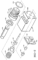
- the dispenser 10 includes a dispenser body 12, having an inlet 14 for receiving a source of fluid material, such as a hot melt adhesive.
- inlet 14 may be attached to a service module (not shown) having fluid passages therein for supplying fluid and containing heaters and temperature sensors to maintain the temperature of the fluid entering inlet port 14.
- An O-ring 15a mounted within inlet port 14.
- the dispenser 10 may be mounted to the service block by mounting screws 17.
- the adapter body 16 is mounted within a cavity of the body 12 within a cavity of the body 12.
- the adapter body 16 has an outer annular groove 18, which is coupled to the inlet 14.
- the adapter body and the dispenser body form a fluid chamber 20.
- An O-ring 15b may be used to provide a seal between the adapter and dispenser bodies 16, 12. Fluid is transferred from the annular groove 18 to the fluid chamber 20 by fluid passageways 22 and 23.
- the fluid chamber 20 is coupled to the discharged outlet 24 via an axially extending fluid passageway 26.
- a nozzle adapter 28 Attached to the dispenser body 12 is a nozzle adapter 28.
- the nozzle adapter may be mounted to the dispenser body by screws (not shown) extending through openings 30A, 30B, respectively.
- the outer periphery of the nozzle adapter 28 may have threads 31 for receiving a nozzle, not shown.
- a plunger 32 Located within the fluid chamber 20 and the fluid passageway 26 is a plunger 32, which is slidably mounted for reciprocal motion.
- the plunger 32 has a valve needle 34, such as a ball, located at one end of the plunger 32 for mating with a seat 36, located within the nozzle adapter 28, in the closed position.
- An insert 38 aligns the seat 36 and the nozzle adapter 28 with the fluid passageway 26 in dispenser body 12.
- the insert 38 may have point guide contacts, for guiding the plunger into the seat 36 as the plunger 32 moves from an open position to a closed position.
- the electromagnetic coil assembly 42 is enclosed by housing 44.
- the electromagnetic coil assembly generates an electromagnetic field when it is subjected to a source of electrical power (not shown).
- the electromagnetic coil assembly 42 includes a coil 46 comprising a plurality of windings wrapped around a bobbin or spool 48.
- the windings of the coil 46 may be encased in a potting layer.
- this potting material has a high thermal conductivity in order to transfer the heat generated by the coil to the housing 44, for eventual dissipation to the surrounding ambient air.
- the spool 48 is located around a pole piece 50 and may be attached to one another, such by potting.
- the pole piece 50 is generally cylindrical in shape having an end 52 in fluid communication with the fluid chamber 20.
- Preferably the pole piece 50 extends axially from the spool such that the spool is spaced from the fluid chamber 20.
- a ring 54 may be located about the periphery of and brazed to, the pole piece 50 to maintain the spacing between the pole piece and the adapter body 16. The interaction of the pole piece 50, ring 54 and the adapter body 16 provide a seal to prevent the flow of fluid material from contacting the spool and in turn the coil 46.
- the ring 54 is of a material which is non-magnetic so as to help prevent the magnetic field from passing through it.
- the ring 54 also provides spacing between the coil and the adapter body. It is therefore preferred that the ring 54 does not readily transfer heat therethrough so as not to readily transfer heat to the coil. It has been found that a ring 54 manufactured out of 300 series stainless steel performs these functions adequately. It is also preferred, to provide further insulation between the coil and the heated fluid in order to further limit the transfer of heat to the coil. This can be accomplished by providing an air gap 55 between the ring 54 and the spool 48.
- the spool 48 may include a raised annular portion 48A to provided spacing between the spool and the ring 54.
- This spacing results in an air gap directly between the spool and the ringer 54, and indirectly between the spool and the fluid chamber.
- the windings of the coil 46 are both physically and thermally isolated from the fluid material.
- other insulation materials such as fiberglass, for example, can be used to help insulate the coil.
- the pole piece 50 is a fixed pole. In other words, when the coil 46 is energized it is not driven axially but is retained in its position. In contrast, the plunger 32 is a movable member.
- the generated magnetic field Upon energization of the coil 46, the generated magnetic field will establish a pole (north or south) on the end 52 of the pole 50. Likewise, a pole of opposite polarity to that established on end 52 of pole 50 will be established on the head 62 of the plunger 32. This will cause plunger 32 to be attracted to the fixed pole 50. As the plunger 32 moves toward the fixed pole 50 the valve needle 34 is moved from the seat 36 which allows the adhesive to be dispensed from the outlet 24. When the coil is de-energized and the field collapses, the plunger 32 will be moved back to the closed position by a spring 56. The spring 56 extends between arms of a retainer 58, attached to the plunger 32, and a shoulder 60 of the adapter body 16.
- the head 62 of the plunger 32 has a diameter which closely approximates that of the diameter of the fluid chamber in the portion in which the head 62 slidably moves. This helps to keep the plunger properly aligned as it slides back and forth. While a close fit provides for good guiding of the plunger, it does not provide a good flow path for the material. Therefore, in order to allow for the fluid material to flow past the head, bypass channels 64 are provided in the adapter body.
- Causing the fluid to flow past the plunger in this manner helps to prevent dead spots from occurring in the flow of the adhesive through the dispenser.
- the fluid may begin to solidify to produce undesirable particles or chunks, commonly know as char.
- the flow path through channels 22 and around the plunger head via channels 64 may result in excessive pressure drops across the plunger. In such instances, the pressure drop across the head of the plunger may be reduced by shunting some of the adhesive directly into the fluid chamber 20 from the outer annular groove 18 via channels 23.
- the face 70 of the head 62 of the plunger 32 When dispensing, the face 70 of the head 62 of the plunger 32 will be adjacent to and/or in contact with the end 52 of the fixed pole 50. Fluid material trapped between face 70 of the plunger head 62 and the end 52 of the fixed pole will contribute to an increase in the force required to begin to move the plunger to the closed position and/or will cause the closing response time to increase. This phenomenon is similar to the increase in force that is required to separate two pieces of glass which have a drop of fluid placed in between them. As used herein, this phenomenon will be referred to as squeeze film lubrication.
- a means for introducing a flow of fluid between the pole 50 and the plunger 32 to provide vacuum relief may be accomplished by providing the head 62 with fluid flow channels 66, 68.
- Flow channel 66 extends axially from the face 70, closest to the pole 50. Intersecting with this channel is a radially extending channel 68 which opens into the chamber 20.
- fluid will be directed into the openings of fluid channel 68, into fluid channel 66, and eventually into the area 74, which is formed between the fixed pole 50 and the plunger head 62, as well as between the raised portions 72.
- the introduction of fluid into area 74 from channels 66 and 68 reduces the vacuum like attraction force between the pole and the plunger as the plunger is being driven to the closed position.
- this flow path 66, 68 helps in decreasing the response time necessary to move the plunger to the open position.
- the plunger moves from the closed to the open position, there is fluid between the head 62 of the plunger and the fixed pole piece 50 which must be displaced.
- the head acting much like a piston will displace fluid through the bypass channels 64, as well as through flow channels 66 and 68, and into the fluid chamber 20.
- the amount of fluid which must be displaced is now the volume of fluid contained within the area 74.
- Fixed pole 50 may be provided with a bore 76. Contained within this bore is a non-magnetic material, such as 300 series stainless steel, brass, etc., which effectively prevents the adhesive from traveling into the interior of the fixed pole.
- the non-magnetic material within the bore 76 helps concentrate the magnetic flux generated by the coil on the pole face 52 of the pole 50 by reducing the cross-sectional area of the magnetic portion of the pole 50 which is perpendicular to the lines of flux.
- the coil assembly 42 may be retained within the assembly by a set screw 78.
- the windings of the coil 46 may be coupled to a source of electrical power by electrical conductors passing through a bore (not shown) to a respective electrical stud, such as illustrated at 80. Eash of the studs 80, connect to female couplings 81 carried by an electrical connector 83.
- the female couplings 81 may be connected to the electrical conductors (not shown) of a cord set extending from port 82.
- the connector 83 may be retained to the coil housing by a screw 84.
- coil housing 44 may be provided with a plurality of fins 86 for dissipating the heat generated within the dispenser.
- the fins 86 of the heat sink 88 are thermally coupled to electromagnetic coil assembly 42.
- heat generated by the coil assembly 42 will be thermally transferred through the coil housing 44 and to the fins 86.
- the coil housing 44 directs heat away from the coil assembly 42, it is preferred that it is of a material that is fairly thermally conductive.
- coil housing 44 is also of a material which will help direct the field generated by the coil 46.
- the housing is of a magnetic material, such as a ferro magnetic material.
- the heat sink and the housing 44 may be one piece, they could be two separate pieces.
- a dispenser has been built wherein good results have been obtained with aluminum heat sinks attached to the coil housing 44.
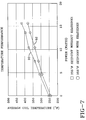
- FIG. 7 there is illustrated a graph of the temperature of the coil of an electric dispenser versus the power utilized by the coil.
- the electric dispenser according to an embodiment of the invention was equipped with detachable aluminum heat sinks. The temperature of the coil was monitored at various power levels both with and without the heat sinks attached to the housing of the dispenser. The application temperature of the adhesive during this experiment was 355°F while the ambient temperature was approximately 70°F. The temperature plotted on each curve is an average of all temperatures taken at that particular power level.
- the graph of the temperature without heat sinks is illustrated by line 90 while that of the temperature with heat sinks is illustrated by line 92.
- the temperature differential between the two lines becomes generally greater.
- the benefit of the heat sinks becomes more and more apparent. Being able to operate at higher power levels allows the coil to be driven open/closed faster, thereby allowing the dispenser to operate at faster cycle times.
- the plunger is a ferromagnetic material, such as steel, it is preferable to match the thermal expansion coefficient of the various parts which the plunger inter-reacts with, such as the body 12, seat, etc. Due to the heat fluid material and/or its associated heaters, these materials are going to expand. At higher application temperatures this expansion becomes greater. If aluminum is used, for the body, it will expand faster than that of the plunger. This may cause air gap variations. Therefore, it is preferred that the body 12 and the plunger 32 are made from the same materials or from materials which have the same or close coefficients of thermal expansions.
- the body 12 and the adapter body 16 out of stainless steel not only helps maintain the magnetic air gap at varying temperatures, but also allows for a more compact unit.
- hot melt adhesive dispensing systems can operate at relatively high pressures, such as for example, between 1000-1500 psi, the bodies 12 and 16 must be able to withstand such pressures.
- Bodies manufactured from aluminum would require greater cross-sectional areas than those manufactured from steel. As a result, a smaller and more compact unit may be produced by utilizing steel for the bodies 12 and 16.
Landscapes
- Engineering & Computer Science (AREA)
- Mechanical Engineering (AREA)
- Coating Apparatus (AREA)
Applications Claiming Priority (2)
| Application Number | Priority Date | Filing Date | Title |
|---|---|---|---|
| US08/144,893 US5375738A (en) | 1993-10-27 | 1993-10-27 | Apparatus for dispensing heated fluid materials |
| US144893 | 1993-10-27 |
Publications (2)
| Publication Number | Publication Date |
|---|---|
| EP0650770A2 true EP0650770A2 (fr) | 1995-05-03 |
| EP0650770A3 EP0650770A3 (fr) | 1995-11-22 |
Family
ID=22510613
Family Applications (1)
| Application Number | Title | Priority Date | Filing Date |
|---|---|---|---|
| EP94115641A Ceased EP0650770A3 (fr) | 1993-10-27 | 1994-10-05 | Appareil de distribution de produit fluide chauffé. |
Country Status (7)
| Country | Link |
|---|---|
| US (1) | US5375738A (fr) |
| EP (1) | EP0650770A3 (fr) |
| JP (1) | JPH07185428A (fr) |
| KR (1) | KR950011323A (fr) |
| AU (1) | AU675351B2 (fr) |
| CA (1) | CA2133536A1 (fr) |
| TW (1) | TW312683B (fr) |
Cited By (1)
| Publication number | Priority date | Publication date | Assignee | Title |
|---|---|---|---|---|
| CN110732465A (zh) * | 2019-11-22 | 2020-01-31 | 成都凯天电子股份有限公司 | 线圈密封胶灌封装置 |
Families Citing this family (51)
| Publication number | Priority date | Publication date | Assignee | Title |
|---|---|---|---|---|
| US5535919A (en) * | 1993-10-27 | 1996-07-16 | Nordson Corporation | Apparatus for dispensing heated fluid materials |
| DE4411569C1 (de) * | 1994-04-02 | 1995-07-20 | Itw Dynatec Gmbh Klebetechnik | Auftragskopf zur dosierten Abgabe von strömenden Medien |
| USD365830S (en) | 1994-10-31 | 1996-01-02 | Nordson Corporation | Fluid dispensing module for dispensing heated fluids, such as hot melt adhesives, sealants, or caulks |
| US5907339A (en) * | 1994-11-10 | 1999-05-25 | Diagraph Corporation | Ink jet printhead having solenoids controlling ink flow |
| US5791531A (en) * | 1996-04-12 | 1998-08-11 | Nordson Corporation | High speed fluid dispenser having electromechanical valve |
| US5915591A (en) * | 1997-09-10 | 1999-06-29 | Illinois Tool Works Inc. | Electric solenoid valve for hot melt adhesive and method therefor |
| US5875922A (en) * | 1997-10-10 | 1999-03-02 | Nordson Corporation | Apparatus for dispensing an adhesive |
| US6152386A (en) * | 1998-11-06 | 2000-11-28 | Nordson Corporation | Handgun and hose assembly for dispensing liquids |
| US6061225A (en) * | 1999-05-03 | 2000-05-09 | Nordson Corporation | Method and apparatus for controlling a solenoid within an electric dispensing gun |
| US6499629B1 (en) * | 1999-05-28 | 2002-12-31 | Nordson Corporation | Dispensing apparatus for viscous liquids |
| US6401976B1 (en) * | 2000-03-23 | 2002-06-11 | Nordson Corporation | Electrically operated viscous fluid dispensing apparatus and method |
| US7289878B1 (en) | 2000-05-15 | 2007-10-30 | Nordson Corporation | Apparatus and method for modifying operation of an electric gun driver |
| US6761290B2 (en) * | 2000-05-16 | 2004-07-13 | Nordson Corporation | Device for applying fluid material on a substrate, and application valve |
| KR100505180B1 (ko) * | 2002-02-20 | 2005-08-01 | 엘지.필립스 엘시디 주식회사 | 노즐세정장치를 구비한 액정적하장치 및 액정적하방법 |
| US8069653B2 (en) * | 2002-10-16 | 2011-12-06 | Nordson Corporation | Interchangeable nozzle for a dispensing module |
| US6994234B2 (en) * | 2003-04-03 | 2006-02-07 | Nordson Corporation | Electrically-operated dispensing module |
| US7021330B2 (en) | 2003-06-26 | 2006-04-04 | Planar Systems, Inc. | Diaphragm valve with reliability enhancements for atomic layer deposition |
| US6941963B2 (en) * | 2003-06-26 | 2005-09-13 | Planar Systems, Inc. | High-speed diaphragm valve for atomic layer deposition |
| US6907897B2 (en) * | 2003-06-26 | 2005-06-21 | Planar Systems, Inc. | Diaphragm valve for high-temperature precursor supply in atomic layer deposition |
| US7296706B2 (en) * | 2004-02-24 | 2007-11-20 | Nordson Corporation | Method and system for supporting and/or aligning components of a liquid dispensing system |
| USD536421S1 (en) | 2004-04-02 | 2007-02-06 | Nordson Corporation | Intake portion of a liquid dispensing valve |
| US7178704B2 (en) * | 2004-04-15 | 2007-02-20 | Nordson Corporation | Electrically-operated dispenser |
| US20060097010A1 (en) * | 2004-10-28 | 2006-05-11 | Nordson Corporation | Device for dispensing a heated liquid |
| US7296707B2 (en) * | 2004-06-10 | 2007-11-20 | Graco Minnesota Inc. | Method and apparatus for dispensing a hot-melt adhesive |
| JP4123384B2 (ja) * | 2004-09-13 | 2008-07-23 | 株式会社デンソー | 燃料噴射弁 |
| US7214885B2 (en) * | 2004-09-29 | 2007-05-08 | Nordson Corporation | Liquid dispensing system having a modular cord set |
| US7278550B2 (en) * | 2004-11-11 | 2007-10-09 | Nordson Corporation | Method and system for aligning components of a liquid dispensing system |
| US7414532B2 (en) * | 2005-04-20 | 2008-08-19 | Nordson Corporation | Method of attaching RFID tags to substrates |
| JP2007046499A (ja) * | 2005-08-08 | 2007-02-22 | Toyota Motor Corp | 電磁駆動弁 |
| US20070290382A1 (en) * | 2006-06-14 | 2007-12-20 | Marc Laverdiere | Systems and methods for managing heat transfer in a fluid handling device |
| US20090124996A1 (en) * | 2006-11-03 | 2009-05-14 | Scott Heneveld | Apparatus and methods for injecting high viscosity dermal fillers |
| JP2010022881A (ja) * | 2007-03-30 | 2010-02-04 | Musashi Eng Co Ltd | 液材吐出装置および液材吐出方法 |
| KR100886160B1 (ko) * | 2007-07-09 | 2009-02-27 | 곽인숙 | 마그네틱 니들밸브 |
| JP5735516B2 (ja) | 2009-09-21 | 2015-06-17 | ノードソン コーポレーションNordson Corporation | 空気圧作動式液体吐出弁 |
| US8210398B2 (en) | 2010-06-29 | 2012-07-03 | Nordson Corporation | Thermally insulated applicator |
| USD647380S1 (en) | 2010-06-29 | 2011-10-25 | Nordson Corporation | Cover for an adhesive dispensing gun |
| EP2771126B1 (fr) | 2011-10-27 | 2019-09-18 | Graco Minnesota Inc. | Dispositif de fusion |
| US9174231B2 (en) | 2011-10-27 | 2015-11-03 | Graco Minnesota Inc. | Sprayer fluid supply with collapsible liner |
| USD678374S1 (en) | 2012-10-26 | 2013-03-19 | Nordson Corporation | Wall mounted adhesive melter |
| US8939330B2 (en) | 2013-03-13 | 2015-01-27 | Graco Minnesota Inc. | Removable module service seat |
| US10086399B2 (en) * | 2014-03-21 | 2018-10-02 | Faulhaber Precistep Sa | Device for administering a fluid product |
| US9796492B2 (en) | 2015-03-12 | 2017-10-24 | Graco Minnesota Inc. | Manual check valve for priming a collapsible fluid liner for a sprayer |
| US10072768B1 (en) * | 2015-06-18 | 2018-09-11 | Jansen's Aircraft Controls Systems, Inc. | Thermo-stratified, passive-cooled servo valve |
| WO2017010451A1 (fr) * | 2015-07-16 | 2017-01-19 | 大川原化工機株式会社 | Disperseur par voie humide |
| US10016780B2 (en) * | 2016-05-12 | 2018-07-10 | Illinois Tool Works Inc. | System of dispensing material on a substrate with a solenoid valve of a pneumatically-driven dispensing unit |
| KR102392753B1 (ko) * | 2017-09-25 | 2022-05-03 | 주식회사 만도 | 브레이크 시스템용 솔레노이드 밸브 |
| US10933435B2 (en) * | 2017-12-21 | 2021-03-02 | The Boeing Company | Apparatuses for depositing an extrudable substance onto a surface |
| PL3747551T3 (pl) * | 2018-02-02 | 2025-05-26 | Threebond Co., Ltd. | Urządzenie uwalniające i sposób dostarczania cieczy |
| CN115739435A (zh) | 2019-05-31 | 2023-03-07 | 固瑞克明尼苏达有限公司 | 手持式流体喷雾器 |
| DE102021208742A1 (de) * | 2021-08-11 | 2023-02-16 | Robert Bosch Gesellschaft mit beschränkter Haftung | Magnetspule mit Kühlstruktur und Magnetventil mit derartiger Magnetspule |
| CN119010497B (zh) * | 2024-10-23 | 2025-01-07 | 常州市美特精密电机有限公司 | 一种电机自动组装点胶生产线 |
Family Cites Families (38)
| Publication number | Priority date | Publication date | Assignee | Title |
|---|---|---|---|---|
| US1504773A (en) * | 1922-03-31 | 1924-08-12 | Marston Sheldon | Electromagnetic valve |
| US3212715A (en) * | 1963-06-19 | 1965-10-19 | Eric H Cocks | Solenoid airless spray gun |
| US3329347A (en) * | 1965-10-19 | 1967-07-04 | Vitramon Inc | Valved liquid ejector capable of emitting intermittent spurts |
| US3408008A (en) * | 1966-12-02 | 1968-10-29 | Eric H. Cocks | Apparatus for applying hot melt adhesives |
| US3463363A (en) * | 1967-10-12 | 1969-08-26 | Fusion Inc | Applicator gun |
| US3485417A (en) * | 1968-06-19 | 1969-12-23 | Eric H Cocks | Hand-held applicator for hot-melt adhesives |
| US3593241A (en) * | 1969-07-18 | 1971-07-13 | Alfred J Ludwig | Solenoid valve having a slotted flux sleeve for nesting the winding leads |
| FR2079805A5 (fr) * | 1970-02-13 | 1971-11-12 | Roto Diesel Sa | |
| DE2062420A1 (de) * | 1970-12-18 | 1972-06-22 | Bosch Gmbh Robert | Elektromagnetisch betätigbares Kraftstoff-Einspritzventil für eine Brennkraftmaschine |
| US3704833A (en) * | 1971-02-17 | 1972-12-05 | Fred O Wheat | Solenoid valve assembly |
| DE2110596B2 (de) * | 1971-03-05 | 1978-10-05 | Robert Bosch Gmbh, 7000 Stuttgart | Magnetventil |
| DE2161605A1 (de) * | 1971-12-11 | 1973-06-14 | Linde Ag | Magnetventil |
| US3936030A (en) * | 1972-05-08 | 1976-02-03 | Itt Industries, Inc. | Electromagnetic valve |
| DE2222448A1 (de) * | 1972-05-08 | 1973-11-22 | Teves Gmbh Alfred | Elektromagnetisches ventil |
| US3827604A (en) * | 1972-09-11 | 1974-08-06 | Nordson Corp | Modular solenoid-operated dispenser |
| US3811601A (en) * | 1972-09-11 | 1974-05-21 | Nordson Corp | Modular solenoid-operated dispenser |
| FR2207435A5 (fr) * | 1972-11-17 | 1974-06-14 | Wittenberge Gulliez Juli | |
| US3965377A (en) * | 1973-06-21 | 1976-06-22 | Carbonneau Industries, Inc. | Linear force generator |
| DE2458728A1 (de) * | 1974-12-12 | 1976-06-24 | Bosch Gmbh Robert | Elektromagnetisch betaetigbares einspritzventil |
| US4044324A (en) * | 1976-04-30 | 1977-08-23 | Ledex, Inc. | Coil compressed plunger cavity components for a wet type solenoid |
| US4218669A (en) * | 1978-09-13 | 1980-08-19 | SR Engineering | Adjustable short stroke solenoid |
| US4295631A (en) * | 1980-03-21 | 1981-10-20 | Allen Walter E | Solenoid operated valve |
| ATE17883T1 (de) * | 1981-04-29 | 1986-02-15 | Solex Uk Ltd | Eine elektromagnetische f luessigkeitseinspritzvorrichtung und ein einzelpunktkraftstoffeinspritzsystem fuer eine verbrennungskraftmaschine. |
| US4453652A (en) * | 1981-09-16 | 1984-06-12 | Nordson Corporation | Controlled current solenoid driver circuit |
| US4437488A (en) * | 1982-05-24 | 1984-03-20 | Lockwood Technical Inc. | Solenoid valve for hot melt material |
| US4488665A (en) * | 1982-05-24 | 1984-12-18 | Spraymation, Inc. | Multiple-outlet adhesive applicator apparatus and method |
| US4981281A (en) * | 1983-12-21 | 1991-01-01 | Robert W. Brundage | Solenoid controlled fluid flow valve |
| DE3604436A1 (de) * | 1986-02-13 | 1987-08-20 | Bosch Gmbh Robert | Elektromagnet fuer kraftstoffeinspritzanlagen |
| DE3641470A1 (de) * | 1986-12-04 | 1988-06-16 | Bosch Gmbh Robert | Elektromagnetisch betaetigbares kraftstoffeinspritzventil |
| US5022629A (en) * | 1988-01-04 | 1991-06-11 | Interface, Inc. | Valve construction |
| US4981280A (en) * | 1989-04-27 | 1991-01-01 | The Aro Corporation | Solenoid actuated fluid valve |
| US4962871A (en) * | 1989-07-24 | 1990-10-16 | Valco Cincinnati, Inc. | Applicator utilizing high speed non-contact extrusion valve |
| DE3930785C1 (fr) * | 1989-09-14 | 1991-03-07 | Danfoss A/S, Nordborg, Dk | |
| US4951917A (en) * | 1989-12-06 | 1990-08-28 | Slautterback Corporation | Dynamic response time for electromagnetic valving |
| US5010911A (en) * | 1989-12-15 | 1991-04-30 | Wormald U.S., Inc. | Electromagnetic valve operator |
| JP2518031Y2 (ja) * | 1990-12-19 | 1996-11-20 | 株式会社ユニシアジェックス | 燃料噴射弁 |
| US5192936A (en) * | 1991-08-22 | 1993-03-09 | Mac Valves, Inc. | Solenoid |
| JP3114826B2 (ja) * | 1992-07-01 | 2000-12-04 | ダイワ精工株式会社 | 釣竿とその製造方法 |
-
1993
- 1993-10-27 US US08/144,893 patent/US5375738A/en not_active Expired - Fee Related
-
1994
- 1994-10-03 CA CA002133536A patent/CA2133536A1/fr not_active Abandoned
- 1994-10-05 EP EP94115641A patent/EP0650770A3/fr not_active Ceased
- 1994-10-19 AU AU75937/94A patent/AU675351B2/en not_active Ceased
- 1994-10-24 TW TW083109855A patent/TW312683B/zh active
- 1994-10-27 KR KR1019940027553A patent/KR950011323A/ko not_active Withdrawn
- 1994-10-27 JP JP6263327A patent/JPH07185428A/ja not_active Withdrawn
Cited By (1)
| Publication number | Priority date | Publication date | Assignee | Title |
|---|---|---|---|---|
| CN110732465A (zh) * | 2019-11-22 | 2020-01-31 | 成都凯天电子股份有限公司 | 线圈密封胶灌封装置 |
Also Published As
| Publication number | Publication date |
|---|---|
| EP0650770A3 (fr) | 1995-11-22 |
| US5375738A (en) | 1994-12-27 |
| CA2133536A1 (fr) | 1995-04-28 |
| AU675351B2 (en) | 1997-01-30 |
| JPH07185428A (ja) | 1995-07-25 |
| AU7593794A (en) | 1995-05-18 |
| KR950011323A (ko) | 1995-05-15 |
| TW312683B (fr) | 1997-08-11 |
Similar Documents
| Publication | Publication Date | Title |
|---|---|---|
| US5375738A (en) | Apparatus for dispensing heated fluid materials | |
| US5535919A (en) | Apparatus for dispensing heated fluid materials | |
| US5405050A (en) | Electric dispenser | |
| EP0908240B1 (fr) | Appareil pour délivrer un adhésif | |
| US5791531A (en) | High speed fluid dispenser having electromechanical valve | |
| EP1241359B1 (fr) | Soupape à actionneur et dissipateur de chaleur | |
| JP2001263525A (ja) | 粘性流体アプリケータ用弁 | |
| CN113669462B (zh) | 一种低功耗的双稳态电磁阀 | |
| AU600101B2 (en) | Pilot operated coolant control valves in manifold assembly | |
| US9328841B2 (en) | Fluid dispenser utilizing dual coils and methods of fluid dispensing | |
| SE470025B (sv) | Elektriskt manövrerad ventil och sätt för sammansättning därav | |
| CN107246497B (zh) | 自保持式电磁阀 | |
| CN102753870B (zh) | 用于安装在安装块中的可电磁切换的阀 | |
| CN102762904B (zh) | 用于安装在安装块中的可电磁切换的阀 | |
| EP1169135A1 (fr) | Appareil de distribution a actionnement electrique et procede de distribution de liquide visqueux | |
| CN213017866U (zh) | 一种微型电磁阀 | |
| GB2096283A (en) | Electro-fluid control device | |
| JP2005061443A (ja) | 電磁式比例弁 | |
| GB2485440A (en) | A seal assembly for a metering valve | |
| CN110094570B (zh) | 电磁三位三通阀 | |
| EP1251302A2 (fr) | Appareil de distribution de liquides visqueux | |
| CN117869646A (zh) | 一种航天器用卸荷式用永磁自锁电磁阀 | |
| CN106678431B (zh) | 一种常开电磁控制阀 | |
| US20060266965A1 (en) | Electromagnetically actuated pivot valve assembly | |
| WO1982003431A1 (fr) | Dispositif de commande electro-fluide |
Legal Events
| Date | Code | Title | Description |
|---|---|---|---|
| PUAI | Public reference made under article 153(3) epc to a published international application that has entered the european phase |
Free format text: ORIGINAL CODE: 0009012 |
|
| AK | Designated contracting states |
Kind code of ref document: A2 Designated state(s): CH DE ES FR GB IT LI NL SE |
|
| PUAL | Search report despatched |
Free format text: ORIGINAL CODE: 0009013 |
|
| AK | Designated contracting states |
Kind code of ref document: A3 Designated state(s): CH DE ES FR GB IT LI NL SE |
|
| 17P | Request for examination filed |
Effective date: 19960517 |
|
| 17Q | First examination report despatched |
Effective date: 19980522 |
|
| STAA | Information on the status of an ep patent application or granted ep patent |
Free format text: STATUS: THE APPLICATION HAS BEEN REFUSED |
|
| 18R | Application refused |
Effective date: 20000821 |