EP0650771A2 - Auftragsgerät für Klebstoff - Google Patents
Auftragsgerät für Klebstoff Download PDFInfo
- Publication number
- EP0650771A2 EP0650771A2 EP94117094A EP94117094A EP0650771A2 EP 0650771 A2 EP0650771 A2 EP 0650771A2 EP 94117094 A EP94117094 A EP 94117094A EP 94117094 A EP94117094 A EP 94117094A EP 0650771 A2 EP0650771 A2 EP 0650771A2
- Authority
- EP
- European Patent Office
- Prior art keywords
- body member
- distal end
- end portion
- inner core
- glue applicator
- Prior art date
- Legal status (The legal status is an assumption and is not a legal conclusion. Google has not performed a legal analysis and makes no representation as to the accuracy of the status listed.)
- Withdrawn
Links
Images


Classifications
-
- B—PERFORMING OPERATIONS; TRANSPORTING
- B43—WRITING OR DRAWING IMPLEMENTS; BUREAU ACCESSORIES
- B43M—BUREAU ACCESSORIES NOT OTHERWISE PROVIDED FOR
- B43M11/00—Hand or desk devices of the office or personal type for applying liquid, other than ink, by contact to surfaces, e.g. for applying adhesive
- B43M11/06—Hand-held devices
- B43M11/08—Hand-held devices of the fountain-pen type
Definitions
- the present invention is directed to a glue or solvent bonder applicator for storing and applying a liquid glue or solvent bonder material. More specifically, the invention is directed to a glue applicator device that is particularly useful during the assembly of polystyrene plastic model kits.
- Such devices typically include a flexible body or tube portion that is squeezed to force a liquid glue or bonder material contained therein through a nozzle having a relatively small opening. Such devices may include an internal valve to control the flow of materials that may be actuated by the application of a force thereto.
- Such devices may include an internal valve to control the flow of materials that may be actuated by the application of a force thereto.
- Other similar devices that have a substantially rigid body that rely on gravity to direct the liquid material through a distal opening. Such devices have been provided with brushes and fibrous tips to facilitate application of the liquid glue or bonder material.
- an improved glue applicator device for storing and applying a liquid glue or bonder material that provides constant glue or bonder availability at the delivery tip without the use of an internal valve. It is desirable that such a device be able to instantly make available extra glue or bonder material at the point of application. It is further desirable that the device have a delivery tip that remains constantly moist with glue or bonder material so that it is ready for use without having to be primed. It is also desirable that the device be ergonomically designed in order to facilitate the delivery of plastic model glue or bonder material to the model builder in a manner that ensures a clean and well-assembled model.
- the present invention provides an ergonomically designed glue applicator for storing and applying a liquid glue or bonder solvent material.
- the glue applicator includes an elongated generally cylindrical body member, a rigid elongated inner core member positioned within the body member, a fibrous tip member, a liquid glue or bonder material contained within the body member, and a means for sealing the distal end of the body member.
- the elongated body member has a closed proximal end portion and an open distal end portion.
- a squeezable portion located adjacent the distal end portion, is of increased cross-sectional dimension and may be deflected inwardly by a force applied by a finger.
- the squeezable portion is generally elliptical in transverse cross-section.
- a first section of the squeezable portion is convex in longitudinal cross-section and may be provided with a plurality of spaced apart projections extending outwardly therefrom.
- a second section of the squeezable portion is concave in longitudinal cross-section and may be provided with a plurality of spaced apart cavities formed therein.
- the inner core member is positioned within the body member and extends along substantially the entire length thereof.
- the inner core member comprises a pair of elongated, intersecting, perpendicular partition portions that are dimensioned to contact an inner surface of the body member.
- a plurality of longitudinally spaced apart rib portions project transversely from the longitudinal center of the body member toward an inner surface of the body member.
- the distal end portion of the inner core member is frusto-conical in shape and has an elongated cavity formed therein.
- a proximal end portion of the fibrous tip member is received within the cavity.
- a plurality of openings are formed in the inner core member so as to permit the passage of liquid glue from the body member therethrough into the cavity for contacting the fibrous tip member.
- the means for sealing the distal end of the body member comprises a seal ring portion formed adjacent a distal end portion of the inner core member that is dimensioned to sealingly engage an inner surface of the body member.
- a ferrule member having a female portion of a snap fit assembly is received by a male portion of a snap fit assembly formed on an external surface of a distal end portion of the body member for urging the ring portion into sealing contact with the inner surface of the body member.
- Applicator 10 constructed in accordance with the invention.
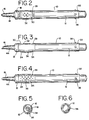
- Applicator 10 includes a body member 12, an inner core member 14, a fibrous tip member 16, a sealing ferrule member 18 and a protective cap member 20.
- Body member 12 is an elongated, generally cylindrical member having a closed proximal end portion 22 and a distal end portion 24.
- the distal end portion has a male portion 26 of a snap fit assembly formed integrally therewith.
- a squeezable portion 28, of generally elliptical transverse cross-section, is located adjacent distal end portion 24.
- Squeezable portion 28 includes a first section 30 that is generally convex in longitudinal cross-section, as best seen in FIG. 3.
- Section 30 has a plurality of spaced apart projections 32 extending outwardly therefrom.
- Squeezable portion 28 also includes a section 34 that is generally concave in longitudinal cross-section, as best seen in FIG. 3.
- Section 36 has a plurality of spaced apart cavities 36 formed therein.
- the first section 30 is diametrically opposed to the second section 34.
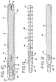
- a plurality of circumferentially spaced apart projections 38 extend outwardly from the outer surface of body member 12 adjacent to the proximal end portion 22. As best seen in FIG. 10, an internal alignment flange 40, is located at the proximal end portion 22.
- inner core member 14 has a proximal end portion 42 and a distal end portion 44.
- Distal end portion is frusto-conical in shape and defines a cavity 46 formed therein.
- Core member 14 includes a pair of elongated, intersecting partition portions 47 that are substantially perpendicular to each other. Partition portions 47 extend from the distal end portion 44 to the proximal end portion 42. A plurality of longitudinally spaced apart rib portions 48 project transversely from the longitudinal center line of the core member. The partition portions 47 extend a short distance beyond the outer edges of the rib portions 48. The rib portions are substantially rectangular in cross-section and the exposed corners thereof are beveled at 50. The spacing between immediately adjacent rib portions adjacent the proximal end of the core member is preferably reduced in the area in facing relationship with the squeezable portion 28.
- a section 52 of one of the partition portions 47 is cut-out at a proximal portion thereof so as to cooperate with the alignment flange 40 to orient the inner core member when it is inserted in the body member.
- a section 54 of one of the partition portions 46 is formed with a convex cross-section to cooperate with the first section 30 of squeezable portion 28.
- a seal ring portion 56 is formed adjacent the distal end portion of the inner core member for sealing contact with an inner surface of the body member. As best seen in FIG. 10, cavity 46 extends distally beyond seal ring portion 56.
- a plurality of openings 58 are formed through the partition portions 46 of the core member 14 to permit radial fluid communication between the body portion 12 and the cavity 46 therethrough. The openings 48 are located proximally of the seal ring portion 56.
- the body member 12 is preferably made from a relatively soft or flexible plastic material, such as low density polyethylene, having a nominal wall thickness of about .06 inches.
- the inner core member 14 is preferably formed from a substantially rigid plastic material, such as high density polyethylene or polypropylene.
- Inner core member 14 is positioned within body member 12 such that the alignment flange 40 is received by cut-out section 52. In so doing, section 54 of the inner core member is in transverse alignment with first section 30. The distal end portion 44 of the inner core member extends distally beyond the distal end of the body member 12 with the seal ring portion 56 in transverse alignment with the male portion 26. Fibrous tip member 16 is received within cavity 46 with the distal end thereof extending beyond the distal end of inner core member 14.
- ferrule member 18 has a proximal end portion 60 and a distal end portion 62.
- Proximal end portion 60 is provided with a female portion 64 of a snap fit assembly that receives the male portion 26 of body member 12.
- the seal ring portion 56 is urged into sealing engagement with the inner surface of the body portion.
- the distal end portion 44 of the inner core member 14 extends through an opening 66 formed through the distal end portion 62.
- cap member 20 includes a cylindrical chamber 80 formed therein that receives and sealingly engages the outer surface of the distal end portion 44 of the inner core member 14.
- the cap member 20 is dimensioned to be frictionally received by the outer surface of the proximal end portion 22 of the body member 12.
- Cap member 20 may be provided with a plurality of circumferentially spaced projections 70. Projections 38 and 70 prevent the application from rolling off a substantially horizontal surface.
- the body member 12 contains a suitable liquid glue or solvent bonder material of the type typically used for the assembly of polystyrene plastic members.
- the liquid glue or bonder material with body member 12 flows through opening 58 to maintain a constant supply thereof to the fibrous tip 16.
- the first section 30 is depressed the index finger causing an instantaneous surge of fluid flow into the cavity 46 and through the tip 16.
- the rigid inner core member 14 provides structural support for the soft body member 12 while permitting the flow of fluid from the body member to the fibrous tip 16.
Landscapes
- Coating Apparatus (AREA)
- Containers And Packaging Bodies Having A Special Means To Remove Contents (AREA)
Applications Claiming Priority (2)
| Application Number | Priority Date | Filing Date | Title |
|---|---|---|---|
| US08/147,157 US5358349A (en) | 1993-11-03 | 1993-11-03 | Glue applicator |
| US147157 | 1993-11-03 |
Publications (2)
| Publication Number | Publication Date |
|---|---|
| EP0650771A2 true EP0650771A2 (de) | 1995-05-03 |
| EP0650771A3 EP0650771A3 (de) | 1996-04-17 |
Family
ID=22520491
Family Applications (1)
| Application Number | Title | Priority Date | Filing Date |
|---|---|---|---|
| EP94117094A Withdrawn EP0650771A3 (de) | 1993-11-03 | 1994-10-28 | Auftragsgerät für Klebstoff. |
Country Status (8)
| Country | Link |
|---|---|
| US (1) | US5358349A (de) |
| EP (1) | EP0650771A3 (de) |
| JP (1) | JPH07256198A (de) |
| BR (1) | BR9404298A (de) |
| CA (1) | CA2130286A1 (de) |
| FI (1) | FI945161A7 (de) |
| NO (1) | NO944174L (de) |
| PL (1) | PL305672A1 (de) |
Cited By (1)
| Publication number | Priority date | Publication date | Assignee | Title |
|---|---|---|---|---|
| JP2016060133A (ja) * | 2014-09-19 | 2016-04-25 | 株式会社壽 | 液体塗布具 |
Families Citing this family (39)
| Publication number | Priority date | Publication date | Assignee | Title |
|---|---|---|---|---|
| USD362092S (en) | 1993-12-23 | 1995-09-05 | Wojciech Wasak | Cylindrical lens cleaner |
| USD359758S (en) | 1994-05-19 | 1995-06-27 | Pentel Of America, Ltd. | Grip for a writing instrument |
| CA2177210C (en) * | 1995-06-07 | 1999-08-31 | Rodney J. Baudino | Off-center point marker tip |
| US6676322B1 (en) * | 1995-06-07 | 2004-01-13 | Closure Medical Corporation | Impregnated applicator tip |
| DE69702237T2 (de) * | 1997-02-06 | 2000-12-21 | Tombow Pencil Co., Ltd. | Schreiberspitze für ein Markierungstift |
| USD403768S (en) * | 1997-05-09 | 1999-01-05 | Minnesota Mining And Manufacturing Company | Fiber tip applicator |
| US5984557A (en) * | 1998-04-22 | 1999-11-16 | Fennell; Forrest S | Glue guide |
| US6062753A (en) * | 1998-08-17 | 2000-05-16 | Pentech International Inc. | Writing instrument with enhanced tactile control and gripping comfort and method of making same |
| US6202897B1 (en) | 1998-08-25 | 2001-03-20 | 3M Innovative Properties Company | Unit dose liquid dispensing and packaging for dental application |
| US6283658B1 (en) * | 1999-06-30 | 2001-09-04 | Masheen, Inc. | Chapstick dispensing apparatus |
| USD477845S1 (en) | 2001-12-20 | 2003-07-29 | Nordson Corporation | Pen for dispensing a curable liquid |
| USD471586S1 (en) | 2002-06-03 | 2003-03-11 | Berol Corporation | Marker |
| USD471233S1 (en) | 2002-06-03 | 2003-03-04 | Berol Corporation | Grip for a marker |
| CA2457248C (en) | 2003-02-07 | 2012-07-17 | Closure Medical Corporation | Applicators, dispensers and methods for dispensing and applying adhesive material |
| USD500085S1 (en) | 2003-02-07 | 2004-12-21 | Closure Medical Corporation | Adhesive dispenser/applicator device |
| US20040190975A1 (en) * | 2003-02-07 | 2004-09-30 | Closure Medical Corporation | Applicators, dispensers and methods for dispensing and applying adhesive material |
| USD500084S1 (en) | 2003-07-10 | 2004-12-21 | Societe Bic | Applicator |
| USD493484S1 (en) | 2003-09-26 | 2004-07-27 | Elmer's Products, Inc. | Writing instrument |
| US7516872B2 (en) * | 2004-09-03 | 2009-04-14 | Closure Medical Corp. | Applicators, dispensers and methods for mixing, dispensing and applying adhesive or sealant material and another material |
| USD540470S1 (en) | 2004-09-03 | 2007-04-10 | Closure Medical Corporation | Adhesive dispenser/applicator device |
| US20060093427A1 (en) * | 2004-10-29 | 2006-05-04 | Timm Dale D Jr | Marker tip |
| TW200619051A (en) * | 2004-10-26 | 2006-06-16 | Hewlett Packard Development Co | Marker tip |
| US7596974B2 (en) | 2006-06-19 | 2009-10-06 | S.C. Johnson & Son, Inc. | Instant stain removing device, formulation and absorbent means |
| US8118508B2 (en) | 2006-11-30 | 2012-02-21 | Closure Medical Corporation | Dispenser with a frangible container and a rotating breaking member, for dispensing a polymerizable monomer adhesive |
| USD573710S1 (en) | 2006-11-30 | 2008-07-22 | Closure Medical Corporation | Dispenser |
| US8729121B2 (en) | 2007-06-25 | 2014-05-20 | Adhezion Biomedical, Llc | Curing accelerator and method of making |
| EP2742875B1 (de) | 2007-11-14 | 2016-02-24 | Adhezion Biomedical, LLC | Cyanoacrylgewebehaftstoffe |
| US8198344B2 (en) | 2008-06-20 | 2012-06-12 | Adhezion Biomedical, Llc | Method of preparing adhesive compositions for medical use: single additive as both the thickening agent and the accelerator |
| US8293838B2 (en) | 2008-06-20 | 2012-10-23 | Adhezion Biomedical, Llc | Stable and sterile tissue adhesive composition with a controlled high viscosity |
| US20110117047A1 (en) | 2008-06-23 | 2011-05-19 | Adhezion Biomedical, Llc | Cyanoacrylate tissue adhesives with desirable permeability and tensile strength |
| US9254133B2 (en) | 2008-10-31 | 2016-02-09 | Adhezion Biomedical, Llc | Sterilized liquid compositions of cyanoacrylate monomer mixtures |
| US8609128B2 (en) | 2008-10-31 | 2013-12-17 | Adhezion Biomedical, Llc | Cyanoacrylate-based liquid microbial sealant drape |
| US8652510B2 (en) | 2008-10-31 | 2014-02-18 | Adhezion Biomedical, Llc | Sterilized liquid compositions of cyanoacrylate monomer mixtures |
| USD643068S1 (en) * | 2010-05-07 | 2011-08-09 | Michael Wayne Teague | Highlighter nib |
| US9309019B2 (en) | 2010-05-21 | 2016-04-12 | Adhezion Biomedical, Llc | Low dose gamma sterilization of liquid adhesives |
| US8550737B2 (en) * | 2010-09-20 | 2013-10-08 | Adhezion Biomedical, Llc | Applicators for dispensing adhesive or sealant material |
| US9066711B2 (en) | 2011-11-02 | 2015-06-30 | Adhezion Biomedical, Llc | Applicators for storing sterilizing, and dispensing an adhesive |
| USD682938S1 (en) * | 2012-02-09 | 2013-05-21 | Target Brands, Inc. | Writing instrument |
| US9421297B2 (en) | 2014-04-02 | 2016-08-23 | Adhezion Biomedical, Llc | Sterilized compositions of cyanoacrylate monomers and naphthoquinone 2,3-oxides |
Family Cites Families (12)
| Publication number | Priority date | Publication date | Assignee | Title |
|---|---|---|---|---|
| US360298A (en) * | 1887-03-29 | Hezekiah hewitt | ||
| US190266A (en) * | 1877-05-01 | Improvement in fountain-pens | ||
| FR394069A (fr) * | 1908-09-09 | 1909-01-14 | Friedrich Max Rauschenbach | Humecteur pour timbres-poste, enveloppes, étiquettes et autres objets gommés |
| US3468611A (en) * | 1966-05-10 | 1969-09-23 | Lawrence T Ward | Liquid applicator |
| DE3010944C2 (de) * | 1980-03-21 | 1985-08-08 | Rotring-Werke Riepe Kg, 2000 Hamburg | Schreibgerät |
| DK315483A (da) * | 1982-07-17 | 1984-01-18 | Lingner & Fischer Gmbh | Dispenser til vaeskeformige klaebemidler |
| DE3420287C2 (de) * | 1983-06-03 | 1985-11-14 | Pilot Man-Nen Hitsu K.K., Tokio/Tokyo | Einsatz für ein Schreibgerät |
| JPS6145191U (ja) * | 1984-08-29 | 1986-03-25 | パイロツトインキ株式会社 | 筆記具 |
| US4770558A (en) * | 1986-02-20 | 1988-09-13 | Gebr. Schmidt KG Fabrik Fuer Feinmechanik | Ink writing or drawing instrument |
| DE3870453D1 (de) * | 1988-11-08 | 1992-05-27 | Sekisui Iko Co Ltd | Auftragegeraet fuer klebstoffe. |
| US5368810A (en) * | 1990-05-25 | 1994-11-29 | The Gillette Company | Method of manufacturing a fluid dispenser |
| JPH0749308B2 (ja) * | 1992-04-14 | 1995-05-31 | 積水アイコー株式会社 | ワンプッシュスクイズ式二重構造型接着剤包装容器 |
-
1993
- 1993-11-03 US US08/147,157 patent/US5358349A/en not_active Expired - Fee Related
-
1994
- 1994-08-17 CA CA002130286A patent/CA2130286A1/en not_active Abandoned
- 1994-10-28 EP EP94117094A patent/EP0650771A3/de not_active Withdrawn
- 1994-10-31 BR BR9404298A patent/BR9404298A/pt not_active Application Discontinuation
- 1994-11-02 PL PL94305672A patent/PL305672A1/xx unknown
- 1994-11-02 FI FI945161A patent/FI945161A7/fi unknown
- 1994-11-02 NO NO944174A patent/NO944174L/no unknown
- 1994-11-04 JP JP6271501A patent/JPH07256198A/ja active Pending
Cited By (1)
| Publication number | Priority date | Publication date | Assignee | Title |
|---|---|---|---|---|
| JP2016060133A (ja) * | 2014-09-19 | 2016-04-25 | 株式会社壽 | 液体塗布具 |
Also Published As
| Publication number | Publication date |
|---|---|
| EP0650771A3 (de) | 1996-04-17 |
| PL305672A1 (en) | 1995-05-15 |
| CA2130286A1 (en) | 1995-05-04 |
| US5358349A (en) | 1994-10-25 |
| NO944174L (no) | 1995-05-04 |
| BR9404298A (pt) | 1995-07-04 |
| NO944174D0 (no) | 1994-11-02 |
| FI945161L (fi) | 1995-05-04 |
| FI945161A7 (fi) | 1995-05-04 |
| JPH07256198A (ja) | 1995-10-09 |
| FI945161A0 (fi) | 1994-11-02 |
Similar Documents
| Publication | Publication Date | Title |
|---|---|---|
| US5358349A (en) | Glue applicator | |
| US4521128A (en) | Disposable toothbrush with cap | |
| US4640440A (en) | Foam dispensing device | |
| US5791801A (en) | Liquid applicator | |
| US5944698A (en) | Adjustable flow syringe | |
| US3541583A (en) | Aspirating device | |
| AU734535B2 (en) | Discharge device for flowable media using a thrust piston pump | |
| US6322542B1 (en) | Device for delivering liquid containing medicament | |
| US4747720A (en) | Sponge applicator and valve | |
| USRE37734E1 (en) | Dispensing bulb | |
| AU701047B2 (en) | Fluid pump without dead volume | |
| US6022504A (en) | Method of manufacturing a caulking nozzle | |
| US2577321A (en) | Nose drop dispenser | |
| US4801093B1 (en) | Push-nipple for medical sprayer | |
| US20130324948A1 (en) | Cotton balls, cotton swabs and cotton swab holder | |
| US3512526A (en) | Sponge sheath for douche tip | |
| US4138040A (en) | Dispenser for anaerobic and cyanoacrylate adhesives | |
| WO1996029252A1 (en) | Discharge nozzle | |
| US20050255425A1 (en) | Mixing tip for dental materials | |
| EP1355827B1 (de) | Behälter, verschlusskappe und verfahren zum verschliessen einer düsenspitze eines abgabebehälters für härtbare flüssigkeit | |
| US3968797A (en) | Disposable douche product | |
| CN107921213A (zh) | 具有改进的穿刺尖端的排放器 | |
| SE9702082D0 (sv) | Eye fluid applicator | |
| US11485548B1 (en) | Multi-use applicator and methods for its use | |
| US20180312309A1 (en) | Applicator with Breakaway Cap |
Legal Events
| Date | Code | Title | Description |
|---|---|---|---|
| PUAI | Public reference made under article 153(3) epc to a published international application that has entered the european phase |
Free format text: ORIGINAL CODE: 0009012 |
|
| AK | Designated contracting states |
Kind code of ref document: A2 Designated state(s): AT BE CH DE DK ES FR GB GR IE IT LI LU NL PT SE |
|
| PUAL | Search report despatched |
Free format text: ORIGINAL CODE: 0009013 |
|
| AK | Designated contracting states |
Kind code of ref document: A3 Designated state(s): AT BE CH DE DK ES FR GB GR IE IT LI LU NL PT SE |
|
| STAA | Information on the status of an ep patent application or granted ep patent |
Free format text: STATUS: THE APPLICATION IS DEEMED TO BE WITHDRAWN |
|
| 18D | Application deemed to be withdrawn |
Effective date: 19961018 |