EP0650776A1 - Dispositif pour réfroidir des bandes laminées - Google Patents
Dispositif pour réfroidir des bandes laminées Download PDFInfo
- Publication number
- EP0650776A1 EP0650776A1 EP94116695A EP94116695A EP0650776A1 EP 0650776 A1 EP0650776 A1 EP 0650776A1 EP 94116695 A EP94116695 A EP 94116695A EP 94116695 A EP94116695 A EP 94116695A EP 0650776 A1 EP0650776 A1 EP 0650776A1
- Authority
- EP
- European Patent Office
- Prior art keywords
- cooling
- gap
- segments
- media gap
- segment
- Prior art date
- Legal status (The legal status is an assumption and is not a legal conclusion. Google has not performed a legal analysis and makes no representation as to the accuracy of the status listed.)
- Granted
Links
- 238000001816 cooling Methods 0.000 title claims abstract description 65
- 238000005096 rolling process Methods 0.000 claims abstract description 6
- XAGFODPZIPBFFR-UHFFFAOYSA-N aluminium Chemical compound [Al] XAGFODPZIPBFFR-UHFFFAOYSA-N 0.000 claims abstract description 3
- 229910052782 aluminium Inorganic materials 0.000 claims abstract description 3
- 229910000831 Steel Inorganic materials 0.000 claims description 4
- 230000003993 interaction Effects 0.000 claims description 4
- 239000010959 steel Substances 0.000 claims description 4
- 230000007704 transition Effects 0.000 abstract description 3
- 239000004411 aluminium Substances 0.000 abstract 1
- 239000002826 coolant Substances 0.000 description 11
- 239000007921 spray Substances 0.000 description 3
- 230000009849 deactivation Effects 0.000 description 2
- 239000007788 liquid Substances 0.000 description 2
- 238000012423 maintenance Methods 0.000 description 2
- 238000000926 separation method Methods 0.000 description 2
- XLYOFNOQVPJJNP-UHFFFAOYSA-N water Substances O XLYOFNOQVPJJNP-UHFFFAOYSA-N 0.000 description 2
- 230000002411 adverse Effects 0.000 description 1
- 238000005553 drilling Methods 0.000 description 1
- 239000000839 emulsion Substances 0.000 description 1
- 238000005516 engineering process Methods 0.000 description 1
- 238000009434 installation Methods 0.000 description 1
- 230000000149 penetrating effect Effects 0.000 description 1
- 239000003208 petroleum Substances 0.000 description 1
- 239000010731 rolling oil Substances 0.000 description 1
- 238000007789 sealing Methods 0.000 description 1
Images

Classifications
-
- C—CHEMISTRY; METALLURGY
- C21—METALLURGY OF IRON
- C21D—MODIFYING THE PHYSICAL STRUCTURE OF FERROUS METALS; GENERAL DEVICES FOR HEAT TREATMENT OF FERROUS OR NON-FERROUS METALS OR ALLOYS; MAKING METAL MALLEABLE, e.g. BY DECARBURISATION OR TEMPERING
- C21D9/00—Heat treatment, e.g. annealing, hardening, quenching or tempering, adapted for particular articles; Furnaces therefor
- C21D9/52—Heat treatment, e.g. annealing, hardening, quenching or tempering, adapted for particular articles; Furnaces therefor for wires; for strips ; for rods of unlimited length
- C21D9/54—Furnaces for treating strips or wire
- C21D9/56—Continuous furnaces for strip or wire
- C21D9/573—Continuous furnaces for strip or wire with cooling
-
- B—PERFORMING OPERATIONS; TRANSPORTING
- B21—MECHANICAL METAL-WORKING WITHOUT ESSENTIALLY REMOVING MATERIAL; PUNCHING METAL
- B21B—ROLLING OF METAL
- B21B45/00—Devices for surface or other treatment of work, specially combined with or arranged in, or specially adapted for use in connection with, metal-rolling mills
- B21B45/02—Devices for surface or other treatment of work, specially combined with or arranged in, or specially adapted for use in connection with, metal-rolling mills for lubricating, cooling, or cleaning
- B21B45/0203—Cooling
- B21B45/0209—Cooling devices, e.g. using gaseous coolants
- B21B45/0215—Cooling devices, e.g. using gaseous coolants using liquid coolants, e.g. for sections, for tubes
- B21B45/0233—Spray nozzles, Nozzle headers; Spray systems
-
- C—CHEMISTRY; METALLURGY
- C21—METALLURGY OF IRON
- C21D—MODIFYING THE PHYSICAL STRUCTURE OF FERROUS METALS; GENERAL DEVICES FOR HEAT TREATMENT OF FERROUS OR NON-FERROUS METALS OR ALLOYS; MAKING METAL MALLEABLE, e.g. BY DECARBURISATION OR TEMPERING
- C21D1/00—General methods or devices for heat treatment, e.g. annealing, hardening, quenching or tempering
- C21D1/62—Quenching devices
- C21D1/667—Quenching devices for spray quenching
Definitions
- the invention relates to a device for cooling rolled strips, in particular for laminar strip cooling when rolling aluminum strips.
- the invention has for its object to make a device of the type mentioned maintenance and user friendly and more variable in terms of its uses.
- cooling segments closed on the outer sides with a cover have a media gap extending over their entire length and several cooling segments with a media gap which is transition-free from cooling segment to cooling segment can be arranged in a row.
- Media gap is understood here to be the outlet gap for the liquid cooling medium, for example rolling oil, water, etc.
- the covers which are advantageously flush, but leave the media gap free in a base body provided with a continuous, at least one supply connection and transition into the media gap, the cooling segment or the base body can end at the end, each cooling segment be easily tested for functionality before installation.
- the covers which are flush with the sides of the cooling segments but do not adversely affect the media gap, make it possible to string together several cooling segments with a laminar flow that is essentially transition-free at the separation points from cooling segment to cooling segment, i.e. the gaps of the individual cooling segments have no difference and are continuous to form a common media gap educated.
- the segment design allows the strip cooling to be variably adjusted to the width of the strip to be rolled, because it is only necessary to line up either more or fewer cooling segments.
- zone deactivation can be implemented very easily, namely by switching off the media supply to the cooling segments in question.
- the cooling segments In view of the cooling segments to be operated with low pressures (from 0.01 bar) for the cooling medium, seals can be omitted because the mechanical surface quality is sufficient for sealing. Finally, the laminar flow, which can be achieved virtually without transition when the cooling segments are placed next to one another, allows the cooling segments to be easily manufactured. In fact, their dimensions can be such that the distributor bore, which extends over the entire length of the base body, can be manufactured using conventional drilling technology. Maintenance and service are also made easier, as segment-by-segment replacement is possible.
- the base body has a cutout axially exposing the distributor bore with an oblique guide surface which, in interaction with a slide wedge having a corresponding guide surface and arranged in the cutout, forms the media gap. Due to the guiding surfaces, a long jet of the emerging cooling medium can be achieved, which favors the laminar flow of the medium as well as smooth surfaces of the media gap.
- the cooling segments can be arranged against the rolled strip from above and / or from below, for physical reasons advantageously from below, the distance from the rolled strip being approximately 50 to 100 mm.
- the gap width of the media gap on each cooling segment can be set individually, gap widths of 0 to 3 mm being able to be set.
- an optimized gap geometry and thus a quiet operation of the cooling segments is achieved.
- the slide wedge can be screwed in - in each case from the ends of the cooling segment - by screwing it in more or less move the set screw, which is designed as a grub screw, for example, and thus adjust the gap.
- Gauges or feeler gauges can be inserted between the guide surfaces to check the respective gap width.
- cooling segments be screwed together with a box-like steel structure.
- the cooling segments which can not only be strung together, but can also be arranged in any number one behind the other, are thus arranged on a support frame which, when a liquid is used as the cooling medium, serves at the same time to collect and return the cooling medium to be used in the circuit.
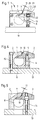
- a cooling segment 1 shown in FIG. 1 from its narrow or front side consists essentially of a cross section rectangular base body 2 (cf. FIGS. 4 and 5 in conjunction with FIG. 7) and an adjustable or adjustable slide wedge 3 arranged on the base body 2. This is fixed by means of screws 5 (cf. FIG. 4), which are provided by are used below in through bores 4 of the base body 2. The bores 4 are formed with sufficient radial clearance for actuating movements.
- the slide wedge 3 is inserted into a cutout 6 (see FIG. 7), which extends over the entire length of the base body 2 of the cooling segment 1; it projects with a flow nose 7 into a distributor bore 8 penetrating the base body 2 in the longitudinal direction (cf. FIGS. 4 and 5).
- the section 6 of the base body 2 which merges into the distribution bore 8 and exposes it axially, as shown in FIG.
- the slide wedge 3 which has a corresponding guide surface 10
- it forms a media gap 11 shown in FIGS. 4 and 5 in the basic setting, which can be varied by adjusting the slide wedge 3, through which the cooling medium emerges and is sprayed against a roller belt (not shown).
- the cooling medium for example water
- the connections 12 continue into a steel structure 13, which is only schematically indicated in the figures and is box-shaped and carries the cooling segments 1, and are connected to a coolant supply (not shown).
- the cooling segments 1 are, on the one hand, from FIG. 5, from above, through the slide wedge 3 and the base body 2, fastening screws 14 and, on the other hand, at the side facing away from the slide wedge 3, only through the base body 2, fastening screws 15 (see FIG. 4) screwed to the steel structure 13.
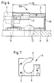
- the front or narrow sides of the cooling segment 1 are provided with lids 16 which are inserted flush with the end outer surfaces of the base body 2 in the base body 2 and which extend over the entire length 17 and 18 (see FIG. 6) of the Completely seal the cooling segment 1 or 100 (see FIG. 6) extending distributor bore 8 to the outside.
- the covers 16 are designed such that they end below the media gap 11 defined by the guide surfaces 9, 10, i.e. do not cover this (see Fig. 1).
- a cooling segment 1 of great length 17 is thus formed by a cooling segment 100 of shorter length 18 to cool the strip for a correspondingly wider rolled strip, the media gaps 11 go at the separation points between the one and the other cooling segment 1 or 100 (see FIG 2 and 6) without any difference in one another, and in this way a transition-free laminar flow can be maintained.
- cooling segment 1 Apart from the different length dimensions, there are no differences between the cooling segment 1 and the cooling segment 100 (see FIG. 6), although the shorter length 18 of the cooling segment 100 only requires a supply connection 12 for supplying the cooling medium into the distributor bore 8.
- the series of cooling segments 1, 100 possible with essentially seamless media gap 11 allows the respective segment width of the belt cooling to be easily adapted to the specific requirements, i.e. in particular to adjust the width of the rolled strip.
- the slide wedge 3 is adjustably arranged in the base body 2.
- insert blocks 19 are fastened to the two front ends of the base body and, as shown in FIG. 1, project with grooves 20 associated with them in the slide block 3 with projecting ends.
- a set screw 21 screwed into the projecting end of the block is accessible to an operator from outside through a bore 22, and according to the play or free space in the groove 20, the slide wedge 3 can be adjusted or removed from its guide surface 10 by turning the set screws 21 closer to the corresponding guide surface 9 of the base body 2, which is synonymous with a variable setting of the Media gap 11 is.
Landscapes
- Engineering & Computer Science (AREA)
- Chemical & Material Sciences (AREA)
- Mechanical Engineering (AREA)
- Physics & Mathematics (AREA)
- Thermal Sciences (AREA)
- Crystallography & Structural Chemistry (AREA)
- Materials Engineering (AREA)
- Metallurgy (AREA)
- Organic Chemistry (AREA)
- Heat Treatment Of Strip Materials And Filament Materials (AREA)
- Heat Treatments In General, Especially Conveying And Cooling (AREA)
- Metal Rolling (AREA)
Applications Claiming Priority (2)
| Application Number | Priority Date | Filing Date | Title |
|---|---|---|---|
| DE4337342 | 1993-11-02 | ||
| DE4337342A DE4337342A1 (de) | 1993-11-02 | 1993-11-02 | Vorrichtung zum Kühlen von Walzbändern |
Publications (2)
| Publication Number | Publication Date |
|---|---|
| EP0650776A1 true EP0650776A1 (fr) | 1995-05-03 |
| EP0650776B1 EP0650776B1 (fr) | 1997-06-18 |
Family
ID=6501599
Family Applications (1)
| Application Number | Title | Priority Date | Filing Date |
|---|---|---|---|
| EP94116695A Expired - Lifetime EP0650776B1 (fr) | 1993-11-02 | 1994-10-22 | Dispositif pour réfroidir des bandes laminées |
Country Status (6)
| Country | Link |
|---|---|
| US (1) | US5556035A (fr) |
| EP (1) | EP0650776B1 (fr) |
| JP (1) | JP3701042B2 (fr) |
| KR (1) | KR100326650B1 (fr) |
| CN (1) | CN1050784C (fr) |
| DE (2) | DE4337342A1 (fr) |
Families Citing this family (6)
| Publication number | Priority date | Publication date | Assignee | Title |
|---|---|---|---|---|
| KR19990005516A (ko) * | 1997-06-30 | 1999-01-25 | 윤종용 | 반도체 칩 패키지 테스트용 테스트 소켓 |
| CN1322942C (zh) * | 2004-01-12 | 2007-06-27 | 鞍钢股份有限公司 | 一种带钢层流冷却装置及其控制冷却方法 |
| KR101401021B1 (ko) * | 2013-05-16 | 2014-05-29 | 권혁성 | 냉각수 분사링 및 이를 이용한 압출 성형물 냉각장치 |
| CN104275434B (zh) * | 2014-10-27 | 2016-08-24 | 苏州优金金属成型科技有限公司 | 一种齿轮锻造后的快速冷却设备 |
| CN111360103B (zh) * | 2018-12-26 | 2022-03-11 | 上海梅山钢铁股份有限公司 | 一种平整机用自动换向的喷淋小车 |
| EP4157498A4 (fr) | 2020-06-02 | 2024-08-21 | 3M Innovative Properties Company | Système contacteur et procédé de fonctionnement de système contacteur |
Citations (6)
| Publication number | Priority date | Publication date | Assignee | Title |
|---|---|---|---|---|
| US3687145A (en) * | 1970-06-26 | 1972-08-29 | Inland Steel Co | Quench system |
| JPS55165216A (en) * | 1979-06-09 | 1980-12-23 | Ishikawajima Harima Heavy Ind Co Ltd | Cooling apparatus |
| EP0155753A1 (fr) * | 1984-02-14 | 1985-09-25 | Mitsubishi Jukogyo Kabushiki Kaisha | Appareil pour refroidir des bandes métalliques |
| GB2161102A (en) * | 1984-07-04 | 1986-01-08 | Centro Speriment Metallurg | Device for cooling hot-rolled flat products |
| WO1986005173A1 (fr) * | 1985-03-06 | 1986-09-12 | Bertin & Cie | Dispositif de pulverisation lineaire |
| WO1989003729A1 (fr) * | 1987-10-22 | 1989-05-05 | Mannesmann Ag | Procede de production d'un rideau d'eau |
Family Cites Families (6)
| Publication number | Priority date | Publication date | Assignee | Title |
|---|---|---|---|---|
| US3040523A (en) * | 1958-10-23 | 1962-06-26 | Nathan C Price | Variable area propulsive nozzle |
| US2949239A (en) * | 1959-06-24 | 1960-08-16 | Lodding Engineerings Corp | Dripless steam shower pipe |
| US3662954A (en) * | 1969-06-05 | 1972-05-16 | Fmc Corp | Sheet material heating and humidifying device |
| US3616669A (en) * | 1969-06-13 | 1971-11-02 | United Eng Foundry Co | Method of and apparatus for rolling flat strip |
| US4515313A (en) * | 1982-12-27 | 1985-05-07 | Marshall And Williams Company | Air knife apparatus |
| CN1016043B (zh) * | 1986-02-04 | 1992-04-01 | 川崎制铁有限公司 | 金属带材的冷却方法和装置 |
-
1993
- 1993-11-02 DE DE4337342A patent/DE4337342A1/de not_active Withdrawn
-
1994
- 1994-10-22 DE DE59403175T patent/DE59403175D1/de not_active Expired - Lifetime
- 1994-10-22 EP EP94116695A patent/EP0650776B1/fr not_active Expired - Lifetime
- 1994-11-01 JP JP26903294A patent/JP3701042B2/ja not_active Expired - Lifetime
- 1994-11-01 US US08/332,998 patent/US5556035A/en not_active Expired - Lifetime
- 1994-11-02 CN CN94118129A patent/CN1050784C/zh not_active Expired - Lifetime
- 1994-11-02 KR KR1019940028628A patent/KR100326650B1/ko not_active Expired - Fee Related
Patent Citations (6)
| Publication number | Priority date | Publication date | Assignee | Title |
|---|---|---|---|---|
| US3687145A (en) * | 1970-06-26 | 1972-08-29 | Inland Steel Co | Quench system |
| JPS55165216A (en) * | 1979-06-09 | 1980-12-23 | Ishikawajima Harima Heavy Ind Co Ltd | Cooling apparatus |
| EP0155753A1 (fr) * | 1984-02-14 | 1985-09-25 | Mitsubishi Jukogyo Kabushiki Kaisha | Appareil pour refroidir des bandes métalliques |
| GB2161102A (en) * | 1984-07-04 | 1986-01-08 | Centro Speriment Metallurg | Device for cooling hot-rolled flat products |
| WO1986005173A1 (fr) * | 1985-03-06 | 1986-09-12 | Bertin & Cie | Dispositif de pulverisation lineaire |
| WO1989003729A1 (fr) * | 1987-10-22 | 1989-05-05 | Mannesmann Ag | Procede de production d'un rideau d'eau |
Non-Patent Citations (1)
| Title |
|---|
| PATENT ABSTRACTS OF JAPAN vol. 5, no. 39 (M - 059) 14 March 1981 (1981-03-14) * |
Also Published As
| Publication number | Publication date |
|---|---|
| JP3701042B2 (ja) | 2005-09-28 |
| US5556035A (en) | 1996-09-17 |
| JPH07195110A (ja) | 1995-08-01 |
| DE4337342A1 (de) | 1995-05-04 |
| KR100326650B1 (ko) | 2002-06-26 |
| EP0650776B1 (fr) | 1997-06-18 |
| KR950013603A (ko) | 1995-06-15 |
| DE59403175D1 (de) | 1997-07-24 |
| CN1107759A (zh) | 1995-09-06 |
| CN1050784C (zh) | 2000-03-29 |
Similar Documents
| Publication | Publication Date | Title |
|---|---|---|
| DE19649073C2 (de) | Vorrichtung zur Abkühlung von Strangpreßprofilen | |
| DE3612720C2 (fr) | ||
| DE1608346A1 (de) | Fluessigkeitsgekuehlte,aus Platten bestehende Stranggiesskokille | |
| EP0650776B1 (fr) | Dispositif pour réfroidir des bandes laminées | |
| DE2522070A1 (de) | Walzgutfuehrung fuer ein walzgeruest | |
| DE2607822A1 (de) | Stoffauflaufvorrichtung einer papiermaschine | |
| EP0118812B1 (fr) | Cage de laminoir à plusieurs cylindres | |
| EP1431220B1 (fr) | Dispositif pour guider une bande à imprimer | |
| DE3872515T2 (de) | Walzstrasse. | |
| DE2547731C3 (de) | Justiervorrichtung zum Ausrichten von Türrahmen, Fensterblendrahmen o.dgl. in einer Wandöffnung | |
| EP0600435B1 (fr) | Segment de lame d'encrier et support de lame d'encrier pour un encrier de machine d'impression rotative | |
| DE69127853T2 (de) | Kokillen-Vorrichtung mit veränderlicher Breite | |
| EP0551834A1 (fr) | Dispositif à chambre fermée pour dispositif d'encrage court dans une rotative d'impression | |
| EP0563699A1 (fr) | Cylindre porte-plaque muni d'une barre de tension rêglable | |
| DE3227218C2 (de) | Mehrlagenstoffauflauf | |
| DE3604963A1 (de) | Einsatz zum unterteilen einer giessform | |
| EP0349840A2 (fr) | Laminoir pour la production des matières à laminer | |
| EP0134957A1 (fr) | Cage de laminoir avec cylindres de travail ajustables | |
| WO2022084196A1 (fr) | Système de rampe de pulvérisation modulaire pour refroidir et/ou lubrifier sélectivement des cylindres | |
| EP2583760B1 (fr) | Tête de coucheuse à fontaine directe | |
| DE102016215977A1 (de) | Düsenreihenanordnung und Düsenfeld zum Einbau in Rollenspalte zwischen zwei Strangführungsrollen | |
| DE2652845C2 (fr) | ||
| EP0642857A2 (fr) | Installation de coulée continue | |
| EP1423215B1 (fr) | Dispositif pour refroidir des fils metalliques ayant subi un traitement thermique | |
| DE2615238C2 (de) | Elektrische Grenztastschaltvorrichtung |
Legal Events
| Date | Code | Title | Description |
|---|---|---|---|
| PUAI | Public reference made under article 153(3) epc to a published international application that has entered the european phase |
Free format text: ORIGINAL CODE: 0009012 |
|
| 17P | Request for examination filed |
Effective date: 19941110 |
|
| AK | Designated contracting states |
Kind code of ref document: A1 Designated state(s): BE CH DE ES FR GB IT LI SE |
|
| 17Q | First examination report despatched |
Effective date: 19960322 |
|
| GRAG | Despatch of communication of intention to grant |
Free format text: ORIGINAL CODE: EPIDOS AGRA |
|
| GRAH | Despatch of communication of intention to grant a patent |
Free format text: ORIGINAL CODE: EPIDOS IGRA |
|
| GRAH | Despatch of communication of intention to grant a patent |
Free format text: ORIGINAL CODE: EPIDOS IGRA |
|
| GRAA | (expected) grant |
Free format text: ORIGINAL CODE: 0009210 |
|
| AK | Designated contracting states |
Kind code of ref document: B1 Designated state(s): BE CH DE ES FR GB IT LI SE |
|
| PG25 | Lapsed in a contracting state [announced via postgrant information from national office to epo] |
Ref country code: ES Free format text: THE PATENT HAS BEEN ANNULLED BY A DECISION OF A NATIONAL AUTHORITY Effective date: 19970618 |
|
| REG | Reference to a national code |
Ref country code: CH Ref legal event code: EP |
|
| REF | Corresponds to: |
Ref document number: 59403175 Country of ref document: DE Date of ref document: 19970724 |
|
| ITF | It: translation for a ep patent filed | ||
| PG25 | Lapsed in a contracting state [announced via postgrant information from national office to epo] |
Ref country code: SE Effective date: 19970918 |
|
| ET | Fr: translation filed | ||
| GBT | Gb: translation of ep patent filed (gb section 77(6)(a)/1977) |
Effective date: 19970925 |
|
| PG25 | Lapsed in a contracting state [announced via postgrant information from national office to epo] |
Ref country code: LI Free format text: LAPSE BECAUSE OF NON-PAYMENT OF DUE FEES Effective date: 19971031 Ref country code: CH Free format text: LAPSE BECAUSE OF NON-PAYMENT OF DUE FEES Effective date: 19971031 |
|
| PLBE | No opposition filed within time limit |
Free format text: ORIGINAL CODE: 0009261 |
|
| STAA | Information on the status of an ep patent application or granted ep patent |
Free format text: STATUS: NO OPPOSITION FILED WITHIN TIME LIMIT |
|
| 26N | No opposition filed | ||
| REG | Reference to a national code |
Ref country code: CH Ref legal event code: PL |
|
| REG | Reference to a national code |
Ref country code: GB Ref legal event code: IF02 |
|
| PGFP | Annual fee paid to national office [announced via postgrant information from national office to epo] |
Ref country code: BE Payment date: 20101013 Year of fee payment: 17 |
|
| BERE | Be: lapsed |
Owner name: SCHLOEMANN-SIEMAG A.G. *SMS Effective date: 20111031 |
|
| PG25 | Lapsed in a contracting state [announced via postgrant information from national office to epo] |
Ref country code: BE Free format text: LAPSE BECAUSE OF NON-PAYMENT OF DUE FEES Effective date: 20111031 |
|
| PGFP | Annual fee paid to national office [announced via postgrant information from national office to epo] |
Ref country code: DE Payment date: 20131021 Year of fee payment: 20 Ref country code: GB Payment date: 20131021 Year of fee payment: 20 Ref country code: FR Payment date: 20131022 Year of fee payment: 20 |
|
| PGFP | Annual fee paid to national office [announced via postgrant information from national office to epo] |
Ref country code: IT Payment date: 20131030 Year of fee payment: 20 |
|
| REG | Reference to a national code |
Ref country code: DE Ref legal event code: R071 Ref document number: 59403175 Country of ref document: DE |
|
| REG | Reference to a national code |
Ref country code: GB Ref legal event code: PE20 Expiry date: 20141021 |
|
| PG25 | Lapsed in a contracting state [announced via postgrant information from national office to epo] |
Ref country code: GB Free format text: LAPSE BECAUSE OF EXPIRATION OF PROTECTION Effective date: 20141021 |