EP0650903A2 - Tankverschlussdeckel für Kraftstoffeinfüllrohr eines Fahrzeuges - Google Patents
Tankverschlussdeckel für Kraftstoffeinfüllrohr eines Fahrzeuges Download PDFInfo
- Publication number
- EP0650903A2 EP0650903A2 EP94116153A EP94116153A EP0650903A2 EP 0650903 A2 EP0650903 A2 EP 0650903A2 EP 94116153 A EP94116153 A EP 94116153A EP 94116153 A EP94116153 A EP 94116153A EP 0650903 A2 EP0650903 A2 EP 0650903A2
- Authority
- EP
- European Patent Office
- Prior art keywords
- cap according
- hooking
- plug
- cap
- rotation
- Prior art date
- Legal status (The legal status is an assumption and is not a legal conclusion. Google has not performed a legal analysis and makes no representation as to the accuracy of the status listed.)
- Granted
Links
- 239000000945 filler Substances 0.000 title 1
- 239000000446 fuel Substances 0.000 title 1
- 230000000295 complement effect Effects 0.000 claims abstract description 12
- 239000002828 fuel tank Substances 0.000 claims abstract description 5
- 230000003100 immobilizing effect Effects 0.000 claims description 5
- 230000002093 peripheral effect Effects 0.000 claims description 3
- 210000003323 beak Anatomy 0.000 claims 1
- 208000031968 Cadaver Diseases 0.000 description 8
- 238000004519 manufacturing process Methods 0.000 description 2
- 238000007789 sealing Methods 0.000 description 2
- 239000000463 material Substances 0.000 description 1
- 238000000034 method Methods 0.000 description 1
Images


Classifications
-
- B—PERFORMING OPERATIONS; TRANSPORTING
- B60—VEHICLES IN GENERAL
- B60K—ARRANGEMENT OR MOUNTING OF PROPULSION UNITS OR OF TRANSMISSIONS IN VEHICLES; ARRANGEMENT OR MOUNTING OF PLURAL DIVERSE PRIME-MOVERS IN VEHICLES; AUXILIARY DRIVES FOR VEHICLES; INSTRUMENTATION OR DASHBOARDS FOR VEHICLES; ARRANGEMENTS IN CONNECTION WITH COOLING, AIR INTAKE, GAS EXHAUST OR FUEL SUPPLY OF PROPULSION UNITS IN VEHICLES
- B60K15/00—Arrangement in connection with fuel supply of combustion engines or other fuel consuming energy converters, e.g. fuel cells; Mounting or construction of fuel tanks
- B60K15/03—Fuel tanks
- B60K15/04—Tank inlets
- B60K15/0406—Filler caps for fuel tanks
-
- F—MECHANICAL ENGINEERING; LIGHTING; HEATING; WEAPONS; BLASTING
- F01—MACHINES OR ENGINES IN GENERAL; ENGINE PLANTS IN GENERAL; STEAM ENGINES
- F01M—LUBRICATING OF MACHINES OR ENGINES IN GENERAL; LUBRICATING INTERNAL COMBUSTION ENGINES; CRANKCASE VENTILATING
- F01M11/00—Component parts, details or accessories, not provided for in, or of interest apart from, groups F01M1/00 - F01M9/00
- F01M11/04—Filling or draining lubricant of or from machines or engines
- F01M2011/0491—Filing cap with special features
Definitions
- the present invention relates to a plug for closing the filling line of the fuel tank of a motor vehicle.
- the invention relates more particularly to a plug of the type comprising a rotary locking mechanism which cooperates with complementary means formed on the free end of the pipe and which comprises at least two stops arranged axially opposite one of the other and between which is received a portion of a radial collar formed on the end of the pipe when the plug is in the closed position.
- a most commonly used embodiment for the locking means consists of locking tabs which extend over a limited angular sector and which can be introduced into notches formed in the radial collar of the end of the pipe for constitute a closure plug called "quarter turn".
- the object of the invention is to propose a new plug design which is particularly simple, the number of components of which is reduced and the assembly means of which facilitate assembly and in particular allow the automation of the various operations leading to the manufacture of '' a cap closing the filling line of a fuel tank.
- the invention provides a plug of the type mentioned above, characterized in that the plug body comprises two parts mounted by elastic interlocking and each of which has one of said two axial stops.
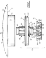
- the plug 10 illustrated in the figures essentially consists of a plug body 12 in two parts 14 and 16 and by a cover 18.
- the first part 14 of the plug body 12 which is the upper part when considering the figures, is also called the plate, while the second lower part 16 is called the bowl.
- the different components 14, 16 and 18 have a general shape of revolution around a vertical axis by considering the figures.
- the plate 14 is essentially constituted by a closure plate 20 whose lower face 22 facing the bowl 16 has a conical sealing surface 24 and an annular clearance 26 which are provided to cooperate with the upper part of a filling pipe or line 28 illustrated in FIGS. 4 and 7, as will be explained below.
- the cylindrical lateral wall of the plate 20 has a projecting external radial rib 30.
- closure plate 20 In its central part, the closure plate 20 is extended vertically downwards by an annular cylindrical attachment skirt 32.
- the external cylindrical surface 34 of the skirt 32 has a profiled internal radial groove 36 while the radial end face 38 comprises a housing which receives an O-ring seal 40.
- the radial groove 36 is delimited axially downwards by two arcuate sections of an external radial shoulder 42.
- the plate 14 also includes a cylindrical annular upper skirt 44 which extends vertically above the upper face 46 of the closure plate 20.
- the upper skirt 44 constitutes the fixed body of a lock 48, the barrel 50 of which is rotatably mounted in the skirt 44.
- the outlet rod 52 of the barrel 50 has a radial groove 54 and ends in an end portion 56 of rectangular section.
- the skirt 44 has in its thickness a vertical axial housing 58 provided for receiving the flakes 60 of the barrel 50 and thus immobilizing in rotation the barrel 50 relative to the body 44.
- the upper part of the barrel 50 has a radial collar 62, the lower face 64 of which bears on the upper annular face 66 of the skirt 44.
- a ring-shaped seal 68 is also provided at the upper part of the lock body 44.
- the cover 18 consists essentially of an upper veil 70 in the form of a dome which has a central hole 72 giving access to the upper face of the barrel 50 and which is extended axially inwards by an internal cylindrical annular skirt 74 wherein the latch body 44 is slidably received.
- the veil 70 also comprises an external cylindrical annular skirt 76 which has on its internal face, and in the vicinity of its annular end edge 78, a rib 80 which is designed to cooperate by elastic interlocking with the rib 30 of the closure plate 20 so as to ensure the connection between the cover 18 and the plate 14 when the two components are in their assembled position illustrated in particular in FIG. 2.
- the underside 22 of the closing plate 20 of the plate 14 also comprises two axial extensions which extend vertically projecting downwards 47, which are illustrated in FIG. 4, and each of which ends axially in the form of an inclined ramp 49, the ramps 49 constituting the first axial stops of the plug body 12 within the meaning of the invention.
- the second part 16 in the form of a bowl essentially consists of a flat transverse bottom 82 which is extended by a peripheral annular cylindrical skirt 84 which extends axially upwards from the upper face 86 of the bottom 82.
- the upper edge of the skirt 84 has two portions in an arc 88 of an external radial collar which constitute the second axial stops of the plug body 12 within the meaning of the invention.
- the bowl 16 also has in its center a central guide and centering core 90 which extends vertically upwards from the upper face 86 and which is intended to be received in the internal cylindrical bore 33 of the hooking skirt 32.
- the core 90 comprises a housing 92 whose cross section is complementary to the section of the rectangular profiled end 56 of the outlet member 54 of the barrel 50.
- An internal radial attachment finger 92 is formed at the upper part of the guide core 90 and it is intended to be received in elastic interlocking in the groove 54 formed in the outlet rod 52 of the barrel 50.
- the locking finger 92 may be constituted by a complete internal radial rib extending over a double turn of the core 90 or by sections of such a rib.
- the internal cylindrical wall 33 of the fastening skirt 32 has two diametrically opposite axial recesses 31.
- the bowl 16 finally comprises two hooking nozzles 94 in the form of sections of an external radial collar which are formed at the upper ends of vertical connecting arms 96 which extend upwards from the upper face 86 of the bottom 82.
- the profile of the locking spouts 94 is provided so that they are received in the groove 36 formed in the attachment skirt 32.
- the two parts 14 and 16 of the plug body 12 are assembled by elastic fitting as illustrated in FIGS. 2 and 3.
- the guide core 90 has penetrated into the bore 33 of the fastening skirt 32, the fastening fingers 92 and the fastening nozzles 94 not having still entered their respective gorges 54 and 36.
- the assembly of the two components is finished when, after having exerted an axial pressure tending to bring the two components closer, the fingers 92 and the nozzles 94 have simultaneously penetrated into the grooves 54 and 36 as illustrated in FIG. 3.
- the barrel 50 is linked in rotation with the bowl 16, this assembly being able to rotate with respect to the plate 14 if a key is introduced into the barrel 50 to return the flakes 60 which, in position locked, extend into housing 58 (see Figure 4).
- the plug 10 is provided for sealingly sealing the upper part of the pipe 28 according to the technique known as "quarter-turn locking".
- the pipe 28 includes an internal radial collar 98 which comprises two diametrically opposite housings 100 which are provided to allow the passage of the second axial locking stops 88 when the latter are brought angularly opposite the housings 100.
- the plug 10 is unlocked for opening the pipe 28 by inserting a key in the barrel 50 so as to release the barrel 50 in rotation relative to the body 44 of the lock, this release making it possible to cause rotation of the bowl 16 of a quarter turn relative to the plate 10 and to the upper end of the pipe 28 to bring the axial stops 88 again facing the housings 100.
- the invention is not limited to the mode of realization which has just been described.
- the plate 14 then comprising in its central part an indexing finger made of material which provides the same angular indexing function and d immobilization in rotation of the plate 14 relative to the bowl 16.
Landscapes
- Engineering & Computer Science (AREA)
- Life Sciences & Earth Sciences (AREA)
- Sustainable Development (AREA)
- Sustainable Energy (AREA)
- Chemical & Material Sciences (AREA)
- Combustion & Propulsion (AREA)
- Transportation (AREA)
- Mechanical Engineering (AREA)
- Closures For Containers (AREA)
- Cooling, Air Intake And Gas Exhaust, And Fuel Tank Arrangements In Propulsion Units (AREA)
Applications Claiming Priority (2)
| Application Number | Priority Date | Filing Date | Title |
|---|---|---|---|
| FR9312765 | 1993-10-26 | ||
| FR9312765A FR2711586B1 (fr) | 1993-10-26 | 1993-10-26 | Bouchon pour la fermeture de la canalisation de remplissage d'un réservoir de carburant de véhicule automobile. |
Publications (3)
| Publication Number | Publication Date |
|---|---|
| EP0650903A2 true EP0650903A2 (de) | 1995-05-03 |
| EP0650903A3 EP0650903A3 (de) | 1995-09-27 |
| EP0650903B1 EP0650903B1 (de) | 1997-06-04 |
Family
ID=9452227
Family Applications (1)
| Application Number | Title | Priority Date | Filing Date |
|---|---|---|---|
| EP94116153A Expired - Lifetime EP0650903B1 (de) | 1993-10-26 | 1994-10-13 | Tankverschlussdeckel für Kraftstoffeinfüllrohr eines Fahrzeuges |
Country Status (5)
| Country | Link |
|---|---|
| US (1) | US5667093A (de) |
| EP (1) | EP0650903B1 (de) |
| DE (1) | DE69403605T2 (de) |
| ES (1) | ES2104248T3 (de) |
| FR (1) | FR2711586B1 (de) |
Families Citing this family (6)
| Publication number | Priority date | Publication date | Assignee | Title |
|---|---|---|---|---|
| US6223923B1 (en) | 1998-02-17 | 2001-05-01 | Joseph Fishman | Lockable safety release gas cap |
| US6935527B1 (en) * | 2002-03-22 | 2005-08-30 | Richard E. Brock | Locking filler cap |
| US8991434B2 (en) | 2006-09-14 | 2015-03-31 | The Knox Company | Locking cap system |
| FR2942429B1 (fr) * | 2009-02-25 | 2011-03-25 | Itw De France | Bouchon de tubulure de remplissage |
| DE102017121953B3 (de) | 2017-09-21 | 2018-11-29 | Reutter Gmbh | Verschluss für einen Behälter |
| US11821565B2 (en) | 2020-02-03 | 2023-11-21 | Knox Associates, Inc. | Locking cap for fire department connections |
Family Cites Families (17)
| Publication number | Priority date | Publication date | Assignee | Title |
|---|---|---|---|---|
| US2696100A (en) * | 1953-03-09 | 1954-12-07 | Charles H Nehls | Cap construction |
| US2797841A (en) * | 1955-06-02 | 1957-07-02 | Robert L Kopp | Caps for gasoline or similar tanks for automobiles, trucks, or the like |
| US3164288A (en) * | 1963-01-10 | 1965-01-05 | C J Boomgaard | Closure and valve construction |
| US3402580A (en) * | 1967-06-02 | 1968-09-24 | Badger Mfg Corp | Locking gas cap |
| GB1237176A (en) * | 1969-06-05 | 1971-06-30 | Gen Motors Ltd | Closure caps |
| SE417123B (sv) * | 1974-06-27 | 1981-02-23 | Walter C Avrea | Anordning vid ett lock for tillslutning av en kylares pafyllningshals |
| US4136795A (en) * | 1975-09-05 | 1979-01-30 | Stant Manufacturing Company, Inc. | Plastic radiator cap |
| US4020970A (en) * | 1975-12-24 | 1977-05-03 | Illinois Tool Works Inc. | Rotatable closure device |
| DE2657328A1 (de) * | 1976-10-29 | 1978-05-11 | Stant Mfg Co | Absperrbarer verschluss fuer einen mit gewinde versehenen fuellstutzen |
| IT1098908B (it) * | 1978-09-25 | 1985-09-18 | Itw Fastex Italia Spa | Complesso di tappo e bocchettone per sereatoi del combustibile di autoveicoli |
| DE3005419C2 (de) * | 1980-02-14 | 1982-08-12 | Daimler-Benz Ag, 7000 Stuttgart | Renkverschlußdeckel für einen Tank |
| DE8136984U1 (de) * | 1981-12-18 | 1985-08-01 | Reutter Metallwarenfabrik GmbH, 7050 Waiblingen | Verschlußdeckel mit Bajonettlappen und Stutzen mit Bajonett-Gegenhälften, insbesondere für einen Kühlerstutzen eines Kraftfahrzeugs |
| JPS604455U (ja) * | 1983-06-22 | 1985-01-12 | 株式会社東海理化電機製作所 | 燃料タンクのキヤツプ |
| FR2585335B1 (fr) * | 1985-07-29 | 1989-12-22 | Bailly Comte Ets | Bouchon de tubulure dont le debouche est pourvu de rampes |
| US4765505A (en) * | 1986-07-22 | 1988-08-23 | Stant Inc. | Delayed actuation fuel cap |
| FR2654705B1 (fr) * | 1989-11-22 | 1992-03-06 | Vachette Sa | Bouchon de reservoir, en particulier bouchon de reservoir a carburant pour vehicule automobile. |
| US5279439A (en) * | 1992-04-27 | 1994-01-18 | Toyoda Gosei Co., Ltd. | Fuel cap for a pressured fuel tank |
-
1993
- 1993-10-26 FR FR9312765A patent/FR2711586B1/fr not_active Expired - Lifetime
-
1994
- 1994-10-13 ES ES94116153T patent/ES2104248T3/es not_active Expired - Lifetime
- 1994-10-13 DE DE69403605T patent/DE69403605T2/de not_active Expired - Lifetime
- 1994-10-13 EP EP94116153A patent/EP0650903B1/de not_active Expired - Lifetime
- 1994-10-20 US US08/326,462 patent/US5667093A/en not_active Expired - Lifetime
Also Published As
| Publication number | Publication date |
|---|---|
| EP0650903A3 (de) | 1995-09-27 |
| DE69403605D1 (de) | 1997-07-10 |
| US5667093A (en) | 1997-09-16 |
| FR2711586B1 (fr) | 1995-11-24 |
| DE69403605T2 (de) | 1997-09-18 |
| FR2711586A1 (fr) | 1995-05-05 |
| EP0650903B1 (de) | 1997-06-04 |
| ES2104248T3 (es) | 1997-10-01 |
Similar Documents
| Publication | Publication Date | Title |
|---|---|---|
| EP0374070B1 (de) | Vorrichtung zur Befestigung eines durch eine Wand zu führenden Teiles | |
| EP3527104B1 (de) | Mechanismus für einen behälter eines kosmetikprodukts, insbesondere einer stift eines lippenstift, und behälter, der einen solchen mechanismus umfasst | |
| EP0621154B1 (de) | Anordnung für den Verschluss eines Einfüllstutzens eines Kraftfahrzeugbrennstofftanks | |
| CH640476A5 (fr) | Bouchon d'un recipient comportant un col. | |
| EP0635651B1 (de) | Lageranordnung für eine rotierende Welle einer Scheibenwischeranlage | |
| EP0545813B1 (de) | Verschlussvorrichtung für den Einfüllstutzen des Brennstofftankes eines Automobiles | |
| EP0096604B1 (de) | Tankeinfüllstutzen, insbesondere für Kraftfahrzeuge | |
| EP0650903B1 (de) | Tankverschlussdeckel für Kraftstoffeinfüllrohr eines Fahrzeuges | |
| EP1042593B1 (de) | Verschlussvorrichtung für öleinfüllöffnung | |
| FR2586231A1 (fr) | Bouchon pour flacons ou analogues incorporant des moyens a serrure de securite d'ouverture | |
| EP0645274B1 (de) | Füllkopf für einen Kraftstofftank eines Fahrzeuges | |
| FR2761934A1 (fr) | Dispositif de remplissage d'un reservoir de carburant pour un vehicule automobile comportant une tete de remplissage a armature de renfort | |
| FR2625141A1 (fr) | Goulotte de remplissage de carburant equipee d'un dispositif de fermeture perfectionne commande de l'interieur du vehicule | |
| CA2422754A1 (fr) | Verseur a verrouillage ameliore et capsule munie dudit verseur | |
| EP0518717B1 (de) | Kühlerverschlussdeckel für Kraftfahrzeuge | |
| EP0731005B1 (de) | Lenkradschloss für ein Kraftfahrzeug | |
| WO2008081124A1 (fr) | Agencement démontable pour le verrouillage d'un pommeau sur la tige d'un levier de vitesses d'un véhicule automobile | |
| EP0055952B1 (de) | Deckel für einen Tank, insbesondere für den Brennstofftank von Fahrzeugen | |
| FR2821800A1 (fr) | Dispositif de remplissage de reservoir a carburant | |
| FR2528804A1 (fr) | Bouchon de remplissage a obturation automatique | |
| EP1157937B1 (de) | Abnehmbarer Verschluss für Flüssigkeitsbehälter | |
| EP0457633B1 (de) | Einrichtung für Befestigung eines Schlosses in einem Türgriff, insbesondere der Griff einer Autotür | |
| FR2759032A1 (fr) | Dispositif de remplissage d'un reservoir de carburant pour vehicule automobile comportant des moyens perfectionnes de mise a la masse electrique | |
| FR2676264A1 (fr) | Robinet pourvu d'un systeme de montage etanche faisant partie integrante du robinet. | |
| EP0688925A1 (de) | Drehriegel mit verbesserter Verbindungsvorrichtung |
Legal Events
| Date | Code | Title | Description |
|---|---|---|---|
| PUAI | Public reference made under article 153(3) epc to a published international application that has entered the european phase |
Free format text: ORIGINAL CODE: 0009012 |
|
| AK | Designated contracting states |
Kind code of ref document: A2 Designated state(s): DE ES GB IT |
|
| PUAL | Search report despatched |
Free format text: ORIGINAL CODE: 0009013 |
|
| AK | Designated contracting states |
Kind code of ref document: A3 Designated state(s): DE ES GB IT |
|
| 17P | Request for examination filed |
Effective date: 19951023 |
|
| GRAG | Despatch of communication of intention to grant |
Free format text: ORIGINAL CODE: EPIDOS AGRA |
|
| GRAH | Despatch of communication of intention to grant a patent |
Free format text: ORIGINAL CODE: EPIDOS IGRA |
|
| 17Q | First examination report despatched |
Effective date: 19961024 |
|
| GRAH | Despatch of communication of intention to grant a patent |
Free format text: ORIGINAL CODE: EPIDOS IGRA |
|
| GRAA | (expected) grant |
Free format text: ORIGINAL CODE: 0009210 |
|
| AK | Designated contracting states |
Kind code of ref document: B1 Designated state(s): DE ES GB IT |
|
| GBT | Gb: translation of ep patent filed (gb section 77(6)(a)/1977) |
Effective date: 19970606 |
|
| REF | Corresponds to: |
Ref document number: 69403605 Country of ref document: DE Date of ref document: 19970710 |
|
| REG | Reference to a national code |
Ref country code: ES Ref legal event code: FG2A Ref document number: 2104248 Country of ref document: ES Kind code of ref document: T3 |
|
| PLBE | No opposition filed within time limit |
Free format text: ORIGINAL CODE: 0009261 |
|
| STAA | Information on the status of an ep patent application or granted ep patent |
Free format text: STATUS: NO OPPOSITION FILED WITHIN TIME LIMIT |
|
| 26N | No opposition filed | ||
| REG | Reference to a national code |
Ref country code: GB Ref legal event code: IF02 |
|
| PGFP | Annual fee paid to national office [announced via postgrant information from national office to epo] |
Ref country code: ES Payment date: 20091026 Year of fee payment: 16 Ref country code: DE Payment date: 20091028 Year of fee payment: 16 |
|
| PGFP | Annual fee paid to national office [announced via postgrant information from national office to epo] |
Ref country code: IT Payment date: 20091028 Year of fee payment: 16 Ref country code: GB Payment date: 20091026 Year of fee payment: 16 |
|
| GBPC | Gb: european patent ceased through non-payment of renewal fee |
Effective date: 20101013 |
|
| REG | Reference to a national code |
Ref country code: DE Ref legal event code: R119 Ref document number: 69403605 Country of ref document: DE Effective date: 20110502 |
|
| PG25 | Lapsed in a contracting state [announced via postgrant information from national office to epo] |
Ref country code: GB Free format text: LAPSE BECAUSE OF NON-PAYMENT OF DUE FEES Effective date: 20101013 |
|
| REG | Reference to a national code |
Ref country code: ES Ref legal event code: FD2A Effective date: 20111118 |
|
| PG25 | Lapsed in a contracting state [announced via postgrant information from national office to epo] |
Ref country code: IT Free format text: LAPSE BECAUSE OF NON-PAYMENT OF DUE FEES Effective date: 20101013 |
|
| PG25 | Lapsed in a contracting state [announced via postgrant information from national office to epo] |
Ref country code: ES Free format text: LAPSE BECAUSE OF NON-PAYMENT OF DUE FEES Effective date: 20101014 |
|
| PG25 | Lapsed in a contracting state [announced via postgrant information from national office to epo] |
Ref country code: DE Free format text: LAPSE BECAUSE OF NON-PAYMENT OF DUE FEES Effective date: 20110502 |