EP0650923A1 - Reaktor zur katalytischen Entfernung von CO in H2-reichem Gas - Google Patents
Reaktor zur katalytischen Entfernung von CO in H2-reichem Gas Download PDFInfo
- Publication number
- EP0650923A1 EP0650923A1 EP94116201A EP94116201A EP0650923A1 EP 0650923 A1 EP0650923 A1 EP 0650923A1 EP 94116201 A EP94116201 A EP 94116201A EP 94116201 A EP94116201 A EP 94116201A EP 0650923 A1 EP0650923 A1 EP 0650923A1
- Authority
- EP
- European Patent Office
- Prior art keywords
- reactor
- reactor according
- oxidation catalyst
- catalyst
- al2o3
- Prior art date
- Legal status (The legal status is an assumption and is not a legal conclusion. Google has not performed a legal analysis and makes no representation as to the accuracy of the status listed.)
- Granted
Links
Images



Classifications
-
- H—ELECTRICITY
- H01—ELECTRIC ELEMENTS
- H01M—PROCESSES OR MEANS, e.g. BATTERIES, FOR THE DIRECT CONVERSION OF CHEMICAL ENERGY INTO ELECTRICAL ENERGY
- H01M8/00—Fuel cells; Manufacture thereof
- H01M8/06—Combination of fuel cells with means for production of reactants or for treatment of residues
- H01M8/0606—Combination of fuel cells with means for production of reactants or for treatment of residues with means for production of gaseous reactants
- H01M8/0612—Combination of fuel cells with means for production of reactants or for treatment of residues with means for production of gaseous reactants from carbon-containing material
- H01M8/0625—Combination of fuel cells with means for production of reactants or for treatment of residues with means for production of gaseous reactants from carbon-containing material in a modular combined reactor/fuel cell structure
- H01M8/0631—Reactor construction specially adapted for combination reactor/fuel cell
-
- B—PERFORMING OPERATIONS; TRANSPORTING
- B01—PHYSICAL OR CHEMICAL PROCESSES OR APPARATUS IN GENERAL
- B01J—CHEMICAL OR PHYSICAL PROCESSES, e.g. CATALYSIS OR COLLOID CHEMISTRY; THEIR RELEVANT APPARATUS
- B01J12/00—Chemical processes in general for reacting gaseous media with gaseous media; Apparatus specially adapted therefor
- B01J12/007—Chemical processes in general for reacting gaseous media with gaseous media; Apparatus specially adapted therefor in the presence of catalytically active bodies, e.g. porous plates
-
- B—PERFORMING OPERATIONS; TRANSPORTING
- B01—PHYSICAL OR CHEMICAL PROCESSES OR APPARATUS IN GENERAL
- B01J—CHEMICAL OR PHYSICAL PROCESSES, e.g. CATALYSIS OR COLLOID CHEMISTRY; THEIR RELEVANT APPARATUS
- B01J19/00—Chemical, physical or physico-chemical processes in general; Their relevant apparatus
- B01J19/32—Packing elements in the form of grids or built-up elements for forming a unit or module inside the apparatus for mass or heat transfer
-
- C—CHEMISTRY; METALLURGY
- C01—INORGANIC CHEMISTRY
- C01B—NON-METALLIC ELEMENTS; COMPOUNDS THEREOF; METALLOIDS OR COMPOUNDS THEREOF NOT COVERED BY SUBCLASS C01C
- C01B3/00—Hydrogen; Gaseous mixtures containing hydrogen; Separation of hydrogen from mixtures containing it; Purification of hydrogen; Reversible storage of hydrogen
- C01B3/50—Separation of hydrogen or hydrogen-containing gases from gaseous mixtures, e.g. purification
- C01B3/56—Separation of hydrogen or hydrogen-containing gases from gaseous mixtures, e.g. purification by contacting with solids; Regeneration of used solids
- C01B3/58—Separation of hydrogen or hydrogen-containing gases from gaseous mixtures, e.g. purification by contacting with solids; Regeneration of used solids including a catalytic reaction
- C01B3/583—Separation of hydrogen or hydrogen-containing gases from gaseous mixtures, e.g. purification by contacting with solids; Regeneration of used solids including a catalytic reaction the reaction being the selective oxidation of carbon monoxide
-
- H—ELECTRICITY
- H01—ELECTRIC ELEMENTS
- H01M—PROCESSES OR MEANS, e.g. BATTERIES, FOR THE DIRECT CONVERSION OF CHEMICAL ENERGY INTO ELECTRICAL ENERGY
- H01M8/00—Fuel cells; Manufacture thereof
- H01M8/06—Combination of fuel cells with means for production of reactants or for treatment of residues
- H01M8/0662—Treatment of gaseous reactants or gaseous residues, e.g. cleaning
-
- B—PERFORMING OPERATIONS; TRANSPORTING
- B01—PHYSICAL OR CHEMICAL PROCESSES OR APPARATUS IN GENERAL
- B01J—CHEMICAL OR PHYSICAL PROCESSES, e.g. CATALYSIS OR COLLOID CHEMISTRY; THEIR RELEVANT APPARATUS
- B01J2219/00—Chemical, physical or physico-chemical processes in general; Their relevant apparatus
- B01J2219/32—Details relating to packing elements in the form of grids or built-up elements for forming a unit of module inside the apparatus for mass or heat transfer
- B01J2219/322—Basic shape of the elements
- B01J2219/32203—Sheets
- B01J2219/3221—Corrugated sheets
-
- B—PERFORMING OPERATIONS; TRANSPORTING
- B01—PHYSICAL OR CHEMICAL PROCESSES OR APPARATUS IN GENERAL
- B01J—CHEMICAL OR PHYSICAL PROCESSES, e.g. CATALYSIS OR COLLOID CHEMISTRY; THEIR RELEVANT APPARATUS
- B01J2219/00—Chemical, physical or physico-chemical processes in general; Their relevant apparatus
- B01J2219/32—Details relating to packing elements in the form of grids or built-up elements for forming a unit of module inside the apparatus for mass or heat transfer
- B01J2219/322—Basic shape of the elements
- B01J2219/32203—Sheets
- B01J2219/32213—Plurality of essentially parallel sheets
-
- B—PERFORMING OPERATIONS; TRANSPORTING
- B01—PHYSICAL OR CHEMICAL PROCESSES OR APPARATUS IN GENERAL
- B01J—CHEMICAL OR PHYSICAL PROCESSES, e.g. CATALYSIS OR COLLOID CHEMISTRY; THEIR RELEVANT APPARATUS
- B01J2219/00—Chemical, physical or physico-chemical processes in general; Their relevant apparatus
- B01J2219/32—Details relating to packing elements in the form of grids or built-up elements for forming a unit of module inside the apparatus for mass or heat transfer
- B01J2219/322—Basic shape of the elements
- B01J2219/32203—Sheets
- B01J2219/32213—Plurality of essentially parallel sheets
- B01J2219/3222—Plurality of essentially parallel sheets with sheets having corrugations which intersect at an angle different from 90 degrees
-
- B—PERFORMING OPERATIONS; TRANSPORTING
- B01—PHYSICAL OR CHEMICAL PROCESSES OR APPARATUS IN GENERAL
- B01J—CHEMICAL OR PHYSICAL PROCESSES, e.g. CATALYSIS OR COLLOID CHEMISTRY; THEIR RELEVANT APPARATUS
- B01J2219/00—Chemical, physical or physico-chemical processes in general; Their relevant apparatus
- B01J2219/32—Details relating to packing elements in the form of grids or built-up elements for forming a unit of module inside the apparatus for mass or heat transfer
- B01J2219/324—Composition or microstructure of the elements
- B01J2219/32408—Metal
-
- B—PERFORMING OPERATIONS; TRANSPORTING
- B01—PHYSICAL OR CHEMICAL PROCESSES OR APPARATUS IN GENERAL
- B01J—CHEMICAL OR PHYSICAL PROCESSES, e.g. CATALYSIS OR COLLOID CHEMISTRY; THEIR RELEVANT APPARATUS
- B01J2219/00—Chemical, physical or physico-chemical processes in general; Their relevant apparatus
- B01J2219/32—Details relating to packing elements in the form of grids or built-up elements for forming a unit of module inside the apparatus for mass or heat transfer
- B01J2219/324—Composition or microstructure of the elements
- B01J2219/32425—Ceramic
-
- B—PERFORMING OPERATIONS; TRANSPORTING
- B01—PHYSICAL OR CHEMICAL PROCESSES OR APPARATUS IN GENERAL
- B01J—CHEMICAL OR PHYSICAL PROCESSES, e.g. CATALYSIS OR COLLOID CHEMISTRY; THEIR RELEVANT APPARATUS
- B01J2219/00—Chemical, physical or physico-chemical processes in general; Their relevant apparatus
- B01J2219/32—Details relating to packing elements in the form of grids or built-up elements for forming a unit of module inside the apparatus for mass or heat transfer
- B01J2219/324—Composition or microstructure of the elements
- B01J2219/32466—Composition or microstructure of the elements comprising catalytically active material
-
- C—CHEMISTRY; METALLURGY
- C01—INORGANIC CHEMISTRY
- C01B—NON-METALLIC ELEMENTS; COMPOUNDS THEREOF; METALLOIDS OR COMPOUNDS THEREOF NOT COVERED BY SUBCLASS C01C
- C01B2203/00—Integrated processes for the production of hydrogen or synthesis gas
- C01B2203/04—Integrated processes for the production of hydrogen or synthesis gas containing a purification step for the hydrogen or the synthesis gas
- C01B2203/0435—Catalytic purification
- C01B2203/044—Selective oxidation of carbon monoxide
-
- C—CHEMISTRY; METALLURGY
- C01—INORGANIC CHEMISTRY
- C01B—NON-METALLIC ELEMENTS; COMPOUNDS THEREOF; METALLOIDS OR COMPOUNDS THEREOF NOT COVERED BY SUBCLASS C01C
- C01B2203/00—Integrated processes for the production of hydrogen or synthesis gas
- C01B2203/04—Integrated processes for the production of hydrogen or synthesis gas containing a purification step for the hydrogen or the synthesis gas
- C01B2203/0465—Composition of the impurity
- C01B2203/047—Composition of the impurity the impurity being carbon monoxide
-
- Y—GENERAL TAGGING OF NEW TECHNOLOGICAL DEVELOPMENTS; GENERAL TAGGING OF CROSS-SECTIONAL TECHNOLOGIES SPANNING OVER SEVERAL SECTIONS OF THE IPC; TECHNICAL SUBJECTS COVERED BY FORMER USPC CROSS-REFERENCE ART COLLECTIONS [XRACs] AND DIGESTS
- Y02—TECHNOLOGIES OR APPLICATIONS FOR MITIGATION OR ADAPTATION AGAINST CLIMATE CHANGE
- Y02E—REDUCTION OF GREENHOUSE GAS [GHG] EMISSIONS, RELATED TO ENERGY GENERATION, TRANSMISSION OR DISTRIBUTION
- Y02E60/00—Enabling technologies; Technologies with a potential or indirect contribution to GHG emissions mitigation
- Y02E60/30—Hydrogen technology
- Y02E60/50—Fuel cells
Definitions
- the invention relates to a reactor for the selective catalytic removal of CO in H2-rich gas.
- a reactor for the selective catalytic removal of CO in H2-rich gas.
- Such a reactor is used e.g. for the CO removal from the exhaust gas of a reformer in order to process the exhaust gas as a reactant for a fuel cell.
- the catalytic oxidation of CO in an H2-rich atmosphere is mainly carried out in technology in fixed bed reactors on selective precious metal contacts by injecting oxygen or air.
- the catalyst is in the form of pellets or balls as a bed in the reaction tube.
- the object of the invention is therefore to create a reactor with which an increased selectivity of the CO oxidation is achieved and at the same time steep temperature gradients in the reactor are avoided.
- the reactor comprises a structure which, through its shape and structure, generates a turbulent flow and promotes heat transfer.
- the precious metal-containing selective CO oxidation catalyst is applied to this structure. Mass and heat transfer resistances, as they occur in a fixed bed reactor, are reduced by the turbulent flow generated in the structure under certain reaction conditions. As a result, higher CO conversions and uniform temperature profiles can be achieved in the reactor. In addition, the dynamic behavior of the reactor to changes in operating conditions is significantly improved.
- This structure can be a — in particular three-dimensional — support structure that is introduced into the reactor, for example a metallic or ceramic cross-channel structure.
- metallic or ceramic sponge or fiber structures can also serve as catalyst supports. The porosity of such structures must be selected so that the maximum permissible pressure drop is not exceeded.
- the reactor according to the invention is particularly suitable for use under non-stationary conditions, such as those prevailing when fuel cells are used in passenger and commercial vehicles.
- they can also be used for power generators that use fuel cells.
- the selective oxidation on the CO oxidation catalyst takes place after the following reaction: CO + 0.5 O2 ---> CO2.
- the following selective CO oxidation catalysts containing precious metals are advantageously used:
- Pt / Al2O3 in particular: Pt (0.3 ma%) / Al2O3
- Pt zeolite especially Pt (1ma%) NaY.
- Cross-channel structures consist of corrugated, serrated or similarly shaped metal foils or layers, which are superimposed.
- the areas of the "wave bellies" on both sides of the films or layers serve as flow channels.
- the individual layers are placed on top of one another in such a way that the flow channels of adjacent layers form an angle enclose between 0 ° and 90 °, preferably 90 °.
- the flow channels should continue to make an angle between 0 ° and 90 °, preferably 45 °, to the longitudinal axis of the reactor.
- the Pt / Al2O3 catalyst Based on the Pt / Al2O3 catalyst, the application of the catalyst to the metal honeycomb body with cross-channel structure is described below.
- the Pt (5 ma -%) / Al2O3 used is an impregnation catalyst in the form of powder, which is commercially available.
- the platinum is elementary on the aluminum oxide, which serves as a carrier material.
- the powder When delivered, the powder has an average grain size of approx. 60 ⁇ m, which is reduced to 3 ⁇ m by a grinding process (see below).
- the BET surface area of the catalyst is approximately 140 m2 / g.
- the cross-channel support is preheated for several hours in an air atmosphere in such a way that the resulting structure of the support surface is adapted to the dimension of the catalyst powder.
- the Pt (5 ma%) / Al2O3 catalyst powder is ground in aqueous suspension before the coating process. Binder is then added to the suspension and made up with water so that a defined solid concentration is present.
- the pretreated metal support is then immersed in the catalyst suspension. After the dipping process, the channels of the carrier are blown free and the carrier is dried. The dipping process with subsequent drying is repeated until the required application mass is reached. Finally, the coated metal support is calcined.
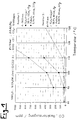
- Fig. 1 shows an example of a comparison of the CO output concentrations (ordinate) achieved in the temperature range from 80 o C to 130 o C (abscissa) in a fixed bed reactor (circular measuring points) and on metal supports with a cross-channel structure (measuring points as a cross or square) for different ones Reactor diameter.
- the layer height of the cross-channel structure was 3.0 mm.
- Pt / Al2O3 in various Pt concentrations was used as the catalyst.
- the CO input concentration was 10,000 ppm in each case.
- the input gas had: 10% H2O, 1% CH3OH, rest H2 / CO2 in a ratio of 3: 1.
- the results shown show that for a given reactor diameter, lower CO starting concentrations are achieved than in the fixed bed reactor by using the metal supports.
- the CO concentration in the temperature range mentioned can be reduced from 10,000 ppm to below 40 ppm.
- FIG. 2 shows the process diagram of selective CO oxidation with the reactor according to the invention.
- the exhaust gas from a CH3OH reformer which can contain up to 1 vol .-% CO
- the metal honeycomb bodies with a cross-channel structure are located in the reactor, which are coated with the precious metal-containing selective catalyst.
- the CO is oxidized to CO2 on the catalyst.
- the CO concentration of the gas emerging from the reactor is less than 40 ppm.
- FIG. 3 shows an example of a cross channel carrier.
- Three are shown jagged or corrugated metal foils L.
- the indented volume areas left and right of a sheet L each form flow channels K.
- the individual layers are so superposed that the flow channels include a certain angle between 0 o and 90 ° with one another. In the drawing, this angle is approximately 90 ° .
- the individual sheets are drawn at a distance from one another, but in fact they lie directly on top of one another.
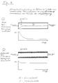
- Fig. 4 shows the formation of the boundary film in a gas-flow tube with a smooth inner tube wall compared to a tube with a structured inner tube wall.
- a smooth inner tube wall a thick boundary film is formed, which results in a greatly reduced mass transfer to the catalytically coated reactor wall.
- the boundary film remains uniformly thin over the entire length of the reactor due to the flow turbulence generated on the wall and thus causes a good mass transfer.
- the Sherwood numbers plotted for both cases, which serve as a measure of the mass transfer, illustrate the different mass transfer properties of both reactors.
- FIG. 5 shows an example of a reactor with a structured inner tube wall on which a catalytic coating is applied.
- the corrugated structure of the wall prevents the formation of a thick border film and thereby increases the mass transfer to the catalytically active layer.
Landscapes
- Chemical & Material Sciences (AREA)
- Chemical Kinetics & Catalysis (AREA)
- Organic Chemistry (AREA)
- Engineering & Computer Science (AREA)
- General Chemical & Material Sciences (AREA)
- Sustainable Energy (AREA)
- Sustainable Development (AREA)
- Electrochemistry (AREA)
- Life Sciences & Earth Sciences (AREA)
- Manufacturing & Machinery (AREA)
- Combustion & Propulsion (AREA)
- Inorganic Chemistry (AREA)
- Physics & Mathematics (AREA)
- Thermal Sciences (AREA)
- Catalysts (AREA)
- Physical Or Chemical Processes And Apparatus (AREA)
Abstract
Description
- Die Erfindung betrifft einen Reaktor zur selektiven katalytischen Entfernung von CO in H₂-reichem Gas. Anwendung findet ein solcher Reaktor z.B. für die CO-Entfernung aus dem Abgas eines Reformers, um das Abgas als Reaktionsstoff für eine Brennstoffzelle aufzubereiten.
- Die katalytische Oxidation von CO in H₂-reicher Atmosphäre wird in der Technik überwiegend in Festbettreaktoren an selektiven Edelmetallkontakten durch Eindüsen von Sauerstoff oder Luft durchgeführt. Der Katalysator liegt dabei in Form von Pellets oder Kugeln als Schüttung im Reaktionsrohr vor. Die von der Anmelderin durchgeführten Untersuchungen über die Anwendbarkeit der selektiven CO-Oxidation zur CO-Entfernung aus dem Abgas des CH₃OH-Reformers zeigen, daß die auftretenden Stoff- und Wärmetransportwiderstände zu einer verminderten Selektivität der CO-Oxidation und zu steilen Temperaturgradienten im Reaktor führen. Insgesamt bedeutet dies eine Absenkung der für die Brennstoffzelle zur Verfügung stehenden H₂-Menge und eine Erhöhung des CO-Niveaus an der Elektrode.
- Aufgabe der Erfindung ist es deshalb, einen Reaktor zu schaffen, mit dem eine erhöhte Selektivität der CO-Oxidation erreicht und gleichzeitig steile Temperaturgradienten im Reaktor vermieden werden.
- Diese Aufgabe wird durch den Reaktor nach dem Patentanspruch 1 gelöst.
- Erfindungsgemäß umfaßt der Reaktor eine Struktur, die durch Form und Aufbau eine turbulente Strömung erzeugt und den Wärmetransport begünstigt. Der edelmetallhaltige selektive CO-Oxidationskatalysator ist auf diese Struktur aufgebracht.
Stoff- und Wärmetransportwiderstände, wie sie in einem Festbettreaktor auftreten, werden durch die in der Struktur unter bestimmten Reaktionsbedingungen erzeugte turbulente Strömung abgebaut. Dadurch können höhere CO-Umsätze und einheitliche Temperaturverlaufe im Reaktor erzielt werden. Darüberhinaus wird das dynamische Verhalten des Reaktors auf Änderungen der Betriebsbedingungen wesentlich verbessert.
Diese Struktur kann eine - insbesondere dreidimensionale - Trägerstruktur sein, die in den Reaktor eingebracht wird, z.B. eine metallische oder keramische Kreuzkanalstruktur. Möglich ist aber auch, die Reaktorwand selbst als turbulenzerzeugende und wärmetransportbegünstigende Struktur auszubilden. Ebenso können auch metallische oder keramische Schwamm- oder Faserstrukturen als Katalysatorträger dienen. Dabei muß die Porosität derartiger Strukturen so gewählt sein, daß der maximal zulässige Druckabfall nicht überschritten wird. - Der erfindungsgemäße Reaktor eignet sich insbesondere zur Anwendung unter nicht-stationären Bedingungen, wie sie beim Einsatz von Brennstoffzellen in Personen- und Nutzfahrzeugen vorherrschen. Sie können z.B. auch für Stromerzeugungsaggregate, bei denen Brennstoffzellen verwendet werden, genutzt werden.
- Die selektive Oxidation an dem CO-Oxidationskatalysator läuft nach folgender Reaktion ab:
CO + 0,5 O₂ ---> CO₂.
Abhängig von der Arbeitstemperaturen werden vorteilhaft die folgenden edelmetallhaltigen, selektiven CO-Oxidationskatalysatoren verwendet: - Pt/Al₂O₃, Ru/Al₂O₃
- insbesondere:
- Pt(x ma-%)/Al₂O₃ mit 1 ≦ x ≦ 7
Pt(5 ma-%)/Al₂O₃
Ru(0.44 ma-%)/Al₂O₃ - Pt/Al₂O₃, insbesondere: Pt(0,3 ma-%)/Al₂O₃
- Pt-Zeolith, insbesondere Pt(1ma-%)NaY.
- Die an sich bekannten Wärme- und Stofftransporteigenschaften metallischer Kreuzkanalstrukturen (siehe z.B. Firmenprospekt der Firma Sulzer) werden mit den selektiven Eigenschaften des edelmetallhaltigen Oxidationskatalysators kombiniert.
Kreuzkanalstrukturen bestehen aus gewelltem, gezackten oder in ähnlicher Weise geformten Metallfolien oder -schichten, die übereinandergelegt werden. Die Bereiche der "Wellenbäuche" beiderseits der Folien oder Schichten dienen dabei als Strömungskanäle. Die einzelnen Lagen werden derart aufeinandergelegt, daß die Strömungskanäle benachbarter Lagen einen Winkel zwischen 0° und 90°, vorzugsweise 90°, zueinander einschließen. Die Strömungskanäle sollten weiterhin zur Reaktorlängsachse einen Winkel zwischen 0° und 90°, vorzugsweise 45°, einnehmen. - Anhand des Pt/Al₂O₃-Katalysators wird im folgenden die Aufbringung des Katalysators auf den Metallwabenkörper mit Kreuzkanalstruktur beschrieben. Bei dem eingesetzten Pt(5 ma-%)/Al₂O₃ handelt es sich um einen Tränkkatalysator in Form von Pulver, das kommerziell erhältlich ist. Das Platin liegt elementar auf dem Aluminiumoxid, das als Trägermaterial dient, vor. Das Pulver hat im Anlieferungszustand eine mittlere Korngröße von ca. 60 µm, die durch einen Mahlvorgang (s.u.) auf 3 µm herabgesetzt wird. Die BET-Oberfläche des Katalysators beträgt ca. 140 m²/g.
Der Kreuzkanalträger wird zur Vorbehandlung mehrere Stunden unter Luftatmosphäre in einer Weise geglüht, daß die entstehende Struktur der Trägeroberfläche an die Dimension des Katalysatorpulvers angepaßt ist. Das Pt(5 ma-%)/Al₂O₃-Katalysatorpulver wird vor dem Beschichtungsvorgang in wäßriger Suspension gemahlen. Anschließend wird der Suspension Bindemittel zugegeben und mit Wasser aufgefüllt, so daß eine definierte Feststoffkonzentration vorliegt. Der vorbehandelte Metallträger wird dann in die Katalysatorsuspension getaucht. Nach dem Tauchvorgang werden die Kanäle des Trägers freigeblasen und der Träger getrocknet. Der Tauchvorgang mit anschließender Trocknung wird sooft wiederholt, bis die erforderliche Auftragsmasse erreicht ist. Abschließend wird der beschichtete Metallträger kalziniert. - Die Erfindung wird im folgenden mit Hilfe von Fig. näher erläutert.
Es zeigen: - Fig. 1
- ein Diagramm zu den experimentell erreichten CO-Ausgangskonzentrationen;
- Fig. 2
- eine schematische Darstellung des erfindungsgemäßen Reaktors;
- Fig. 3
- ein Metallwabenkörper mit Kreuzkanalstruktur;
- Fig. 4
- Ausbildung des Grenzfilms in gasdurchströmten Rohren mit glatter und strukturierter Rohrinnenwand;
- Fig. 5
- Reaktor mit strukturierter Rohrinnenwand.
- Fig. 1 zeigt beispielhaft einen Vergleich der erzielten CO-Ausgangskonzentrationen (Ordinate) im Temperaturbereich von 80 oC bis 130oC (Abszisse) in einem Festbettreaktor (kreisförmige Meßpunkte) und auf Metallträgern mit Kreuzkanalstruktur (Meßpunkte als Kreuz oder Quadrat) für jeweils unterschiedliche Reaktordurchmesser. Die Lagenhöhe der Kreuzkanalstruktur betrug 3.0 mm. Als Katalysator wurde Pt/Al₂O₃ in verschiedenen Pt-Konzentrationen verwendet. Die CO-Eingangskonzentration betrug jeweils 10 000 ppm. Das Eingangsgas wies neben dem CO und der Luftfolgende Zusammensetzung auf: 10% H₂O, 1% CH₃OH, Rest H₂/CO₂ im Verhältnis 3:1.
Die dargestellten Ergebnisse zeigen, daß bei gegebenem Reaktordurchmesser durch Verwendung der Metallträger niedrigere CO-Ausgangskonzentrationen als im Festbettreaktor erzielt werden. Beispielsweise kann bei Einsatz der bezeichneten Metallträger in einem Reaktor mit einem Durchmesser von 19 mm die CO-Konzentration im genannten Temperaturbereich von 10 000 ppm auf unter 40 ppm gesenkt werden. - In Fig. 2 ist das Verfahrensschema der selektiven CO-Oxidation mit dem erfindungsgemäßen Reaktor dargestellt. In diesem Beispiel wird dem Reaktor das Abgas aus einem CH₃OH-Reformer, das bis zu 1 Vol.-% CO enthalten kann, zugeführt. In dem Reaktor befinden sich die Metallwabenkörper mit Kreuzkanalstruktur, die mit dem edelmetallhaltigen selektiven Katalysator beschichtet sind. An dem Katalysator wird das CO zu CO₂ oxidiert. Die CO-Konzentration des aus dem Reaktor austretenden Gases beträgt weniger als 40 ppm.
- Fig. 3 zeigt ein Beispiel für einen Kreuzkanalträger. Dargestellt sind drei gezackte bzw. gewellte Metallfolien L. Die eingebuchteten Volumenbereiche links und rechts einer Folie L bilden jeweils Strömungskanäle K. Die einzelnen Lagen werden derart übereinander angeordnet, daß die Strömungskanäle einen bestimmten Winkel zwischen 0o und 90° miteinander einschließen. In der Zeichnung beträgt dieser Winkel etwa 90o. Zur Erhöhung der Übersichtlichkeit sind die einzelnen Bleche beabstandet voneinander gezeichnet, tatsächlich liegen sie jedoch unmittelbar aufeinander.
- Fig. 4 zeigt die Ausbildung des Grenzfilms in einem gasdurchströmten Rohr mit glatter Rohrinnenwand im Vergleich zu einem Rohr mit strukturierter Rohrinnenwand. Im Fall der glatten Rohrinnenwand bildet sich ein dicker Grenzfilm aus, der einen stark verminderten Stofftransport an die katalytisch beschichtete Reaktorwand zur Folge hat. Bei strukturierter Rohrwand bleibt der Grenzfilm durch die an der Wand erzeugte Strömungsturbulenz über die gesamte Länge des Reaktors gleichmäßig dünn und bewirkt somit einen guten Stoffübergang. Die für beide Fälle aufgetragenen Sherwoodzahlen, die als Maß für den Stoffübergang dienen, verdeutlichen die unterschiedlichen Stoffübergangseigenschaften beider Reaktoren.
- Fig. 5 zeigt beispielhaft einen Reaktor mit strukturierter Rohrinnenwand, auf der eine katalytische Beschichtung aufgebracht ist. Die gewellte Struktur der Wand verhindert die Ausbildung eines dicken Grenzfilms und erhöht dadurch den Stoffübergang an die katalytisch aktive Schicht.
Claims (10)
- Reaktor zur katalytischen Entfernung von CO in H₂-reichem Gas mit einem edelmetallhaltigen selektiven CO-Oxidationskatalysator, dadurch gekennzeichnet, daß der Reaktor eine Struktur umfaßt, die eine turbulente Strömung erzeugt und den Wärmetransport begünstigt, wobei die Struktur mit dem CO-Oxidationskatalysator beschichtet ist.
- Reaktor nach Anspruch 1, dadurch gekennzeichnet, daß die Struktur ein metallischer oder keramischer Träger mit Kreuzkanalstruktur ist.
- Reaktor nach einem der vorangehenden Ansprüche, dadurch gekennzeichnet, daß die Struktur ein metallischer oder keramischer Träger mit Schwamm- oder Faserstruktur ist.
- Reaktor nach einem der vorangehenden Ansprüche, dadurch gekennzeichnet, daß die Struktur durch die Reaktorwand gebildet ist.
- Reaktor nach einem der Ansprüche 2 bis 4, dadurch gekennzeichnet, daß die Oberflächenstruktur des metallischen oder keramischen Trägers oder der Reaktorwand an die Dimension des Katalysatorpulvers angepaßt ist.
- Reaktor nach einem der vorangehenden Ansprüche, dadurch gekennzeichnet, daß die Schichtdicke des CO-Oxidationskatalysators an die CO-Eingangskonzentration angepaßt ist.
- Reaktor nach einem der vorangehenden Ansprüche, dadurch gekennzeichnet, daß der CO-Oxidationskatalysator Pt/Al₂O₃ ist.
- Reaktor nach Anspruch 7, dadurch gekennzeichnet, daß die Pt-Cluster des Katalysator-Pulvers eine Größe im Bereich von 3 bis 10 nm aufweisen.
- Reaktor nach einem der vorangehenden Ansprüche, dadurch gekennzeichnet, daß der CO-Oxidationskatalysator Ru/Al₂O₃ oder Pt-Zeolith ist.
- Verwendung des Reaktors in Verbindung mit einer Brennstoffzelle, insbesondere für mobile Anwendungen.
Applications Claiming Priority (2)
| Application Number | Priority Date | Filing Date | Title |
|---|---|---|---|
| DE4334981 | 1993-10-14 | ||
| DE4334981A DE4334981C2 (de) | 1993-10-14 | 1993-10-14 | Verwendung eines Reaktors zur katalytischen Entfernung von CO in H¶2¶-reichem Gas |
Publications (2)
| Publication Number | Publication Date |
|---|---|
| EP0650923A1 true EP0650923A1 (de) | 1995-05-03 |
| EP0650923B1 EP0650923B1 (de) | 1997-02-05 |
Family
ID=6500105
Family Applications (1)
| Application Number | Title | Priority Date | Filing Date |
|---|---|---|---|
| EP94116201A Expired - Lifetime EP0650923B1 (de) | 1993-10-14 | 1994-10-12 | Reaktor zur katalytischen Entfernung von CO in H2-reichem Gas |
Country Status (3)
| Country | Link |
|---|---|
| US (1) | US5674460A (de) |
| EP (1) | EP0650923B1 (de) |
| DE (1) | DE4334981C2 (de) |
Cited By (4)
| Publication number | Priority date | Publication date | Assignee | Title |
|---|---|---|---|---|
| EP0743694A1 (de) * | 1995-05-15 | 1996-11-20 | Toyota Jidosha Kabushiki Kaisha | Vorrichtung zur Verminderung der Kohlenstoffmonoxydkonzentration, Vorrichtung zur Verminderung der Methanolkonzentration, und diese Vorrichtungen verwendede Brennstoffreformierungsanlage |
| WO1997025752A1 (en) * | 1996-01-11 | 1997-07-17 | International Fuel Cells Corporation | Compact selective oxidizer assemblage for fuel cell power plant |
| EP0787679A1 (de) | 1996-01-30 | 1997-08-06 | Daimler-Benz Aktiengesellschaft | Verfahren und Vorrichtung zur Gewinnung eines wasserstoffreichen, kohlenmonoxidarmen Gases |
| EP0906890A1 (de) * | 1997-10-02 | 1999-04-07 | dbb fuel cell engines GmbH | Vorrichtung zur Wasserstofferzeugung,Vorrichtung zur Kohlenmonoxid-Verringerung,Vorrichtung zur Kohlenmonoxid-Oxidation,Vorrichtung zum katalytischen Verbrennen und Verfahren zur Herstellung eines Katalysators |
Families Citing this family (23)
| Publication number | Priority date | Publication date | Assignee | Title |
|---|---|---|---|---|
| JP3519828B2 (ja) * | 1995-08-30 | 2004-04-19 | 本田技研工業株式会社 | 燃料電池システム |
| DE19544895C1 (de) * | 1995-12-01 | 1997-02-27 | Daimler Benz Ag | Verfahren und Vorrichtung zur selektiven katalytischen Oxidation von Kohlenmonoxid |
| WO1997027385A1 (fr) * | 1996-01-22 | 1997-07-31 | Institut Français Du Petrole | Precipitateur pour combustion a l'echappement de moteurs diesel ou essence, et procede associe |
| DE19606286C1 (de) * | 1996-02-21 | 1997-10-02 | Daimler Benz Ag | Verwendung eines Pt-Zeolith-Katalysatormaterials |
| DE19615562C1 (de) * | 1996-04-19 | 1997-10-09 | Zsw | Vorrichtung und Verfahren zur kombinierten Reinigung und Kompression von CO-haltigem Wasserstoff sowie Verwendung des mit dem Verfahren erhaltenen Wasserstoffs als Brenngas in Brennstoffzellen |
| BE1011581A3 (fr) * | 1997-12-01 | 1999-11-09 | Solvay | Catalyseur a base de zeolite, son utilisation et procede d'epoxydation en presence de ce catalyseur. |
| GB9826222D0 (en) * | 1998-12-01 | 1999-01-20 | Johnson Matthey Plc | Improved reactor |
| JP3604941B2 (ja) * | 1999-02-19 | 2004-12-22 | 三洋電機株式会社 | Co除去装置 |
| US6559094B1 (en) | 1999-09-09 | 2003-05-06 | Engelhard Corporation | Method for preparation of catalytic material for selective oxidation and catalyst members thereof |
| JP3715482B2 (ja) | 1999-11-04 | 2005-11-09 | エヌ・イーケムキャット株式会社 | 水素含有ガス中の一酸化炭素選択酸化触媒並びに該触媒を用いた一酸化炭素除去方法及び固体高分子電解質型燃料電池システム |
| SI20471A (sl) * | 2000-02-16 | 2001-08-31 | Kemijski in�titut | Postopek za katalitično, selektivno oksidacijo ogljikovega monoksida v plinskih mešanicah, ki vsebujejo prebitni vodik, katalizator in postopek za njegovo pripravo |
| CA2405932A1 (en) * | 2000-04-14 | 2001-11-01 | Shell Internationale Research Maatschappij B.V. | Process for the selective oxidation of carbon monoxide |
| DE10030938B4 (de) * | 2000-06-24 | 2008-02-28 | Robert Bosch Gmbh | Reaktoreinheit einer Brennstoffzellenanlage zur CO-Umformung |
| US20030162848A1 (en) * | 2000-07-25 | 2003-08-28 | Gimpel Frederik Willem Hendrik | Reactor comprising a packed bed of supported catalyst or supported catalyst precursor, and a use of the reactor |
| US20030086852A1 (en) * | 2001-10-15 | 2003-05-08 | Ballard Generation Systems Inc. | Apparatus for the selective oxidation of carbon monoxide in a hydrogen-containing gas mixture |
| US20040038801A1 (en) * | 2001-10-16 | 2004-02-26 | Hiroto Kikuchi | Catalyst using metal carrier and manufacturing method thereof |
| JP2003190801A (ja) * | 2001-10-16 | 2003-07-08 | Nissan Motor Co Ltd | 触媒およびその製造方法 |
| US7118717B2 (en) * | 2002-09-06 | 2006-10-10 | Engelhard Corporation | Simplified article for carbon monoxide removal |
| US20050096211A1 (en) * | 2003-10-31 | 2005-05-05 | Hiroshi Takeda | Catalyst for the conversion of carbon monoxide |
| US20050096212A1 (en) * | 2003-10-31 | 2005-05-05 | Hiroshi Takeda | Catalyst for the conversion of carbon monoxide |
| US8080224B2 (en) * | 2006-05-05 | 2011-12-20 | Sud-Chemie Inc. | Catalyst for the conversion of carbon monoxide |
| WO2009068510A2 (en) | 2007-11-27 | 2009-06-04 | Shell Internationale Research Maatschappij B.V. | Catalyst support |
| US7998899B2 (en) | 2007-11-27 | 2011-08-16 | Shell Oil Company | Catalyst with support structure |
Citations (1)
| Publication number | Priority date | Publication date | Assignee | Title |
|---|---|---|---|---|
| EP0432364A1 (de) * | 1989-11-30 | 1991-06-19 | Uhde GmbH | Reaktor zur Durchführung katalytischer Gasreaktionen bzw. physikalischer Trennoperationen |
Family Cites Families (12)
| Publication number | Priority date | Publication date | Assignee | Title |
|---|---|---|---|---|
| US3631073A (en) * | 1969-04-04 | 1971-12-28 | Engelhard Min & Chem | Process for oxidation of carbon monoxide |
| US4028275A (en) * | 1973-01-24 | 1977-06-07 | Mitsui Mining & Smelting Co., Ltd. | Process for preparing catalytic materials for purifying exhaust gas and catalytic materials prepared thereby |
| US4072471A (en) * | 1974-05-28 | 1978-02-07 | Mobil Oil Corporation | Catalytic converter for removing noxious components from a gaseous stream |
| GB1603107A (en) * | 1977-09-06 | 1981-11-18 | Lodge Cottrell Ltd | Gas treatment |
| US4753780A (en) * | 1983-09-26 | 1988-06-28 | Phillips Petroleum Company | Atomizing feed for cracking unit |
| EP0201614B1 (de) * | 1985-05-14 | 1989-12-27 | GebràDer Sulzer Aktiengesellschaft | Reaktor zum Durchführen von heterogenen, katalysierten chemischen Reaktionen |
| US4971768A (en) * | 1987-11-23 | 1990-11-20 | United Technologies Corporation | Diffuser with convoluted vortex generator |
| US5110560A (en) * | 1987-11-23 | 1992-05-05 | United Technologies Corporation | Convoluted diffuser |
| US4910099A (en) * | 1988-12-05 | 1990-03-20 | The United States Of America As Represented By The United States Department Of Energy | Preventing CO poisoning in fuel cells |
| JP3096302B2 (ja) * | 1989-12-11 | 2000-10-10 | ゲブリユーダー ズルツアー アクチエンゲゼルシヤフト | 不均一反応型の反応器及び反応器用触媒 |
| US5248485A (en) * | 1990-04-04 | 1993-09-28 | Outokumpu Oy | Method for mixing liquid, solids and gas and for simultaneously separating gas or gas and solids from the liquid |
| DE69321093T2 (de) * | 1993-01-08 | 1999-02-25 | Ford-Werke Ag, 50735 Koeln | Zweistufiges katalysator System für einem Verbrennungsmotor |
-
1993
- 1993-10-14 DE DE4334981A patent/DE4334981C2/de not_active Expired - Fee Related
-
1994
- 1994-10-12 EP EP94116201A patent/EP0650923B1/de not_active Expired - Lifetime
- 1994-10-14 US US08/323,216 patent/US5674460A/en not_active Expired - Lifetime
Patent Citations (1)
| Publication number | Priority date | Publication date | Assignee | Title |
|---|---|---|---|---|
| EP0432364A1 (de) * | 1989-11-30 | 1991-06-19 | Uhde GmbH | Reaktor zur Durchführung katalytischer Gasreaktionen bzw. physikalischer Trennoperationen |
Cited By (10)
| Publication number | Priority date | Publication date | Assignee | Title |
|---|---|---|---|---|
| EP0743694A1 (de) * | 1995-05-15 | 1996-11-20 | Toyota Jidosha Kabushiki Kaisha | Vorrichtung zur Verminderung der Kohlenstoffmonoxydkonzentration, Vorrichtung zur Verminderung der Methanolkonzentration, und diese Vorrichtungen verwendede Brennstoffreformierungsanlage |
| US5843195A (en) * | 1995-05-15 | 1998-12-01 | Toyota Jidosha Kabushiki Kaisha | Apparatus for reducing carbon monoxide concentration, apparatus for reducing methanol concentration, and fuel reformer utilizing the same |
| WO1997025752A1 (en) * | 1996-01-11 | 1997-07-17 | International Fuel Cells Corporation | Compact selective oxidizer assemblage for fuel cell power plant |
| US5853674A (en) * | 1996-01-11 | 1998-12-29 | International Fuel Cells, Llc | Compact selective oxidizer assemblage for fuel cell power plant |
| EP0787679A1 (de) | 1996-01-30 | 1997-08-06 | Daimler-Benz Aktiengesellschaft | Verfahren und Vorrichtung zur Gewinnung eines wasserstoffreichen, kohlenmonoxidarmen Gases |
| DE19603222C1 (de) * | 1996-01-30 | 1997-08-28 | Daimler Benz Ag | Verfahren und Vorrichtung zur Gewinnung eines wasserstoffreichen, kohlenmonoxidarmen Gases |
| US5904913A (en) * | 1996-01-30 | 1999-05-18 | Daimler-Benz Ag | Process for obtaining a high-hydrogen, low-carbon-monoxide gas |
| EP0906890A1 (de) * | 1997-10-02 | 1999-04-07 | dbb fuel cell engines GmbH | Vorrichtung zur Wasserstofferzeugung,Vorrichtung zur Kohlenmonoxid-Verringerung,Vorrichtung zur Kohlenmonoxid-Oxidation,Vorrichtung zum katalytischen Verbrennen und Verfahren zur Herstellung eines Katalysators |
| WO1999017867A3 (de) * | 1997-10-02 | 1999-08-19 | Dbb Fuel Cell Engines Ges Mit | Vorrichtung zur durchführung einer heterogen katalysierten reaktion und verfahren zur herstellung eines katalysators |
| US6517805B1 (en) | 1997-10-02 | 2003-02-11 | Ballard Power Systems Ag | Method and apparatus for producing hydrogen |
Also Published As
| Publication number | Publication date |
|---|---|
| DE4334981A1 (de) | 1995-04-20 |
| DE4334981C2 (de) | 1998-02-26 |
| US5674460A (en) | 1997-10-07 |
| EP0650923B1 (de) | 1997-02-05 |
Similar Documents
| Publication | Publication Date | Title |
|---|---|---|
| EP0650923B1 (de) | Reaktor zur katalytischen Entfernung von CO in H2-reichem Gas | |
| DE60037205T2 (de) | Katalytische vorrichtungen | |
| DE69913037T2 (de) | Reformierungsreaktor | |
| EP0556554B1 (de) | Beschichtungsdispersion für Abgaskatalysatoren | |
| DE69908242T2 (de) | Reformer | |
| DE69517687T2 (de) | Verfahren zur herstellung von legierten metallkatalysatoren zur nox-entfernung aus verbrennungsmotorabgasen mit sauerstoffüberschuss | |
| DE19603222C1 (de) | Verfahren und Vorrichtung zur Gewinnung eines wasserstoffreichen, kohlenmonoxidarmen Gases | |
| DE69830222T2 (de) | Reformer und Methode zu dessen Betreiben | |
| DE3856024T2 (de) | Verfahren zur Behandlung von Abgasen mit einem Kupfer- und Ceroxid enthaltenden Katalysator | |
| DE3877229T2 (de) | Verfahren zum entfernen von nox aus fluidstroemen. | |
| DE68909975T2 (de) | Katalysatorträger und Katalysator zur Behandlung von Motorabgasen und Verfahren zu deren Herstellung. | |
| EP1136441B1 (de) | Verfahren zur katalytischen Umsetzung von Kohlenmonoxid in einem Wasserstoff enthaltenden Gasgemisch | |
| DE69304081T2 (de) | Katalytischer umwandler mit einem metallischen monolith mit integriertem katalysator | |
| DD147146A5 (de) | Verfahren zur umwandlung von kohlenmonoxid-,kohlenwasserstoff-und stickstoffoxidkomponenten | |
| EP1136442A2 (de) | Verfahren zur katalytischen Umsetzung von Kohlenmonoxid in einem Wasserstoff enthaltenden Gasgemisch mit verbessertem Kaltstartverhalten und Katalysator hierfür | |
| DE3041961A1 (de) | Mit oxidwhiskern bedeckte folie und verfahren zu ihrer herstellung | |
| EP0650922A1 (de) | Verfahren zur katalytischen Entfernung von CO in H2-reichem Gas | |
| DE3823732C2 (de) | Katalysator zum Kracken von Ozon | |
| DE2816471A1 (de) | Verfahren zum herstellen von formaldehyden und katalysator fuer dieses verfahren | |
| DE10062578A1 (de) | Methanolreformierungskatalysator | |
| DE102014105697A1 (de) | Dreiwege-Katalysator mit einem Gemisch aus Nickel und Kupfer | |
| DE10057420A1 (de) | Mehrstufiger Shiftreaktor und Reformeranlage | |
| EP1249275B1 (de) | Katalysator und Verfahren zur Entfernung von Kohlenmonoxid aus einem Reformatgas, und Verfahren zur Herstellung des Katalysators | |
| DE69109587T2 (de) | Verfahren zur Aktivierung der Oberfläche von Schwermetallkarbiden mit erhöhter spezifizischer Oberfläche für katalytische Reaktionen. | |
| DE4224354A1 (de) | Verfahren zur herstellung einer katalysatorstruktur in situ |
Legal Events
| Date | Code | Title | Description |
|---|---|---|---|
| PUAI | Public reference made under article 153(3) epc to a published international application that has entered the european phase |
Free format text: ORIGINAL CODE: 0009012 |
|
| AK | Designated contracting states |
Kind code of ref document: A1 Designated state(s): FR GB IT |
|
| 17P | Request for examination filed |
Effective date: 19950530 |
|
| GRAG | Despatch of communication of intention to grant |
Free format text: ORIGINAL CODE: EPIDOS AGRA |
|
| GRAH | Despatch of communication of intention to grant a patent |
Free format text: ORIGINAL CODE: EPIDOS IGRA |
|
| 17Q | First examination report despatched |
Effective date: 19960718 |
|
| GRAH | Despatch of communication of intention to grant a patent |
Free format text: ORIGINAL CODE: EPIDOS IGRA |
|
| ITF | It: translation for a ep patent filed | ||
| GRAA | (expected) grant |
Free format text: ORIGINAL CODE: 0009210 |
|
| AK | Designated contracting states |
Kind code of ref document: B1 Designated state(s): FR GB IT |
|
| GBT | Gb: translation of ep patent filed (gb section 77(6)(a)/1977) |
Effective date: 19970221 |
|
| ET | Fr: translation filed | ||
| PLBE | No opposition filed within time limit |
Free format text: ORIGINAL CODE: 0009261 |
|
| STAA | Information on the status of an ep patent application or granted ep patent |
Free format text: STATUS: NO OPPOSITION FILED WITHIN TIME LIMIT |
|
| 26N | No opposition filed | ||
| REG | Reference to a national code |
Ref country code: FR Ref legal event code: TP |
|
| REG | Reference to a national code |
Ref country code: GB Ref legal event code: 732E |
|
| REG | Reference to a national code |
Ref country code: FR Ref legal event code: CD |
|
| REG | Reference to a national code |
Ref country code: GB Ref legal event code: IF02 |
|
| REG | Reference to a national code |
Ref country code: FR Ref legal event code: CD |
|
| REG | Reference to a national code |
Ref country code: FR Ref legal event code: TP Ref country code: FR Ref legal event code: CD |
|
| PGFP | Annual fee paid to national office [announced via postgrant information from national office to epo] |
Ref country code: IT Payment date: 20091029 Year of fee payment: 16 Ref country code: GB Payment date: 20091022 Year of fee payment: 16 Ref country code: FR Payment date: 20091110 Year of fee payment: 16 |
|
| GBPC | Gb: european patent ceased through non-payment of renewal fee |
Effective date: 20101012 |
|
| PG25 | Lapsed in a contracting state [announced via postgrant information from national office to epo] |
Ref country code: FR Free format text: LAPSE BECAUSE OF NON-PAYMENT OF DUE FEES Effective date: 20101102 |
|
| REG | Reference to a national code |
Ref country code: FR Ref legal event code: ST Effective date: 20110630 |
|
| PG25 | Lapsed in a contracting state [announced via postgrant information from national office to epo] |
Ref country code: GB Free format text: LAPSE BECAUSE OF NON-PAYMENT OF DUE FEES Effective date: 20101012 |
|
| PG25 | Lapsed in a contracting state [announced via postgrant information from national office to epo] |
Ref country code: IT Free format text: LAPSE BECAUSE OF NON-PAYMENT OF DUE FEES Effective date: 20101012 |