EP0651107A2 - Plafond réfrigérant - Google Patents
Plafond réfrigérant Download PDFInfo
- Publication number
- EP0651107A2 EP0651107A2 EP94114423A EP94114423A EP0651107A2 EP 0651107 A2 EP0651107 A2 EP 0651107A2 EP 94114423 A EP94114423 A EP 94114423A EP 94114423 A EP94114423 A EP 94114423A EP 0651107 A2 EP0651107 A2 EP 0651107A2
- Authority
- EP
- European Patent Office
- Prior art keywords
- holding
- ceiling
- ceiling according
- chilled
- cooling
- Prior art date
- Legal status (The legal status is an assumption and is not a legal conclusion. Google has not performed a legal analysis and makes no representation as to the accuracy of the status listed.)
- Granted
Links
Images



Classifications
-
- E—FIXED CONSTRUCTIONS
- E04—BUILDING
- E04B—GENERAL BUILDING CONSTRUCTIONS; WALLS, e.g. PARTITIONS; ROOFS; FLOORS; CEILINGS; INSULATION OR OTHER PROTECTION OF BUILDINGS
- E04B9/00—Ceilings; Construction of ceilings, e.g. false ceilings; Ceiling construction with regard to insulation
- E04B9/02—Ceilings; Construction of ceilings, e.g. false ceilings; Ceiling construction with regard to insulation having means for ventilation or vapour discharge
-
- F—MECHANICAL ENGINEERING; LIGHTING; HEATING; WEAPONS; BLASTING
- F24—HEATING; RANGES; VENTILATING
- F24D—DOMESTIC- OR SPACE-HEATING SYSTEMS, e.g. CENTRAL HEATING SYSTEMS; DOMESTIC HOT-WATER SUPPLY SYSTEMS; ELEMENTS OR COMPONENTS THEREFOR
- F24D3/00—Hot-water central heating systems
- F24D3/12—Tube and panel arrangements for ceiling, wall, or underfloor heating
- F24D3/16—Tube and panel arrangements for ceiling, wall, or underfloor heating mounted on, or adjacent to, a ceiling, wall or floor
- F24D3/165—Suspended radiant heating ceiling
-
- F—MECHANICAL ENGINEERING; LIGHTING; HEATING; WEAPONS; BLASTING
- F24—HEATING; RANGES; VENTILATING
- F24F—AIR-CONDITIONING; AIR-HUMIDIFICATION; VENTILATION; USE OF AIR CURRENTS FOR SCREENING
- F24F5/00—Air-conditioning systems or apparatus not covered by F24F1/00 or F24F3/00, e.g. using solar heat or combined with household units such as an oven or water heater
- F24F5/0089—Systems using radiation from walls or panels
-
- F—MECHANICAL ENGINEERING; LIGHTING; HEATING; WEAPONS; BLASTING
- F24—HEATING; RANGES; VENTILATING
- F24F—AIR-CONDITIONING; AIR-HUMIDIFICATION; VENTILATION; USE OF AIR CURRENTS FOR SCREENING
- F24F5/00—Air-conditioning systems or apparatus not covered by F24F1/00 or F24F3/00, e.g. using solar heat or combined with household units such as an oven or water heater
- F24F5/0089—Systems using radiation from walls or panels
- F24F5/0092—Systems using radiation from walls or panels ceilings, e.g. cool ceilings
-
- Y—GENERAL TAGGING OF NEW TECHNOLOGICAL DEVELOPMENTS; GENERAL TAGGING OF CROSS-SECTIONAL TECHNOLOGIES SPANNING OVER SEVERAL SECTIONS OF THE IPC; TECHNICAL SUBJECTS COVERED BY FORMER USPC CROSS-REFERENCE ART COLLECTIONS [XRACs] AND DIGESTS
- Y02—TECHNOLOGIES OR APPLICATIONS FOR MITIGATION OR ADAPTATION AGAINST CLIMATE CHANGE
- Y02B—CLIMATE CHANGE MITIGATION TECHNOLOGIES RELATED TO BUILDINGS, e.g. HOUSING, HOUSE APPLIANCES OR RELATED END-USER APPLICATIONS
- Y02B30/00—Energy efficient heating, ventilation or air conditioning [HVAC]
Definitions
- the invention relates to a chilled ceiling for indoor air conditioning with a pipe system through which cooling water flows, according to the preamble of claim 1.
- the pipe system receiving connecting links are provided with a support hook which is hung in respective receiving openings on the holding member so that a height-variable mounting of the pipe system is formed.
- the invention has for its object to provide a chilled ceiling for air conditioning of the type mentioned, the connecting links can be adapted to different holding members with greater design freedom and little technical effort.
- the holding members can be structurally simplified for an initial assembly of the ceiling structure and, on the other hand, when the cooling pipes are subsequently installed on an existing ceiling cladding, the holding members located thereon can be completed with the holding bracket without additional aids.
- the cooling pipes After laying the pipe system and then installing the ceiling elements, the cooling pipes are in their installed position on the ceiling elements in such a way that the retaining brackets are relieved.
- the holding brackets can be manufactured with little effort as components with different contours, so that a customer-specific adaptation is also possible in tight spaces or to different installation distances of the cooling pipes in the area of the ceiling cavity.
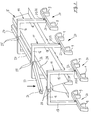
- FIG. 1 illustrates, in a perspective view of a raw ceiling 1, a cooling ceiling which is suspended from it and is denoted overall by 2, the ceiling elements 3 of which are designed as panels, engage under respective cooling pipes 4 of a pipe system and form a ceiling covering that visually hides them.
- the ceiling element 3 and the cooling tube 4 are connected in the installed position via a holding member 5, the fastening openings 7 of which are penetrated by respective connecting means (not shown) and thus the holding member 5 can be fixed to the raw ceiling 1 via a detachable connection.
- Connecting member 10 is designed as a retaining bracket 11 freely overlapping the retaining member 5, at the respective end regions 12, 13 of which at least one cooling tube 4 can be fixed directly in the installed position by means of the locking means (not shown).
- FIG. 1 shows two holding brackets 11 in different installation phases, with respective directions of movement (arrows 14 and 15) illustrating simple mounting of the holding brackets 11 that can be implemented without additional aids.
- the bracket 11 is provided with a U-shaped contour, with two starting from the base web 16, parallel holding legs 17,18 in an appropriate embodiment in the respective end regions 12,13 receive the cooling tube 4 in a receiving part 20 having the shape recess 9, the respective The mounting position can be adapted to different installation spaces in the area of the bare ceiling 1 using holding legs 17, 18 of different lengths.
- the holding legs 17, 18 and the associated receiving part 20 can be connected via respective plug-in connection means 21, 22 (FIG. 4), which enable quick and adaptable mounting to customer-specific different receiving parts 20. It is also conceivable, instead of the plug-in connection means, to provide respective snap-in connectors, pressure members or the like. Easily removable connectors if necessary, or to form the retaining bracket 11 and receiving part 20 with a one-piece connection (not shown).
- the individual representation of different recording parts 20 according to FIG. 4 illustrates that the receiving parts 20 can be provided with a plurality of shaped recesses 9 which can be connected to the holding legs 17, 18 via the respective plug connection means 21, 22, these being connected to one another in each case via a cross bar 23. It is also conceivable to provide the respective end regions 12, 13 of the holding limbs 17, 18 directly with the shaped recess 9 (not shown) for receiving the cooling tube 4 and thus to reduce the production outlay.
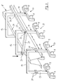
- FIGS. 2 and 3 show a plurality of holding brackets 11 which are positioned in the mounting position above the holding member 5 and which are provided with respective form attachments 25 and are connected to one another by means of a connecting strut 27 which has a corresponding counterform 26.
- the retaining bracket 11 can be stabilized with each other to a support system after pivoting into the mounting position (Fig. 1) and already before the locking of the cooling tubes 4 in the mold recesses 9 are placed on a support surface 28 of the holding member 5 so that an easily accessible Assembly position is reached.
- the respective form approaches 25 can be provided both in the area of the base web 16 (FIG. 2) and in the area of the respective holding legs 17, 18 (FIG. 3).
- the holding bracket 11 ' In one embodiment of the holding bracket 11 'according to FIG. 5, this is provided in the area of the respective holding leg 17, 18 with an intermediate carrier 30 which in the respective end area 12, 13 of the holding leg 17, 18 via the plug-in connection means 21, 22 with the holding bracket 11' connected is.
- the intermediate carrier 30 has respective shape recesses 31, in which a molded part 32, which receives the cooling tubes 4 in its shape recess 9 ', is hung.
- the molded part 32 is provided with a parallelepiped basic shape and connected to the intermediate carrier 30 via respective hook parts 33. It is also conceivable to hook any other shaped parts (not shown) into the receiving openings 31 of the intermediate carrier 30 and thus to bring the cooling tubes 4 into the corresponding locking engagement.
- the holding bracket 11 'shown in FIGS. 4 and 5 illustrates its structural design in a second embodiment, this holding bracket 11' being designed at least in regions as a telescopic part 38.
- the adjustment options illustrated with respective directions of movement (arrows 36, 37) illustrate the expedient design of the holding bracket 11 'as the telescopic part 38 which can be lengthened or shortened both in the area of the base web and in the area of the holding legs 17, 18.
- the telescopic parts 38 are provided with respective pull-out parts 39 in the region of the holding limbs 17, 18 or a pull-out part 40 in the region of the base web 16, wherein these can be pushed in or pulled out of the respective base body 41 in stages (arrows 36, 37).
- the pull-out parts 39, 40 are provided with a toothed rack 42 which determines their pull-out length and which interacts with a locking member (not shown) within the base body 41.
- bracket 11 opens up further possibilities to achieve a customer-specific adaptation of the bracket 11' in tight spaces or different installation distances in the area of a ceiling cavity formed between the ceiling 1 and the ceiling elements 3 and to assemble the pipe system quickly and with little effort, then the ceiling elements 3 in their installed position (FIG. 1) and to support the cooling tubes 4 on them in such a way that the holding brackets 11, 11 'are relieved and are raised above the contact surface 28 of the holding member 5.
- the second embodiment of the holding bracket 11 ' (FIGS. 4, 5) is provided with a vertical support 43 which can be placed on the holding member 5 in the region of the support surface 28 in the installed position and which provides a further possibility of supporting the holding bracket 11 or 11' the assembly clearly.
Landscapes
- Engineering & Computer Science (AREA)
- Combustion & Propulsion (AREA)
- General Engineering & Computer Science (AREA)
- Mechanical Engineering (AREA)
- Chemical & Material Sciences (AREA)
- Architecture (AREA)
- Physics & Mathematics (AREA)
- Life Sciences & Earth Sciences (AREA)
- Sustainable Development (AREA)
- Civil Engineering (AREA)
- Structural Engineering (AREA)
- Electromagnetism (AREA)
- Thermal Sciences (AREA)
- Supports For Pipes And Cables (AREA)
- Glass Compositions (AREA)
- Building Environments (AREA)
- Reciprocating, Oscillating Or Vibrating Motors (AREA)
- Devices For Blowing Cold Air, Devices For Blowing Warm Air, And Means For Preventing Water Condensation In Air Conditioning Units (AREA)
Applications Claiming Priority (2)
| Application Number | Priority Date | Filing Date | Title |
|---|---|---|---|
| DE9316790U | 1993-11-03 | ||
| DE9316790U DE9316790U1 (de) | 1993-11-03 | 1993-11-03 | Kühldecke |
Publications (3)
| Publication Number | Publication Date |
|---|---|
| EP0651107A2 true EP0651107A2 (fr) | 1995-05-03 |
| EP0651107A3 EP0651107A3 (fr) | 1996-09-04 |
| EP0651107B1 EP0651107B1 (fr) | 1998-12-02 |
Family
ID=6900239
Family Applications (1)
| Application Number | Title | Priority Date | Filing Date |
|---|---|---|---|
| EP94114423A Expired - Lifetime EP0651107B1 (fr) | 1993-11-03 | 1994-09-14 | Plafond réfrigérant |
Country Status (4)
| Country | Link |
|---|---|
| EP (1) | EP0651107B1 (fr) |
| AT (1) | ATE174090T1 (fr) |
| DE (2) | DE9316790U1 (fr) |
| ES (1) | ES2124825T3 (fr) |
Cited By (1)
| Publication number | Priority date | Publication date | Assignee | Title |
|---|---|---|---|---|
| EP2420749B1 (fr) | 2010-08-20 | 2017-06-28 | INTERALU, naanloze vennootschap | Système de climatisation pour un bâtiment |
Families Citing this family (3)
| Publication number | Priority date | Publication date | Assignee | Title |
|---|---|---|---|---|
| DE9316790U1 (de) * | 1993-11-03 | 1994-01-20 | Hewing GmbH, 48607 Ochtrup | Kühldecke |
| DE10148773A1 (de) * | 2001-10-02 | 2003-04-17 | Maenz Und Kraus Akustik Und Tr | Verfahren und Verbindungselement zum Aufbau von Decken mit Wärmetauschern |
| US20200149748A1 (en) * | 2018-11-14 | 2020-05-14 | Francesco Giovanni Longo | Building System |
Family Cites Families (3)
| Publication number | Priority date | Publication date | Assignee | Title |
|---|---|---|---|---|
| DE9116027U1 (de) * | 1991-12-24 | 1992-02-27 | Hewing GmbH, 4434 Ochtrup | Kühldecke |
| DE9216792U1 (de) * | 1992-12-10 | 1993-02-04 | Hewing GmbH, 4434 Ochtrup | Kühldecke |
| DE9316790U1 (de) * | 1993-11-03 | 1994-01-20 | Hewing GmbH, 48607 Ochtrup | Kühldecke |
-
1993
- 1993-11-03 DE DE9316790U patent/DE9316790U1/de not_active Expired - Lifetime
-
1994
- 1994-09-14 AT AT94114423T patent/ATE174090T1/de not_active IP Right Cessation
- 1994-09-14 EP EP94114423A patent/EP0651107B1/fr not_active Expired - Lifetime
- 1994-09-14 DE DE59407385T patent/DE59407385D1/de not_active Expired - Fee Related
- 1994-09-14 ES ES94114423T patent/ES2124825T3/es not_active Expired - Lifetime
Cited By (1)
| Publication number | Priority date | Publication date | Assignee | Title |
|---|---|---|---|---|
| EP2420749B1 (fr) | 2010-08-20 | 2017-06-28 | INTERALU, naanloze vennootschap | Système de climatisation pour un bâtiment |
Also Published As
| Publication number | Publication date |
|---|---|
| ES2124825T3 (es) | 1999-02-16 |
| ATE174090T1 (de) | 1998-12-15 |
| EP0651107A3 (fr) | 1996-09-04 |
| DE59407385D1 (de) | 1999-01-14 |
| DE9316790U1 (de) | 1994-01-20 |
| EP0651107B1 (fr) | 1998-12-02 |
Similar Documents
| Publication | Publication Date | Title |
|---|---|---|
| DE3390404T1 (de) | Verfahren zum Aufbau einer tragenden Vertäfelung und Profilglied zur Verwendung in einem derartigen Verfahren | |
| DE3232106C2 (de) | Befestigungssystem für eine vorgehängte Wand- oder Deckenverkleidung mit einer Tragschiene oder -platte | |
| EP0651107A2 (fr) | Plafond réfrigérant | |
| EP0962709B1 (fr) | Armoire d'un appareil ménager | |
| DE202004002065U1 (de) | Backofenauszug | |
| DE2409709A1 (de) | Haengedecke fuer gebaeude | |
| DE69934286T2 (de) | Rahmengestell, insbesondere für ein Elektrogerät | |
| DE4416109A1 (de) | Installationsschiene mit Reflektoranordnung für elektrische Leuchtmittel | |
| DE202007001060U1 (de) | Modulares Wandregal | |
| DE8408029U1 (de) | Eckverbinder für Dusch- oder Badewannenabtrennungen | |
| EP1232714B1 (fr) | Porte-serviettes | |
| WO2000051465A1 (fr) | Dispositif permettant de fixer des rayons d'etagere | |
| DE3007229A1 (de) | Kabelverteiler | |
| DE2405388C3 (de) | Querprofilschelle für Unterdecken | |
| DE7037254U (de) | Gestellrahmen | |
| DE3542434A1 (de) | Befestigung einer profilstange an einer basis, insbesondere fuer elektrische schalt- und/oder verteileranlagen | |
| DE8709445U1 (de) | Geräteeinbaudose für Kabelkanäle | |
| DE2042942B2 (de) | Kabelkanal- und Montageleisten-Bausatz | |
| DE8630334U1 (de) | Vorrichtung zur Befestigung einer Zaunstrebe an einem Zaunpfahl | |
| DE4235335C2 (de) | Universalhalter | |
| DE7110669U (de) | Befestigungsrahmen fur Wandbauteile und/oder Regale | |
| WO2019007580A1 (fr) | Appareil de chauffage comportant un bâti et tabouret pour un tel appareil de chauffage comportant un bâti | |
| DE1921979A1 (de) | Halter zum Anbringen des Kastens eines Rollos an der Zimmerwand oder -decke | |
| DE2157604C3 (de) | Halte- und Isoliervorrichtung für Rohrleitungen | |
| DE202006017637U1 (de) | Einrichtung für die Halterung von Gegenständen |
Legal Events
| Date | Code | Title | Description |
|---|---|---|---|
| PUAI | Public reference made under article 153(3) epc to a published international application that has entered the european phase |
Free format text: ORIGINAL CODE: 0009012 |
|
| AK | Designated contracting states |
Kind code of ref document: A2 Designated state(s): AT BE CH DE ES FR GB GR IT LI LU PT |
|
| PUAL | Search report despatched |
Free format text: ORIGINAL CODE: 0009013 |
|
| AK | Designated contracting states |
Kind code of ref document: A3 Designated state(s): AT BE CH DE ES FR GB GR IT LI LU PT |
|
| 17P | Request for examination filed |
Effective date: 19960905 |
|
| GRAG | Despatch of communication of intention to grant |
Free format text: ORIGINAL CODE: EPIDOS AGRA |
|
| 17Q | First examination report despatched |
Effective date: 19971223 |
|
| GRAG | Despatch of communication of intention to grant |
Free format text: ORIGINAL CODE: EPIDOS AGRA |
|
| GRAH | Despatch of communication of intention to grant a patent |
Free format text: ORIGINAL CODE: EPIDOS IGRA |
|
| GRAH | Despatch of communication of intention to grant a patent |
Free format text: ORIGINAL CODE: EPIDOS IGRA |
|
| GRAA | (expected) grant |
Free format text: ORIGINAL CODE: 0009210 |
|
| AK | Designated contracting states |
Kind code of ref document: B1 Designated state(s): AT BE CH DE ES FR GB GR IT LI LU PT |
|
| PG25 | Lapsed in a contracting state [announced via postgrant information from national office to epo] |
Ref country code: GR Free format text: LAPSE BECAUSE OF NON-PAYMENT OF DUE FEES Effective date: 19981202 |
|
| REF | Corresponds to: |
Ref document number: 174090 Country of ref document: AT Date of ref document: 19981215 Kind code of ref document: T |
|
| REG | Reference to a national code |
Ref country code: CH Ref legal event code: NV Representative=s name: TROESCH SCHEIDEGGER WERNER AG Ref country code: CH Ref legal event code: EP |
|
| REF | Corresponds to: |
Ref document number: 59407385 Country of ref document: DE Date of ref document: 19990114 |
|
| ET | Fr: translation filed | ||
| REG | Reference to a national code |
Ref country code: ES Ref legal event code: FG2A Ref document number: 2124825 Country of ref document: ES Kind code of ref document: T3 |
|
| GBT | Gb: translation of ep patent filed (gb section 77(6)(a)/1977) |
Effective date: 19990308 |
|
| REG | Reference to a national code |
Ref country code: PT Ref legal event code: SC4A Free format text: AVAILABILITY OF NATIONAL TRANSLATION Effective date: 19981209 |
|
| PGFP | Annual fee paid to national office [announced via postgrant information from national office to epo] |
Ref country code: PT Payment date: 19990831 Year of fee payment: 6 |
|
| PG25 | Lapsed in a contracting state [announced via postgrant information from national office to epo] |
Ref country code: LU Free format text: LAPSE BECAUSE OF NON-PAYMENT OF DUE FEES Effective date: 19990914 Ref country code: AT Free format text: LAPSE BECAUSE OF NON-PAYMENT OF DUE FEES Effective date: 19990914 |
|
| PG25 | Lapsed in a contracting state [announced via postgrant information from national office to epo] |
Ref country code: LI Free format text: LAPSE BECAUSE OF NON-PAYMENT OF DUE FEES Effective date: 19990930 Ref country code: CH Free format text: LAPSE BECAUSE OF NON-PAYMENT OF DUE FEES Effective date: 19990930 Ref country code: BE Free format text: LAPSE BECAUSE OF NON-PAYMENT OF DUE FEES Effective date: 19990930 |
|
| PLBE | No opposition filed within time limit |
Free format text: ORIGINAL CODE: 0009261 |
|
| STAA | Information on the status of an ep patent application or granted ep patent |
Free format text: STATUS: NO OPPOSITION FILED WITHIN TIME LIMIT |
|
| 26N | No opposition filed | ||
| BERE | Be: lapsed |
Owner name: HEWING G.M.B.H. Effective date: 19990930 |
|
| REG | Reference to a national code |
Ref country code: CH Ref legal event code: PL |
|
| PGFP | Annual fee paid to national office [announced via postgrant information from national office to epo] |
Ref country code: GB Payment date: 20000825 Year of fee payment: 7 |
|
| PGFP | Annual fee paid to national office [announced via postgrant information from national office to epo] |
Ref country code: FR Payment date: 20000918 Year of fee payment: 7 |
|
| PGFP | Annual fee paid to national office [announced via postgrant information from national office to epo] |
Ref country code: ES Payment date: 20000922 Year of fee payment: 7 |
|
| PGFP | Annual fee paid to national office [announced via postgrant information from national office to epo] |
Ref country code: DE Payment date: 20001018 Year of fee payment: 7 |
|
| PG25 | Lapsed in a contracting state [announced via postgrant information from national office to epo] |
Ref country code: PT Free format text: LAPSE BECAUSE OF NON-PAYMENT OF DUE FEES Effective date: 20010331 |
|
| REG | Reference to a national code |
Ref country code: PT Ref legal event code: MM4A Free format text: LAPSE DUE TO NON-PAYMENT OF FEES Effective date: 20010331 |
|
| PG25 | Lapsed in a contracting state [announced via postgrant information from national office to epo] |
Ref country code: GB Free format text: LAPSE BECAUSE OF NON-PAYMENT OF DUE FEES Effective date: 20010914 |
|
| PG25 | Lapsed in a contracting state [announced via postgrant information from national office to epo] |
Ref country code: ES Free format text: LAPSE BECAUSE OF NON-PAYMENT OF DUE FEES Effective date: 20010915 |
|
| REG | Reference to a national code |
Ref country code: GB Ref legal event code: IF02 |
|
| GBPC | Gb: european patent ceased through non-payment of renewal fee |
Effective date: 20010914 |
|
| PG25 | Lapsed in a contracting state [announced via postgrant information from national office to epo] |
Ref country code: DE Free format text: LAPSE BECAUSE OF NON-PAYMENT OF DUE FEES Effective date: 20020501 |
|
| PG25 | Lapsed in a contracting state [announced via postgrant information from national office to epo] |
Ref country code: FR Free format text: LAPSE BECAUSE OF NON-PAYMENT OF DUE FEES Effective date: 20020531 |
|
| REG | Reference to a national code |
Ref country code: FR Ref legal event code: ST |
|
| REG | Reference to a national code |
Ref country code: ES Ref legal event code: FD2A Effective date: 20021011 |
|
| PG25 | Lapsed in a contracting state [announced via postgrant information from national office to epo] |
Ref country code: IT Free format text: LAPSE BECAUSE OF NON-PAYMENT OF DUE FEES;WARNING: LAPSES OF ITALIAN PATENTS WITH EFFECTIVE DATE BEFORE 2007 MAY HAVE OCCURRED AT ANY TIME BEFORE 2007. THE CORRECT EFFECTIVE DATE MAY BE DIFFERENT FROM THE ONE RECORDED. Effective date: 20050914 |