EP0651108B1 - Eclisse pour fourrures d'ossature - Google Patents
Eclisse pour fourrures d'ossature Download PDFInfo
- Publication number
- EP0651108B1 EP0651108B1 EP94402452A EP94402452A EP0651108B1 EP 0651108 B1 EP0651108 B1 EP 0651108B1 EP 94402452 A EP94402452 A EP 94402452A EP 94402452 A EP94402452 A EP 94402452A EP 0651108 B1 EP0651108 B1 EP 0651108B1
- Authority
- EP
- European Patent Office
- Prior art keywords
- connector plate
- plate member
- aperture
- members
- furs
- Prior art date
- Legal status (The legal status is an assumption and is not a legal conclusion. Google has not performed a legal analysis and makes no representation as to the accuracy of the status listed.)
- Expired - Lifetime
Links
- 238000010276 construction Methods 0.000 abstract 1
- 238000005553 drilling Methods 0.000 description 22
- 239000002184 metal Substances 0.000 description 2
- 238000010079 rubber tapping Methods 0.000 description 2
- 230000006978 adaptation Effects 0.000 description 1
- 230000015572 biosynthetic process Effects 0.000 description 1
- 230000000694 effects Effects 0.000 description 1
- 238000004519 manufacturing process Methods 0.000 description 1
- 230000003071 parasitic effect Effects 0.000 description 1
- 239000011505 plaster Substances 0.000 description 1
Images

Classifications
-
- E—FIXED CONSTRUCTIONS
- E04—BUILDING
- E04B—GENERAL BUILDING CONSTRUCTIONS; WALLS, e.g. PARTITIONS; ROOFS; FLOORS; CEILINGS; INSULATION OR OTHER PROTECTION OF BUILDINGS
- E04B9/00—Ceilings; Construction of ceilings, e.g. false ceilings; Ceiling construction with regard to insulation
- E04B9/06—Ceilings; Construction of ceilings, e.g. false ceilings; Ceiling construction with regard to insulation characterised by constructional features of the supporting construction, e.g. cross section or material of framework members
- E04B9/065—Ceilings; Construction of ceilings, e.g. false ceilings; Ceiling construction with regard to insulation characterised by constructional features of the supporting construction, e.g. cross section or material of framework members comprising supporting beams having a folded cross-section
- E04B9/067—Ceilings; Construction of ceilings, e.g. false ceilings; Ceiling construction with regard to insulation characterised by constructional features of the supporting construction, e.g. cross section or material of framework members comprising supporting beams having a folded cross-section with inverted T-shaped cross-section
- E04B9/068—Ceilings; Construction of ceilings, e.g. false ceilings; Ceiling construction with regard to insulation characterised by constructional features of the supporting construction, e.g. cross section or material of framework members comprising supporting beams having a folded cross-section with inverted T-shaped cross-section with double web
-
- E—FIXED CONSTRUCTIONS
- E04—BUILDING
- E04B—GENERAL BUILDING CONSTRUCTIONS; WALLS, e.g. PARTITIONS; ROOFS; FLOORS; CEILINGS; INSULATION OR OTHER PROTECTION OF BUILDINGS
- E04B9/00—Ceilings; Construction of ceilings, e.g. false ceilings; Ceiling construction with regard to insulation
- E04B9/06—Ceilings; Construction of ceilings, e.g. false ceilings; Ceiling construction with regard to insulation characterised by constructional features of the supporting construction, e.g. cross section or material of framework members
- E04B9/08—Ceilings; Construction of ceilings, e.g. false ceilings; Ceiling construction with regard to insulation characterised by constructional features of the supporting construction, e.g. cross section or material of framework members having the capability of expansion, e.g. in case of fire
-
- E—FIXED CONSTRUCTIONS
- E04—BUILDING
- E04B—GENERAL BUILDING CONSTRUCTIONS; WALLS, e.g. PARTITIONS; ROOFS; FLOORS; CEILINGS; INSULATION OR OTHER PROTECTION OF BUILDINGS
- E04B9/00—Ceilings; Construction of ceilings, e.g. false ceilings; Ceiling construction with regard to insulation
- E04B9/06—Ceilings; Construction of ceilings, e.g. false ceilings; Ceiling construction with regard to insulation characterised by constructional features of the supporting construction, e.g. cross section or material of framework members
- E04B9/10—Connections between parallel members of the supporting construction
-
- E—FIXED CONSTRUCTIONS
- E04—BUILDING
- E04B—GENERAL BUILDING CONSTRUCTIONS; WALLS, e.g. PARTITIONS; ROOFS; FLOORS; CEILINGS; INSULATION OR OTHER PROTECTION OF BUILDINGS
- E04B9/00—Ceilings; Construction of ceilings, e.g. false ceilings; Ceiling construction with regard to insulation
- E04B9/06—Ceilings; Construction of ceilings, e.g. false ceilings; Ceiling construction with regard to insulation characterised by constructional features of the supporting construction, e.g. cross section or material of framework members
- E04B9/12—Connections between non-parallel members of the supporting construction
- E04B9/122—Connections between non-parallel members of the supporting construction one member passing through the other member, both members laying at least partly in the same plane
Definitions
- the present invention relates generally to the frames used for hanging plasterboard or other, for example for the realization of a ceiling, or, more precisely, a false ceiling.
- a framework is formed, on the one hand, of a first network of furs, or primary furs, which, arranged parallel to each other, are for example hung by hangers on any structure support, and, on the other hand, a second network of furs, or secondary furs, which also arranged parallel to each other, but in a direction orthogonal to that in which the primary furs extend, are snapped from place to place on these primary furs, the plates to be fixed being for example attached by screwing on the grid assembly thus formed.
- These fishplates which are to be combined with a fishplate of the same type to enclose two furs to be connected, comprise, to date, simply, at a distance from each other, two drilling zones each having at least one drilling for the passage of a fixing member, in practice a screw, at the rate of a drilling area for each of the furs to be connected.
- the primary furs connected by such fishplates are therefore to date rigidly coupled to one another.
- the splice bar (s) used do not participate in the creation of the frame concerned.
- the present invention generally relates to a provision allowing, on the contrary, such an adaptation and also leading to other advantages.
- this splint being generally characterized in that, on the one hand, one of the drilling zones being intended to allow it to be secured to one of the furs, the or the holes of the other drilling area are all elongated in the buttonhole, to allow the free passage of the fixing member (s) corollarily ensuring the fixing of the other splint to the other of the furs, and, secondly, it has a heel, for supporting a secondary fur.
- one of the splices used is secured to one of the furs to be connected and the other to the other of these.
- these fishplates are advantageously able to absorb, within the limits of these bores, the expansion of the furs which they connect, without risk of deformation for any part thereof. .
- the fire resistance is thus reinforced, which advantageously allows the assembly to be reassembled in the corresponding classification.
- the fishplates used according to the invention can also, if desired, thanks to the heel that they comprise, locally replace these furs for the support of secondary furs.
- the fishplates used according to the invention can advantageously be installed in line with the joints between plates, and these can advantageously be supported in line with these fishplates.
- the fishplates used are also advantageously suitable for another application than the only end-to-end connection of two aligned furs.
- these fishplates advantageously make it possible to connect two furs at an angle, and for example at an obtuse angle or a right angle , ensuring as previously if desired the support of the plates in line with the corresponding joint.
- the fishplates used according to the invention are also advantageously identical to each other.
- Figure 1 illustrates, by way of example, the application of the invention to the establishment of a ceiling 10, or false ceiling, consisting of plates 11 arranged side by side in the same plane.
- the plates 11 are for example plasterboard.
- plasterboard is meant here, in the usual way, plates which, essentially formed of plaster, have a sheet of cardboard on both of their faces.
- the framework 12 used to support the plates 11 is formed, on the one hand, by a first network of furs 13, or primary furs, which, established from place to place parallel to each other, are hooked by lines 14 to any support structure not shown, and, on the other hand, a second network of furs 15, or secondary furs, which, also established from place to place parallel to each other, but according to a direction orthogonal to that in which the furs 13 extend, pass continuously through these furs 13 while being snapped onto them substantially level with their lower surface.
- the plates 11 are attached by screwing onto the grid assembly which thus constitute the furs 13 and 15 jointly.
- the furs 13 are metal profiles having an I-shaped profile in cross section.
- the lower lateral wings 18 each have a square return 19 along their free edge, parallel to the central core 16.
- the furs 15, which are also metal profiles, have a partially closed U-shaped profile in cross section.
- they comprise a middle part 20 and two lateral wings 21, with, along the free edge of the latter, angled returns 22 which, parallel to the middle part 20, are directed towards one another.
- Both the middle part 20 and the lateral wings 21 have longitudinally stiffening ribs.
- jumper 24 which, by wings 25, encloses the upper lateral wings 18 of the fur 13 on which it is attached, and, on the other hand, a threaded rod 26, which is in screw connection with a nut 27 rotatably mounted on the jumper 24 while being trapped therein.
- the wings 25 of the rider 24 each extend by two legs 28, which, from one wing 25 to the other, are connected to each other by screws 29 passing through the core central 16 of the fur 13.
- the hanger 14 concerned is thus advantageously immobilized on the fur 13, and its mechanical strength is jointly advantageously reinforced, the screws 29 opposing the opening of its jumper 24.
- Each of these fishplates 30, which is to be combined with a fishplate 30 of the same type to enclose the two furs 13 to be connected, is formed of a plate 32 to be applied to the central core 16 of these furs 13 and comprises, at a distance one from the other, on this plate 32, two drilling zones 33A, 33B each having at least one bore 34A, 34B for the passage of a fixing member 35, in this case a self-tapping screw capable of screw itself into the central core 16 of the furs 13.
- one of the drilling zones 33A, 33B in this case the drilling zone 33A, being intended to allow each of the fishplates 30 to be secured to one of the furs 13,
- the hole (s) 34B of the other of the piercing zones 33A, 33B, in this case those of the piercing zone 33B are all elongated longitudinally in a buttonhole, parallel to each other, and parallel to the direction of elongation of the furs 13, to allow the free passage of the fastener (s) 35 ensuring as a corollary the joining of the other splint 30 to the other of the furs 13.
- the drilling area 33B comprises a plurality of holes 34B, arranged transversely in two columns.
- one of these columns comprises, staggered in height, three holes 34B, and the other two.
- the drilling area 33A comprises a plurality of holes 34A, arranged transversely in two columns.
- each of these columns comprises, staggered in height, three holes 34A.
- the piercing zone 33B is arranged in the immediate vicinity of one of the ends of the plate 32, and the piercing zone 33A in the immediate vicinity of the other of these ends.
- the drilling areas 33A, 33B there are, between the drilling areas 33A, 33B, at least one pair of additional holes 36, 38, of which only one, in this case the hole 36, is elongated in the buttonhole, and of which the 'other, in this case the hole 38, is arranged in alignment with the first, that is to say in alignment with the hole 36, distance from it.
- the holes 36 have the same length L, equal to that of the holes 34B.
- the holes 38 are simple round holes.
- the connecting member 37 associated with an additional bore 36, 38 is a simple bolt, that is to say a simple screw 40-nut assembly 41, the nut 41 of which is blind.
- the length of the screw 40 is such that, with the nut 41 being screwed in all the way, the fishplates 30 have sufficient play to be able to slide relative to one another on one or the other of the flanges 13 they flank.
- each of the fishplates 30 comprises a heel 42, for supporting a secondary fur 15.
- each of the fishplates 30 comprises, along its lower edge, a notch 39, and the heel 42 intervenes in the eccentric position therein.
- the notch 39 extends from the drilling area 33A to the drilling area 33B, biting lightly thereon.
- the heel 42 is eccentric in this notch 39 insofar as it is located closer to one of its ends, in practice that close to the drilling area 33A with holes 34A round, than the other of these.
- This heel 42 is in one piece with the plate 32, and extends along the plane of the latter.
- the notch 39 generally has a rectangular outline.
- each splint 30 comprises, for its stiffening, a return to square 43 which, coming from the very cutting of the '' notch 39, with, affecting itself, a cutout 44 having allowed the formation of the heel 42, extends perpendicular to the plate 32 and has, along its free edge, parallel to this plate 32, a return square 45.
- each splint 30 also includes, for its stiffening, on both sides of this notch 39, and perpendicular to its plate 32, a return to square 46.
- each splint 30 comprises, moreover, perpendicular to its plate 32, on the same side as the angle returns 43, 46 above, a U-shaped fold 48, by which it is capable of bypassing and enveloping one of the upper lateral wings 18 of the furs 13 to be connected.
- this U-shaped fold 48 which is integral with the plate 32, in continuity with the latter, is extended by a tongue 50 in the plane of this plate 32.
- each splint 30 comprises, at one of its ends, in practice that close to the drilling area 33A with round holes 34A, to form a joint 51, a hole 52, which, elongated in the buttonhole , extends in an arc around a round hole 53 on which it is centered.
- the round bore 53 extends substantially in line with the corresponding transverse edge of the plate 32, and the joint 51 forms a local extension of the latter.
- the arcuate hole 52 extends partly on the joint 51 and partly on the plate 32, between the round hole 53 and the upper edge of the latter.
- the arcuate bore 52 extends substantially over 90 °.
- the edge of the joint 51 is rounded in an arc, also being centered on the round bore 53, and it tangentially connects with the lower edge of the plate 32.
- each splint 30 comprises, for its stiffening, perpendicular to its plate 32, on the same side as the angle returns 43, 46, a return square 54, which is connected to the return square 46, in continuity therewith.
- each splint 30 comprises, for its stiffening, at the other of its transverse ends, that is to say that close to the drilling area 33B with holes 34B elongated in the buttonhole, a return at square 55, which extends perpendicular to its plate 32 over at least part of its height, and, in practice, over the whole thereof, on the same side as the returns at square 43, 46 and 54.
- the plate 32 of each splint 30 has a generally rectangular outline.
- the two fishplates 30 to be paired to connect two furs 13 are identical to each other, and, like these, they are preferably metallic.
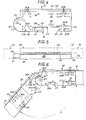
- the two ribs 30 are each arranged on each side respectively of these furs 13, as shown in solid line for one of them in FIG. 5 and as shown diagrammatically in broken lines for the other of these in this FIG. 5, and they are in practice implanted head- spade, one of these ribs 30 having its articulation 51 which extends longitudinally on a first side of the assembly and the other having its articulation 51 which extends longitudinally on the side opposite the previous one.
- Each of the ribs 30 is applied by its plate 32 to the central core 16 of the furs 13, with, on the one hand, the square return 46 present at its lower edge superimposed on the corresponding lower lateral wing 18 of these furs 13 , below the return to square 19 thereof, and, on the other hand, its U-shaped fold 48 fitted on the corresponding upper side wing 18 of these furs 13.
- each of the ribs 30 is secured to one of the furs 13 to which it is thus applied, using fastening members 35.
- Connecting members 37 are then established transversely from one to the other of the ribs 30 in favor of the holes 36, 38 thereof and of the space 56 left free between the furs 13.
- Each of the bolts constituting these connecting members 37 freely passes through a hole 36 elongated in the buttonhole of one of the ribs 30 and the corresponding round hole 38 of the other of these ribs 30.
- the furs 13 are free to slide longitudinally relative to one another within the limits of the length L of the holes 34B, 36 elongated in the buttonhole thereof.
- FIG. 6 illustrates the application of the invention to the connection, at an obtuse angle A, of two furs 13, when the plates to be fixed, not shown in this FIG. 6, belong to two panels forming a dihedral between them.
- the fishplates 30 are then attached to these furs 13 by their drilling area 33B with holes 34B elongated in the buttonhole, of course having at the opposite ends of these holes 34B the screws constituting the fixing members 35, to avoid any longitudinal play with the furs 13, and they are superimposed on each other by their articulation 51, with, established transversely between them, two bolts 37 ′, one which crosses their arcuate bores 52, duly superimposed on each other, and the other which crosses their round holes 53, also duly superimposed on each other.
- the angle A can vary for example from 90 to 270 °.
Landscapes
- Engineering & Computer Science (AREA)
- Architecture (AREA)
- Physics & Mathematics (AREA)
- Electromagnetism (AREA)
- Civil Engineering (AREA)
- Structural Engineering (AREA)
- Electrophonic Musical Instruments (AREA)
- Toys (AREA)
- Audible-Bandwidth Dynamoelectric Transducers Other Than Pickups (AREA)
- Exchange Systems With Centralized Control (AREA)
- Door And Window Frames Mounted To Openings (AREA)
- Processing Of Meat And Fish (AREA)
- Blow-Moulding Or Thermoforming Of Plastics Or The Like (AREA)
- Meat, Egg Or Seafood Products (AREA)
- Preparation Of Compounds By Using Micro-Organisms (AREA)
- Mutual Connection Of Rods And Tubes (AREA)
- Connection Of Plates (AREA)
Applications Claiming Priority (2)
| Application Number | Priority Date | Filing Date | Title |
|---|---|---|---|
| FR9312990A FR2712007B1 (fr) | 1993-11-02 | 1993-11-02 | Eclisse pour fourrures d'ossature. |
| FR9312990 | 1993-11-02 |
Publications (2)
| Publication Number | Publication Date |
|---|---|
| EP0651108A1 EP0651108A1 (fr) | 1995-05-03 |
| EP0651108B1 true EP0651108B1 (fr) | 1997-02-26 |
Family
ID=9452399
Family Applications (1)
| Application Number | Title | Priority Date | Filing Date |
|---|---|---|---|
| EP94402452A Expired - Lifetime EP0651108B1 (fr) | 1993-11-02 | 1994-10-28 | Eclisse pour fourrures d'ossature |
Country Status (6)
| Country | Link |
|---|---|
| EP (1) | EP0651108B1 (da) |
| AT (1) | ATE149226T1 (da) |
| DE (1) | DE69401805T2 (da) |
| DK (1) | DK0651108T3 (da) |
| ES (1) | ES2098110T3 (da) |
| FR (1) | FR2712007B1 (da) |
Families Citing this family (2)
| Publication number | Priority date | Publication date | Assignee | Title |
|---|---|---|---|---|
| FR2888262B1 (fr) * | 2005-07-08 | 2008-12-05 | Saint Gobain Isover Sa | Element de raccordement de fourrures pour doublage de paroi |
| CN116900354B (zh) * | 2023-08-02 | 2025-10-31 | 安徽齐天文具制造有限公司 | 一种快劳夹马勾钻孔加工设备 |
Family Cites Families (10)
| Publication number | Priority date | Publication date | Assignee | Title |
|---|---|---|---|---|
| FR999487A (fr) * | 1949-10-27 | 1952-01-31 | Boefrancex Soc | Faux-plafond en panneaux rigides munis ou non d'un cadre métallique |
| US3189138A (en) * | 1961-10-24 | 1965-06-15 | Eastern Prod Corp | Ceiling construction |
| FR1340782A (fr) * | 1961-12-14 | 1963-10-18 | Rollform | Armature quadrillée pour plafond acoustique dans laquelle on rend possible la dilatation thermique de ladite armature |
| GB1057551A (en) * | 1963-07-17 | 1967-02-01 | Robert Paul Lickliter | Improvements in expansion joints |
| GB1031060A (en) * | 1963-12-16 | 1966-05-25 | Bowaters Pulp & Paper Mills | Improvements in or relating to ceiling structures |
| US3457688A (en) * | 1965-05-03 | 1969-07-29 | Eastern Prod Corp | Suspended ceiling |
| US3390503A (en) * | 1965-09-10 | 1968-07-02 | Armstrong Cork Co | Thermally responsive beam joint |
| US3565474A (en) * | 1969-02-14 | 1971-02-23 | Conwed Corp | Exposed-type suspension system |
| FR2578570B1 (fr) * | 1985-03-08 | 1988-04-22 | Placoplatre Sa | Fourrure pour ossature primaire de faux plafond, et suspente propre a la suspension d'une telle fourrure |
| DE4032884A1 (de) * | 1990-10-17 | 1992-04-30 | Karl Hans Koch | Profilrasterdecke fuer wohn-, geschaefts-, ausstellungsraeumen o. dgl. |
-
1993
- 1993-11-02 FR FR9312990A patent/FR2712007B1/fr not_active Expired - Fee Related
-
1994
- 1994-10-28 DK DK94402452.0T patent/DK0651108T3/da active
- 1994-10-28 EP EP94402452A patent/EP0651108B1/fr not_active Expired - Lifetime
- 1994-10-28 ES ES94402452T patent/ES2098110T3/es not_active Expired - Lifetime
- 1994-10-28 DE DE69401805T patent/DE69401805T2/de not_active Expired - Lifetime
- 1994-10-28 AT AT94402452T patent/ATE149226T1/de active
Also Published As
| Publication number | Publication date |
|---|---|
| DE69401805D1 (de) | 1997-04-03 |
| ES2098110T3 (es) | 1997-04-16 |
| FR2712007B1 (fr) | 1996-01-12 |
| DK0651108T3 (da) | 1997-09-01 |
| FR2712007A1 (fr) | 1995-05-12 |
| ATE149226T1 (de) | 1997-03-15 |
| DE69401805T2 (de) | 1997-06-05 |
| EP0651108A1 (fr) | 1995-05-03 |
Similar Documents
| Publication | Publication Date | Title |
|---|---|---|
| US6732409B2 (en) | Hinge mounting system | |
| FR2694952A1 (fr) | Système pour la fixation d'un raidisseur de mur-rideau sur un élément de construction. | |
| FR2552174A1 (fr) | Dispositif de fixation reglable pour plaques de parement | |
| FR2520781A1 (fr) | Cloison formee de panneaux montes sur armatures et panneau susceptible d'etre utilise pour la realisation d'une telle cloison | |
| WO2006123062A2 (fr) | Piece de liaison et ensemble de pieces de liaison orientables | |
| EP0494122B1 (fr) | Suspente articulée | |
| FR2549933A1 (fr) | Poutre profilee en forme d'i, attaches et assemblages pour de telles poutres | |
| EP0651108B1 (fr) | Eclisse pour fourrures d'ossature | |
| EP0227514A1 (fr) | Système support d'éléments d'habillage de façade, en particulier de caissons en tôle pliée | |
| EP1099029A1 (fr) | Glissiere de securite bois sur appuis a entraxes variables | |
| EP1042571B1 (fr) | Barre de seuil a rattrapage de niveau | |
| EP1498995A1 (fr) | Console de support d'un chemin de câbles | |
| FR2640301A1 (fr) | Dispositif pour la liaison de poutres de constructions prefabriquees en treillis | |
| CH669814A5 (da) | ||
| FR2922237A1 (fr) | Attache pour panneaux de faux-plafonds. | |
| EP0711882B1 (fr) | Structure porteuse pour plafond démontable et suspente mise en oeuvre dans une telle structure porteuse | |
| EP1086323B1 (fr) | Agrafe pour bande transporteuse a fixation par vis | |
| FR2762630A1 (fr) | Grille pour la construction d'un faux plafond suspendu | |
| EP0762585B1 (fr) | Accessoire de support pour l'assujettissement d'un barreau à un autre élément de châssis,notamment pour le support d'appareils électriques | |
| FR3065983B1 (fr) | Structure de verriere pourvue de cales pour assemblage vertical de montants sur des traverses | |
| FR3034823A1 (fr) | Dispositif de liaison de profiles, notamment pour la realisation de structures et plus particulierement de pergolas, structures obtenues | |
| FR2711695A1 (fr) | Suspente pour profilé de grande portée, notamment pour la réalisation de faux-plafonds. | |
| FR2760250A1 (fr) | Structure porteuse pour cloison de relativement grande hauteur | |
| FR2898628A1 (fr) | Ensemble de fixation pour vantail comprenant au moins une patte d'articulation et une patte de fixation independantes l'une de l'autre | |
| FR2711745A1 (fr) | Etrier réglable. |
Legal Events
| Date | Code | Title | Description |
|---|---|---|---|
| PUAI | Public reference made under article 153(3) epc to a published international application that has entered the european phase |
Free format text: ORIGINAL CODE: 0009012 |
|
| AK | Designated contracting states |
Kind code of ref document: A1 Designated state(s): AT BE CH DE DK ES FR GB IT LI SE |
|
| 17P | Request for examination filed |
Effective date: 19950415 |
|
| GRAG | Despatch of communication of intention to grant |
Free format text: ORIGINAL CODE: EPIDOS AGRA |
|
| 17Q | First examination report despatched |
Effective date: 19960117 |
|
| GRAH | Despatch of communication of intention to grant a patent |
Free format text: ORIGINAL CODE: EPIDOS IGRA |
|
| GRAH | Despatch of communication of intention to grant a patent |
Free format text: ORIGINAL CODE: EPIDOS IGRA |
|
| GRAA | (expected) grant |
Free format text: ORIGINAL CODE: 0009210 |
|
| AK | Designated contracting states |
Kind code of ref document: B1 Designated state(s): AT BE CH DE DK ES FR GB IT LI SE |
|
| REF | Corresponds to: |
Ref document number: 149226 Country of ref document: AT Date of ref document: 19970315 Kind code of ref document: T |
|
| ITF | It: translation for a ep patent filed | ||
| REG | Reference to a national code |
Ref country code: CH Ref legal event code: NV Representative=s name: E. BLUM & CO. PATENTANWAELTE Ref country code: CH Ref legal event code: EP |
|
| GBT | Gb: translation of ep patent filed (gb section 77(6)(a)/1977) |
Effective date: 19970228 |
|
| REF | Corresponds to: |
Ref document number: 69401805 Country of ref document: DE Date of ref document: 19970403 |
|
| REG | Reference to a national code |
Ref country code: ES Ref legal event code: FG2A Ref document number: 2098110 Country of ref document: ES Kind code of ref document: T3 |
|
| REG | Reference to a national code |
Ref country code: DK Ref legal event code: T3 |
|
| PLBE | No opposition filed within time limit |
Free format text: ORIGINAL CODE: 0009261 |
|
| STAA | Information on the status of an ep patent application or granted ep patent |
Free format text: STATUS: NO OPPOSITION FILED WITHIN TIME LIMIT |
|
| 26N | No opposition filed | ||
| REG | Reference to a national code |
Ref country code: GB Ref legal event code: IF02 |
|
| REG | Reference to a national code |
Ref country code: CH Ref legal event code: PFA Owner name: PLACOPLATRE Free format text: PLACOPLATRE#34 AVENUE FRANKLIN ROOSEVELT#92282 SURESNES CEDEX (FR) -TRANSFER TO- PLACOPLATRE#34 AVENUE FRANKLIN ROOSEVELT#92282 SURESNES CEDEX (FR) |
|
| PGFP | Annual fee paid to national office [announced via postgrant information from national office to epo] |
Ref country code: AT Payment date: 20101027 Year of fee payment: 17 |
|
| PGFP | Annual fee paid to national office [announced via postgrant information from national office to epo] |
Ref country code: DE Payment date: 20101012 Year of fee payment: 17 |
|
| PGFP | Annual fee paid to national office [announced via postgrant information from national office to epo] |
Ref country code: IT Payment date: 20101027 Year of fee payment: 17 Ref country code: GB Payment date: 20101018 Year of fee payment: 17 |
|
| PGFP | Annual fee paid to national office [announced via postgrant information from national office to epo] |
Ref country code: DK Payment date: 20110919 Year of fee payment: 18 Ref country code: CH Payment date: 20110923 Year of fee payment: 18 |
|
| PGFP | Annual fee paid to national office [announced via postgrant information from national office to epo] |
Ref country code: ES Payment date: 20110927 Year of fee payment: 18 Ref country code: SE Payment date: 20110926 Year of fee payment: 18 |
|
| PGFP | Annual fee paid to national office [announced via postgrant information from national office to epo] |
Ref country code: BE Payment date: 20111028 Year of fee payment: 18 |
|
| PGFP | Annual fee paid to national office [announced via postgrant information from national office to epo] |
Ref country code: FR Payment date: 20121122 Year of fee payment: 19 |
|
| BERE | Be: lapsed |
Owner name: *PLACOPLATRE Effective date: 20121031 |
|
| REG | Reference to a national code |
Ref country code: CH Ref legal event code: PL |
|
| REG | Reference to a national code |
Ref country code: DK Ref legal event code: EBP |
|
| REG | Reference to a national code |
Ref country code: AT Ref legal event code: MM01 Ref document number: 149226 Country of ref document: AT Kind code of ref document: T Effective date: 20121028 |
|
| GBPC | Gb: european patent ceased through non-payment of renewal fee |
Effective date: 20121028 |
|
| PG25 | Lapsed in a contracting state [announced via postgrant information from national office to epo] |
Ref country code: CH Free format text: LAPSE BECAUSE OF NON-PAYMENT OF DUE FEES Effective date: 20121031 Ref country code: LI Free format text: LAPSE BECAUSE OF NON-PAYMENT OF DUE FEES Effective date: 20121031 Ref country code: SE Free format text: LAPSE BECAUSE OF NON-PAYMENT OF DUE FEES Effective date: 20121029 Ref country code: GB Free format text: LAPSE BECAUSE OF NON-PAYMENT OF DUE FEES Effective date: 20121028 Ref country code: AT Free format text: LAPSE BECAUSE OF NON-PAYMENT OF DUE FEES Effective date: 20121028 Ref country code: DE Free format text: LAPSE BECAUSE OF NON-PAYMENT OF DUE FEES Effective date: 20130501 Ref country code: BE Free format text: LAPSE BECAUSE OF NON-PAYMENT OF DUE FEES Effective date: 20121031 |
|
| REG | Reference to a national code |
Ref country code: DE Ref legal event code: R119 Ref document number: 69401805 Country of ref document: DE Effective date: 20130501 |
|
| PG25 | Lapsed in a contracting state [announced via postgrant information from national office to epo] |
Ref country code: IT Free format text: LAPSE BECAUSE OF NON-PAYMENT OF DUE FEES Effective date: 20121028 |
|
| PG25 | Lapsed in a contracting state [announced via postgrant information from national office to epo] |
Ref country code: DK Free format text: LAPSE BECAUSE OF NON-PAYMENT OF DUE FEES Effective date: 20121031 |
|
| REG | Reference to a national code |
Ref country code: ES Ref legal event code: FD2A Effective date: 20140116 |
|
| PG25 | Lapsed in a contracting state [announced via postgrant information from national office to epo] |
Ref country code: ES Free format text: LAPSE BECAUSE OF NON-PAYMENT OF DUE FEES Effective date: 20121029 |
|
| REG | Reference to a national code |
Ref country code: FR Ref legal event code: ST Effective date: 20140630 |
|
| PG25 | Lapsed in a contracting state [announced via postgrant information from national office to epo] |
Ref country code: FR Free format text: LAPSE BECAUSE OF NON-PAYMENT OF DUE FEES Effective date: 20131031 |