EP0651113B1 - Dispositif de fixation d'éléments de façade en forme de panneaux - Google Patents
Dispositif de fixation d'éléments de façade en forme de panneaux Download PDFInfo
- Publication number
- EP0651113B1 EP0651113B1 EP93112115A EP93112115A EP0651113B1 EP 0651113 B1 EP0651113 B1 EP 0651113B1 EP 93112115 A EP93112115 A EP 93112115A EP 93112115 A EP93112115 A EP 93112115A EP 0651113 B1 EP0651113 B1 EP 0651113B1
- Authority
- EP
- European Patent Office
- Prior art keywords
- pane
- elements
- additional
- fastening
- outer part
- Prior art date
- Legal status (The legal status is an assumption and is not a legal conclusion. Google has not performed a legal analysis and makes no representation as to the accuracy of the status listed.)
- Expired - Lifetime
Links
Images


Classifications
-
- E—FIXED CONSTRUCTIONS
- E04—BUILDING
- E04F—FINISHING WORK ON BUILDINGS, e.g. STAIRS, FLOORS
- E04F13/00—Coverings or linings, e.g. for walls or ceilings
- E04F13/07—Coverings or linings, e.g. for walls or ceilings composed of covering or lining elements; Sub-structures therefor; Fastening means therefor
- E04F13/08—Coverings or linings, e.g. for walls or ceilings composed of covering or lining elements; Sub-structures therefor; Fastening means therefor composed of a plurality of similar covering or lining elements
- E04F13/0801—Separate fastening elements
- E04F13/0803—Separate fastening elements with load-supporting elongated furring elements between wall and covering elements
- E04F13/081—Separate fastening elements with load-supporting elongated furring elements between wall and covering elements with additional fastening elements between furring elements and covering elements
- E04F13/0814—Separate fastening elements with load-supporting elongated furring elements between wall and covering elements with additional fastening elements between furring elements and covering elements fixed by means of clamping action
-
- F—MECHANICAL ENGINEERING; LIGHTING; HEATING; WEAPONS; BLASTING
- F24—HEATING; RANGES; VENTILATING
- F24S—SOLAR HEAT COLLECTORS; SOLAR HEAT SYSTEMS
- F24S25/00—Arrangement of stationary mountings or supports for solar heat collector modules
- F24S25/60—Fixation means, e.g. fasteners, specially adapted for supporting solar heat collector modules
- F24S25/67—Fixation means, e.g. fasteners, specially adapted for supporting solar heat collector modules for coupling adjacent modules or their peripheral frames
-
- H—ELECTRICITY
- H10—SEMICONDUCTOR DEVICES; ELECTRIC SOLID-STATE DEVICES NOT OTHERWISE PROVIDED FOR
- H10F—INORGANIC SEMICONDUCTOR DEVICES SENSITIVE TO INFRARED RADIATION, LIGHT, ELECTROMAGNETIC RADIATION OF SHORTER WAVELENGTH OR CORPUSCULAR RADIATION
- H10F19/00—Integrated devices, or assemblies of multiple devices, comprising at least one photovoltaic cell covered by group H10F10/00, e.g. photovoltaic modules
- H10F19/80—Encapsulations or containers for integrated devices, or assemblies of multiple devices, having photovoltaic cells
-
- Y—GENERAL TAGGING OF NEW TECHNOLOGICAL DEVELOPMENTS; GENERAL TAGGING OF CROSS-SECTIONAL TECHNOLOGIES SPANNING OVER SEVERAL SECTIONS OF THE IPC; TECHNICAL SUBJECTS COVERED BY FORMER USPC CROSS-REFERENCE ART COLLECTIONS [XRACs] AND DIGESTS
- Y02—TECHNOLOGIES OR APPLICATIONS FOR MITIGATION OR ADAPTATION AGAINST CLIMATE CHANGE
- Y02B—CLIMATE CHANGE MITIGATION TECHNOLOGIES RELATED TO BUILDINGS, e.g. HOUSING, HOUSE APPLIANCES OR RELATED END-USER APPLICATIONS
- Y02B10/00—Integration of renewable energy sources in buildings
- Y02B10/10—Photovoltaic [PV]
-
- Y—GENERAL TAGGING OF NEW TECHNOLOGICAL DEVELOPMENTS; GENERAL TAGGING OF CROSS-SECTIONAL TECHNOLOGIES SPANNING OVER SEVERAL SECTIONS OF THE IPC; TECHNICAL SUBJECTS COVERED BY FORMER USPC CROSS-REFERENCE ART COLLECTIONS [XRACs] AND DIGESTS
- Y02—TECHNOLOGIES OR APPLICATIONS FOR MITIGATION OR ADAPTATION AGAINST CLIMATE CHANGE
- Y02B—CLIMATE CHANGE MITIGATION TECHNOLOGIES RELATED TO BUILDINGS, e.g. HOUSING, HOUSE APPLIANCES OR RELATED END-USER APPLICATIONS
- Y02B10/00—Integration of renewable energy sources in buildings
- Y02B10/20—Solar thermal
-
- Y—GENERAL TAGGING OF NEW TECHNOLOGICAL DEVELOPMENTS; GENERAL TAGGING OF CROSS-SECTIONAL TECHNOLOGIES SPANNING OVER SEVERAL SECTIONS OF THE IPC; TECHNICAL SUBJECTS COVERED BY FORMER USPC CROSS-REFERENCE ART COLLECTIONS [XRACs] AND DIGESTS
- Y02—TECHNOLOGIES OR APPLICATIONS FOR MITIGATION OR ADAPTATION AGAINST CLIMATE CHANGE
- Y02E—REDUCTION OF GREENHOUSE GAS [GHG] EMISSIONS, RELATED TO ENERGY GENERATION, TRANSMISSION OR DISTRIBUTION
- Y02E10/00—Energy generation through renewable energy sources
- Y02E10/40—Solar thermal energy, e.g. solar towers
- Y02E10/47—Mountings or tracking
-
- Y—GENERAL TAGGING OF NEW TECHNOLOGICAL DEVELOPMENTS; GENERAL TAGGING OF CROSS-SECTIONAL TECHNOLOGIES SPANNING OVER SEVERAL SECTIONS OF THE IPC; TECHNICAL SUBJECTS COVERED BY FORMER USPC CROSS-REFERENCE ART COLLECTIONS [XRACs] AND DIGESTS
- Y02—TECHNOLOGIES OR APPLICATIONS FOR MITIGATION OR ADAPTATION AGAINST CLIMATE CHANGE
- Y02E—REDUCTION OF GREENHOUSE GAS [GHG] EMISSIONS, RELATED TO ENERGY GENERATION, TRANSMISSION OR DISTRIBUTION
- Y02E10/00—Energy generation through renewable energy sources
- Y02E10/50—Photovoltaic [PV] energy
Definitions
- the invention relates to a device for fastening plate-shaped elements, in particular for facade or roof cladding on support elements fastened to a building wall or a roof by means of fastening elements, which are each formed by an outer part and an inner part, of which the outer or inner part with a Footprint for the edge of a plate-shaped element and the outer part is each provided with a contact surface for this and an adjacent plate-shaped element and which are arranged together on a screw bolt, which is held by the respective support element and a positive connection between the outer part and inner part by pressing Fastener and support element manufactures.
- Fastening devices of the type described above are known from EP-A3-0 415 201 and EP application 93 100 614.2. These have the advantage that facade cladding made of prefabricated plate-shaped facade elements such as glasses, metals, natural stones and other suitable materials can be erected with a minimum of parts within the shortest possible time and with little effort, the fastening devices being able to easily compensate for both the on-site dimensional deviations as well as the manufacturing tolerances of the facade elements.
- the load of the facade elements is transferred to the building wall by positive locking, so that the bolts of the fastening elements only have to take up the wind and possibly the scaffolding loads and have to ensure the structural positive locking.
- the invention has for its object to avoid the disadvantages of the known constructions described above and to further develop them in such a way that multi-pane plate-shaped elements for facade or roof cladding can be attached without the risk of damage to the panes.
- each fastening element with an additional contact surface for the edge of the outermost pane offset from the edge of the load-bearing rearmost pane towards the center of the pane and with additional contact surfaces for this outermost pane and for the outermost pane of the adjacent element is provided, the distance of the additional contact surfaces from the inner part being greater than that in the assembled state Total thickness of the at least two-pane element.
- the additional contact and contact surfaces are formed on the outer part of the fastening element.
- the side facing the inner part is step-shaped, the load-bearing rear disc standing on the lower shoulder closer to the screw bolt and the outermost disc or outer discs standing on the upper shoulder offset towards the center of the supporting disc.
- the additional contact and contact surfaces are formed on an additional part which is arranged in a form-fitting manner on the outer part of the fastening element and is also held by the screw bolt.
- the additional part is arranged either between the outer and inner part of the fastening element or on the outside of the outer part of the fastening element.
- These additional parts are designed according to the invention so that they have bends for positive engagement with the outer part. Because of the bends, the additional part is supported on the outer part on the one hand and on the other hand these bends form the additional contact and contact surfaces for the outermost panes.
- the two-pane elements are designed as multi-pane glasses, two-pane safety glasses, with insulating glasses designed with an evacuated intermediate space or as photovoltaic elements, with an intermediate layer consisting of these photovoltaic elements between the supporting rear pane and an outer cover pane Plastic is arranged, embedded in the interconnected silicon cells for the direct conversion of light energy into electrical energy.
- the rear supporting pane is preferably made of single-pane safety glass and the outer cover pane is made of white glass.
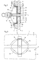
- the fastening device essentially consists of a support element 1 and a fastening element 2, the support element 1 in the exemplary embodiment being formed by two C profiles 1a and 1b lying one inside the other, the webs of which lie one on top of the other and the angled ones thereof Leg ends form a guide 3 separated by a slot.
- a screw bolt 4 is slidably guided, which in the exemplary embodiment is provided with a hammer head 4a and in this way is guided non-rotatably in the support element 1.
- the support element 1 is fastened to a building wall 6 by means of screws 5.
- Each fastening element 2 consists of an inner part 2a and an outer part 2b, which are arranged together on the screw bolt 4.
- each outer part 2b is provided with a contact surface 2c for a plate-shaped element 7.
- This contact surface 2c can alternatively also be formed on the inner part 2a.
- the contact area 2c on the outer part 2b is created by repeatedly cranking the outer part 2b. The cranking is carried out with a depth which corresponds to the thickness of the element 7 to be fastened in the region of its contact edge. The height of the offset corresponds to the distance between the adjacent elements 7, i. H. the joint formed between adjacent elements 7.
- each outer part 2b forms a contact surface 2d for the upper and for the lower element 7. While the load of the plate-shaped element 7 standing on the outer part 2b in each case is absorbed via the contact surface 2c, the contact surfaces 2d support those on the plate-shaped elements 7 exerted wind forces, namely via the bolts 4 in the support elements 1, which are fastened to the building wall 6 as described.
- FIG. 1 To accommodate at least two-pane, in the exemplary embodiment three-pane elements 7, in the exemplary embodiment shown in FIG. 1 there is a fastening device on the outside of the outer part 2b of the fastening element 2 an additional part 8 is arranged, which has an additional contact surface 8a and additional contact surfaces 8b for setting up and holding the outermost pane 9 of a three-pane element 7.
- the additional part 8 is formed by multiple crimping so that bends 10 in the fully assembled state guarantee the positive connection of the additional part 8 with the outer part 2b.
- the additional part 8 is arranged on the outside of the outer part 2b within a U-shaped reinforcing web 2e and lies in a form-fitting manner on the upper and lower edge of the folds 10a formed by double bending Outer part 2b.
- the lower fold 10a can be omitted because loads are only transferred via the upper fold 10a, whereas only wind forces act from the side below. By eliminating the lower fold 10a, air space for accommodating dimensional deviations in the manufacture of the pane is obtained.
- a rearmost disc 11 of a three-disc element 7 is pressed as a supporting disc between the inner part 2a and the outer part 2b of the fastener 2 when a ring eyelet nut 12, for example, is provided as a scaffold eyelet that the fastening element 2 consisting of outer part 2b and inner part 2a is pressed against the supporting element 1.
- a smooth-walled sleeve 13 is used as a spacer sleeve.
- the distance between the additional contact surfaces 8b from the inner part 2a is greater than the total thickness of the three-disc element 7. This greater distance guarantees that the outermost disc 9 does not absorb any pressing forces. This is particularly important if the three-pane element 7 is designed as a photovoltaic element, wherein A plastic intermediate layer 14 is arranged between the rearmost pane 11 and the outermost pane serving as a cover, in which the interconnected silicon cells are embedded for the direct conversion of light into electrical energy.
- an elastic intermediate layer 15 which is preferably made of plastic or rubber.
- the additional part 8 is arranged on the inside of the outer part 2b of the fastening element 2.
- the additional part 8 is formed by multiple cranking so that the bends 10 form fit on the one hand against the inner surface of the outer part 2b and on the other hand form the additional contact surfaces 8a and additional contact surfaces 8b.
- the third embodiment of a fastening element 2 shown in FIG. 5 is characterized in that it does not require an additional part 8, since the additional contact surfaces 8a and the additional contact surfaces 8b are formed on the inside of the outer part 2b.
- the inside of the outer part 2b of the fastening element 2 is step-shaped in such a way that a lower shoulder forms the contact surface 2c and an upper shoulder forms the additional contact surface 8a for the outermost disk 9.
- the depth of the uppermost heel is in turn designed such that in the fully assembled state of the fastening element 2 only the rearmost pane 11 is pressed between the outer part 2b and the inner part 2a (with the interposition of an intermediate layer 15), but the outermost one Disk 9 is only secured against tipping by the additional contact surface 8b, but is not clamped.
- screws 16 are used, which can be seen in FIG. 1. These preferably self-tapping screws 16 are screwed into holes 1c, which are drilled in the support element 1 after the fastening element 2 has been aligned by moving the screw bolt 4 in the guide 3. The loads resulting from the elements 7 standing on the contact surfaces 2c and 8a are thus introduced into the supporting element 1 in a form-fitting manner by means of the screws 16 which are subjected to shear.
- the offset of the edge 9a of the outermost disk 9 cooperating with the additional contact surface 8a compared to the edge 11a of the rearmost disk 11 standing on the contact surface 2c is not only due to a corresponding offset of the complete lower edge of the Discs 9 and 11 can be achieved, but by semicircular recesses 9b formed in the outermost disc 9. These recesses 9b ensure that the outer parts 2b can be placed on the inner parts 2a and clamped by means of the screw bolt 4 without undesired clamping of the outermost washer 9 and intermediate layers 14.
Landscapes
- Engineering & Computer Science (AREA)
- Architecture (AREA)
- Mechanical Engineering (AREA)
- General Engineering & Computer Science (AREA)
- Sustainable Energy (AREA)
- Thermal Sciences (AREA)
- Chemical & Material Sciences (AREA)
- Combustion & Propulsion (AREA)
- Physics & Mathematics (AREA)
- Sustainable Development (AREA)
- Life Sciences & Earth Sciences (AREA)
- Civil Engineering (AREA)
- Structural Engineering (AREA)
- Load-Bearing And Curtain Walls (AREA)
- Finishing Walls (AREA)
- Joining Of Building Structures In Genera (AREA)
Claims (8)
- Dispositif de fixation d'éléments en forme de plaques (7), en particulier pour garnir des façades ou des toitures, sur des éléments porteurs (1) fixés à un mur (6) de bâtiment ou à une toiture, au moyen d'éléments de fixation (2) qui sont formés chacun d'une partie extérieure (2b) et d'une partie intérieure (2a), dont la partie extérieure ou intérieure (2b, 2a) comporte une surface d'appui horizontale (2c) pour le bord d'un élément en forme de plaque (7) et la partie extérieure correspondante (2b) comporte une surface d'appui verticale (2d) pour ce même élément et pour un élément en forme de plaque (7) voisin, et qui sont disposés conjointement sur un boulon fileté (4) qui est retenu par l'élément porteur correspondant (1) et qui, en serrant la partie extérieure (2b) et la partie intérieure (2a) l'une contre l'autre, crée une liaison par conjugaison de formes entre l'élément de fixation (2) et l'élément porteur (1), caractérisé en ce que, pour fixer des éléments à au moins deux vitres (7), chaque élément de fixation (2) comporte une surface d'appui horizontale supplémentaire (8a) pour le bord (9a) de la vitre extérieure extrême (9) décalé vers le centre de la vitre par rapport au bord (11a) de la vitre porteuse (11) située le plus à l'arrière, et comporte des surfaces d'appui verticales supplémentaires (8b) pour cette vitre extérieure extrême (9) et pour la vitre extérieure extrême (9) de l'élément voisin (7), l'écartement entre les surfaces d'appui verticales supplémentaires (8b) et la partie intérieure (2a) étant, en position montée, supérieur à l'épaisseur totale de l'élément à au moins deux vitres (7).
- Dispositif selon la revendication 1, caractérisé en ce que les surfaces d'appui horizontales et verticales supplémentaires (8a, 8b) sont réalisées sur la partie extérieure (2b) de l'élément de fixation (2).
- Dispositif selon la revendication 1, caractérisé en ce que les surfaces d'appui horizontales et verticales supplémentaires (8a, 8b) sont réalisées sur une partie supplémentaire (8) qui est disposée par conjugaison de formes contre la partie extérieure (2b) de l'élément de fixation (2) et est également maintenue par le boulon fileté (4).
- Dispositif selon la revendication 3, caractérisé en ce que la partie supplémentaire (8) est placée entre les parties extérieure et intérieure (2b, 2a) de l'élément de fixation (2).
- Dispositif selon la revendication 3, caractérisé en ce que la partie supplémentaire (8) est placée sur la face extérieure de la partie extérieure (2b) de l'élément de fixation (2).
- Dispositif selon la revendication 4 ou 5, caractérisé en ce que la partie supplémentaire (8) est conçue avec des portions coudées (10) permettant de l'appliquer par conjugaison de formes contre la partie extérieure (2b) de l'élément de fixation (2).
- Dispositif selon au moins l'une des revendications 1 à 6, caractérisé en ce que des garnitures intermédiaires élastiques (15) sont disposées entre les surfaces d'appui horizontales et/ou verticales (2c, 8a, 2d, 8b) destinées aux vitres arrière extrême et extérieure extrême (11, 9) de l'élément (7) à au moins deux vitres.
- Dispositif selon au moins l'une des revendications 1 à 7, caractérisé en ce que les éléments à deux vitres (7) sont conçus sous la forme de verres à plusieurs vitres, de verres de sécurité à deux vitres, de verres isolants séparés par un interstice où est réalisé un vide partiel, ou d'éléments photovoltaïques qui, entre la vitre porteuse arrière (11), de préférence en verre de sécurité à une vitre, et une vitre de recouvrement extérieure (9), de préférence en verre blanc, comportent une garniture intermédiaire (14) en matière synthétique dans laquelle des cellules au silicium reliées entre elles sont noyées pour convertir directement l'énergie lumineuse en énergie électrique.
Priority Applications (3)
| Application Number | Priority Date | Filing Date | Title |
|---|---|---|---|
| AT93112115T ATE132559T1 (de) | 1993-07-29 | 1993-07-29 | Vorrichtung zur befestigung von plattenförmigen fassadenelementen |
| EP93112115A EP0651113B1 (fr) | 1993-07-29 | 1993-07-29 | Dispositif de fixation d'éléments de façade en forme de panneaux |
| DE59301363T DE59301363D1 (de) | 1993-07-29 | 1993-07-29 | Vorrichtung zur Befestigung von plattenförmigen Fassadenelementen |
Applications Claiming Priority (1)
| Application Number | Priority Date | Filing Date | Title |
|---|---|---|---|
| EP93112115A EP0651113B1 (fr) | 1993-07-29 | 1993-07-29 | Dispositif de fixation d'éléments de façade en forme de panneaux |
Publications (2)
| Publication Number | Publication Date |
|---|---|
| EP0651113A1 EP0651113A1 (fr) | 1995-05-03 |
| EP0651113B1 true EP0651113B1 (fr) | 1996-01-03 |
Family
ID=8213122
Family Applications (1)
| Application Number | Title | Priority Date | Filing Date |
|---|---|---|---|
| EP93112115A Expired - Lifetime EP0651113B1 (fr) | 1993-07-29 | 1993-07-29 | Dispositif de fixation d'éléments de façade en forme de panneaux |
Country Status (3)
| Country | Link |
|---|---|
| EP (1) | EP0651113B1 (fr) |
| AT (1) | ATE132559T1 (fr) |
| DE (1) | DE59301363D1 (fr) |
Cited By (3)
| Publication number | Priority date | Publication date | Assignee | Title |
|---|---|---|---|---|
| GB2374615A (en) * | 2001-03-14 | 2002-10-23 | Saint Gobain Isover | Element for adjustably mounting facing panels |
| WO2004011755A1 (fr) | 2002-07-31 | 2004-02-05 | E.I. Du Pont De Nemours And Company | Systemes de point de fixation pour verre feuillete et procede de realisation |
| DE102007013509A1 (de) * | 2007-02-22 | 2008-08-28 | Fischerwerke Gmbh & Co. Kg | Befestigungsvorrichtung |
Families Citing this family (7)
| Publication number | Priority date | Publication date | Assignee | Title |
|---|---|---|---|---|
| FR2738857B1 (fr) * | 1995-09-19 | 1997-11-21 | Alcan France | Dispositif de support d'un element en porte a faux vis-a-vis de la facade verticale d'un mur rideau d'un batiment ou construction analogue |
| DE20003056U1 (de) | 2000-02-19 | 2000-04-20 | Lennep, Ekkehard Jatzlau von, Dipl.-Ing., 40882 Ratingen | Befestigungsvorrichtung für plattenförmige Fassadenelemente |
| AU4629200A (en) * | 2000-05-22 | 2001-12-03 | Andrzej Potyka | Device for fixing cladding panels |
| DE10056177B4 (de) * | 2000-11-13 | 2004-07-08 | Wolfgang Fechner | Befestigungsvorrichtung für plattenförmige Fassadenelemente |
| DE10111246A1 (de) * | 2001-03-09 | 2002-09-12 | Schuler Joerg | Fassadenverkleidung aus plattenförmigen Fassadenelementen |
| US8973316B2 (en) * | 2005-10-07 | 2015-03-10 | Franz Safford | Sectional construction assemblies |
| US8769901B2 (en) | 2010-05-28 | 2014-07-08 | The Diller Corporation | Cladding system for building laminates |
Family Cites Families (7)
| Publication number | Priority date | Publication date | Assignee | Title |
|---|---|---|---|---|
| DE3632764A1 (de) * | 1985-10-15 | 1987-04-16 | Arnold Eggenberger | Montage-system, insbesondere fuer fassaden |
| DE3714629C2 (de) * | 1987-05-02 | 1997-08-21 | Johann Henkenjohann | Fassadenwand eines Gebäudes |
| DE3735490A1 (de) * | 1987-10-20 | 1989-05-03 | Noerdlingen Glashandel | Haltemittel zur befestigung bzw. sicherung von glasscheiben, insbesondere mehrscheibigen isolierglasscheiben, an hochbaukonstruktionen |
| DE3929066A1 (de) * | 1989-09-01 | 1991-03-14 | Schuler Joerg | Vorrichtung zur befestigung von plattenfoermigen fassadenelementen |
| DE8914157U1 (de) * | 1989-12-01 | 1990-01-18 | Werner, Günter, 6100 Darmstadt | Haltekreuz für Glasfassadenscheiben |
| DE9210067U1 (de) * | 1992-06-20 | 1992-10-15 | Fr. Meese GmbH & Co. Metallbau-Anlagenbau, 4300 Essen | Vorrichtung zur Halterung plattenförmiger Fassadenelemente einer Gebäudeverkleidung |
| DE9208252U1 (de) * | 1992-06-20 | 1992-09-03 | Fr. Meese GmbH & Co. Metallbau-Anlagenbau, 4300 Essen | Vorrichtung zur Halterung plattenförmiger Fassadenelemente einer Gebäudeverkleidung |
-
1993
- 1993-07-29 EP EP93112115A patent/EP0651113B1/fr not_active Expired - Lifetime
- 1993-07-29 AT AT93112115T patent/ATE132559T1/de not_active IP Right Cessation
- 1993-07-29 DE DE59301363T patent/DE59301363D1/de not_active Expired - Fee Related
Cited By (4)
| Publication number | Priority date | Publication date | Assignee | Title |
|---|---|---|---|---|
| GB2374615A (en) * | 2001-03-14 | 2002-10-23 | Saint Gobain Isover | Element for adjustably mounting facing panels |
| GB2374615B (en) * | 2001-03-14 | 2004-07-14 | Saint Gobain Isover | Element for maintaining and adjusting the distance from a wall of a sectional member which is to receive a facing |
| WO2004011755A1 (fr) | 2002-07-31 | 2004-02-05 | E.I. Du Pont De Nemours And Company | Systemes de point de fixation pour verre feuillete et procede de realisation |
| DE102007013509A1 (de) * | 2007-02-22 | 2008-08-28 | Fischerwerke Gmbh & Co. Kg | Befestigungsvorrichtung |
Also Published As
| Publication number | Publication date |
|---|---|
| EP0651113A1 (fr) | 1995-05-03 |
| DE59301363D1 (de) | 1996-02-15 |
| ATE132559T1 (de) | 1996-01-15 |
Similar Documents
| Publication | Publication Date | Title |
|---|---|---|
| DE69831440T2 (de) | Starkisolierendes Verglasungselement | |
| EP3080375B2 (fr) | Dispositif destiné à fermer une ouverture dans un bâtiment | |
| DE68902172T2 (de) | Verglasungselement fuer vorhangfassaden. | |
| CH651342A5 (de) | Rahmenbauteil. | |
| DE4126918A1 (de) | Anordnung von halterungsprofilen zum befestigen einer glasscheibe | |
| EP0651113B1 (fr) | Dispositif de fixation d'éléments de façade en forme de panneaux | |
| WO2010063297A1 (fr) | Système de retenue pour vitres isolantes | |
| EP3856993B1 (fr) | Facade à réseau de câbles comportant des câbles en fibres composites | |
| EP1167647A1 (fr) | Elément support pour revêtement de façade | |
| DE4238490C1 (de) | Isolierverglasung mit Notausstieg für eine Fensteröffnung eines Kraftfahrzeuges | |
| EP1458947A1 (fr) | Element de liaison pour structure montants-barres horizontales en verre | |
| AT404747B (de) | Rahmen für plattenelemente | |
| DE19704112A1 (de) | Trägerelement zur Befestigung von Unterkonstruktionen | |
| EP1582686B1 (fr) | Construction d'encadrement pour structures pare-feu | |
| EP0365773A1 (fr) | Cloison | |
| CH672000A5 (fr) | ||
| EP1020607A2 (fr) | Ferrure pour un élément de vitrage sans cadre | |
| EP3851604B1 (fr) | Élément lumineux et procédé de fabrication de l'élément lumineux | |
| AT383862B (de) | Rahmen fuer fenster, tueren od.dgl. | |
| DE19943525C2 (de) | Glas-Fassadenbekleidungen mit einer Befestigungsvorrichtung | |
| DE19915331A1 (de) | Fassade oder Lichtdach mit einem Rahmenwerk aus Pfosten- und Riegelprofilen | |
| EP1734217A2 (fr) | Elément de fenêtre, de porte ou de façade | |
| DE4123604A1 (de) | Fassadenelement mit wenigstens einer glasscheibe | |
| EP1593492B1 (fr) | Matériau sandwich-verre | |
| AT200306B (de) | Kälte- und wärmeisolierende Kombinationsverglasung |
Legal Events
| Date | Code | Title | Description |
|---|---|---|---|
| PUAI | Public reference made under article 153(3) epc to a published international application that has entered the european phase |
Free format text: ORIGINAL CODE: 0009012 |
|
| 17P | Request for examination filed |
Effective date: 19940211 |
|
| AK | Designated contracting states |
Kind code of ref document: A1 Designated state(s): AT BE CH DE FR IT LI LU NL |
|
| 17Q | First examination report despatched |
Effective date: 19950620 |
|
| RBV | Designated contracting states (corrected) |
Designated state(s): AT BE CH DE FR IT LI LU NL |
|
| GRAA | (expected) grant |
Free format text: ORIGINAL CODE: 0009210 |
|
| AK | Designated contracting states |
Kind code of ref document: B1 Designated state(s): AT BE CH DE FR IT LI LU NL |
|
| REF | Corresponds to: |
Ref document number: 132559 Country of ref document: AT Date of ref document: 19960115 Kind code of ref document: T |
|
| REF | Corresponds to: |
Ref document number: 59301363 Country of ref document: DE Date of ref document: 19960215 |
|
| ET | Fr: translation filed | ||
| ITF | It: translation for a ep patent filed | ||
| REG | Reference to a national code |
Ref country code: CH Ref legal event code: NV Representative=s name: E. BLUM & CO. PATENTANWAELTE |
|
| PGFP | Annual fee paid to national office [announced via postgrant information from national office to epo] |
Ref country code: FR Payment date: 19960617 Year of fee payment: 4 |
|
| PGFP | Annual fee paid to national office [announced via postgrant information from national office to epo] |
Ref country code: LU Payment date: 19960701 Year of fee payment: 4 |
|
| PGFP | Annual fee paid to national office [announced via postgrant information from national office to epo] |
Ref country code: AT Payment date: 19960719 Year of fee payment: 4 |
|
| PGFP | Annual fee paid to national office [announced via postgrant information from national office to epo] |
Ref country code: CH Payment date: 19960723 Year of fee payment: 4 Ref country code: BE Payment date: 19960723 Year of fee payment: 4 |
|
| PGFP | Annual fee paid to national office [announced via postgrant information from national office to epo] |
Ref country code: DE Payment date: 19960918 Year of fee payment: 4 |
|
| PLBE | No opposition filed within time limit |
Free format text: ORIGINAL CODE: 0009261 |
|
| STAA | Information on the status of an ep patent application or granted ep patent |
Free format text: STATUS: NO OPPOSITION FILED WITHIN TIME LIMIT |
|
| 26N | No opposition filed | ||
| PG25 | Lapsed in a contracting state [announced via postgrant information from national office to epo] |
Ref country code: LU Free format text: LAPSE BECAUSE OF NON-PAYMENT OF DUE FEES Effective date: 19970729 Ref country code: AT Free format text: LAPSE BECAUSE OF NON-PAYMENT OF DUE FEES Effective date: 19970729 |
|
| PG25 | Lapsed in a contracting state [announced via postgrant information from national office to epo] |
Ref country code: LI Free format text: LAPSE BECAUSE OF NON-PAYMENT OF DUE FEES Effective date: 19970731 Ref country code: CH Free format text: LAPSE BECAUSE OF NON-PAYMENT OF DUE FEES Effective date: 19970731 Ref country code: BE Free format text: LAPSE BECAUSE OF NON-PAYMENT OF DUE FEES Effective date: 19970731 |
|
| BERE | Be: lapsed |
Owner name: JATZLAU EKKEHARD Effective date: 19970731 Owner name: SCHULER JORG Effective date: 19970731 |
|
| PG25 | Lapsed in a contracting state [announced via postgrant information from national office to epo] |
Ref country code: NL Free format text: LAPSE BECAUSE OF NON-PAYMENT OF DUE FEES Effective date: 19980201 |
|
| REG | Reference to a national code |
Ref country code: CH Ref legal event code: PL |
|
| PG25 | Lapsed in a contracting state [announced via postgrant information from national office to epo] |
Ref country code: FR Free format text: LAPSE BECAUSE OF NON-PAYMENT OF DUE FEES Effective date: 19980331 |
|
| NLV4 | Nl: lapsed or anulled due to non-payment of the annual fee |
Effective date: 19980201 |
|
| PG25 | Lapsed in a contracting state [announced via postgrant information from national office to epo] |
Ref country code: DE Free format text: LAPSE BECAUSE OF NON-PAYMENT OF DUE FEES Effective date: 19980401 |
|
| REG | Reference to a national code |
Ref country code: FR Ref legal event code: ST |
|
| PG25 | Lapsed in a contracting state [announced via postgrant information from national office to epo] |
Ref country code: IT Free format text: LAPSE BECAUSE OF NON-PAYMENT OF DUE FEES;WARNING: LAPSES OF ITALIAN PATENTS WITH EFFECTIVE DATE BEFORE 2007 MAY HAVE OCCURRED AT ANY TIME BEFORE 2007. THE CORRECT EFFECTIVE DATE MAY BE DIFFERENT FROM THE ONE RECORDED. Effective date: 20050729 |