EP0651127B1 - Einrichtung zum Verlagern der Wickelwelle eines Ladens eines Gebäudes - Google Patents
Einrichtung zum Verlagern der Wickelwelle eines Ladens eines Gebäudes Download PDFInfo
- Publication number
- EP0651127B1 EP0651127B1 EP93306213A EP93306213A EP0651127B1 EP 0651127 B1 EP0651127 B1 EP 0651127B1 EP 93306213 A EP93306213 A EP 93306213A EP 93306213 A EP93306213 A EP 93306213A EP 0651127 B1 EP0651127 B1 EP 0651127B1
- Authority
- EP
- European Patent Office
- Prior art keywords
- shutter
- shutter curtain
- winding
- case
- winding drum
- Prior art date
- Legal status (The legal status is an assumption and is not a legal conclusion. Google has not performed a legal analysis and makes no representation as to the accuracy of the status listed.)
- Expired - Lifetime
Links
Images

















Classifications
-
- E—FIXED CONSTRUCTIONS
- E06—DOORS, WINDOWS, SHUTTERS, OR ROLLER BLINDS IN GENERAL; LADDERS
- E06B—FIXED OR MOVABLE CLOSURES FOR OPENINGS IN BUILDINGS, VEHICLES, FENCES OR LIKE ENCLOSURES IN GENERAL, e.g. DOORS, WINDOWS, BLINDS, GATES
- E06B9/00—Screening or protective devices for wall or similar openings, with or without operating or securing mechanisms; Closures of similar construction
- E06B9/02—Shutters, movable grilles, or other safety closing devices, e.g. against burglary
- E06B9/08—Roll-type closures
- E06B9/11—Roller shutters
- E06B9/17—Parts or details of roller shutters, e.g. suspension devices, shutter boxes, wicket doors, ventilation openings
-
- E—FIXED CONSTRUCTIONS
- E06—DOORS, WINDOWS, SHUTTERS, OR ROLLER BLINDS IN GENERAL; LADDERS
- E06B—FIXED OR MOVABLE CLOSURES FOR OPENINGS IN BUILDINGS, VEHICLES, FENCES OR LIKE ENCLOSURES IN GENERAL, e.g. DOORS, WINDOWS, BLINDS, GATES
- E06B9/00—Screening or protective devices for wall or similar openings, with or without operating or securing mechanisms; Closures of similar construction
- E06B9/02—Shutters, movable grilles, or other safety closing devices, e.g. against burglary
- E06B9/08—Roll-type closures
- E06B9/11—Roller shutters
- E06B9/15—Roller shutters with closing members formed of slats or the like
Definitions
- the present invention relates to a device for moving a winding shaft in a shutter used for a building in which the winding shaft can be automatically moved in accordance with the winding diameter varying depending on the winding and unwinding of the shutter curtain.
- the winding diameter of the winding shaft varies in accordance with the winding and unwinding of the shutter curtain.
- the winding shaft is attached to a portion adjacent to the body (hereinafter referred to as the body side)
- the movement of pulling out the shutter curtain from the winding shaft to the shutter guide is shifted as the winding diameter varies.
- the shutter curtain abuts against the shutter guide with impact, thus producing a nuisance such as a loud noise, damaging of slats, peeling-off of the paint, and accelerating the wear of a sound-deadening member, or the like, and further causing the shutter curtain to become rusty and its life to be shortened.
- the applicant of the present invention has disclosed a shutter in which the winding shaft moves in accordance with the winding diameter in Application No. 63-124423 (Japanese Utility Model Laid-Open No. 2-45293).
- a shutter is simply constructed such that a bearing plate pivoting the winding shaft is supported by a pair of links.
- an object of the present invention is to provide a device for moving a winding shaft in a shutter used for a building, totally free from the above drawbacks.
- the present invention provides a device for moving a winding shaft in a shutter used for a building, said device comprising an elongate bearing plate having a first and a second end and integrally supporting said winding shaft, and linking means including first and second links attached at both ends of said bearing plate for swinging said bearing plate forward and backward to allow said winding shaft to be moved in dependence on the winding diameter of the shutter curtain, characterised in that a first end of said first link is pivotally connected to the first end of said bearing plate and said first link projects upwards and outwards to connect at a second end of said first link to a first base end pivot which is close to said building and that a first end of said second link is connected to the second end of said bearing plate and is curved so as to extend down and round said winding shaft to connect at a second end of said second link to a second base end pivot which is close to said building, the disposition of said linking means thereby accomodating the links within a cross-sectional area of a winding drum
- a protecting link intervenes between said second ends of both the links, and stoppers are also arranged on the protecting link for controlling the swing range of the bearing plate.
- the winding shaft can be automatically moved according to the winding diameter of the shutter curtain, and the dimension accommodating the links can be reduced to be as small as possible.
- a shutter includes a shutter curtain generally denoted by 1 for closing the opening portion, a shutter case 2 arranged above the opening portion, a winding shaft 3 fitted in the shutter case 2 such that the rotation of the winding shaft 3 is controlled, a winding drum 4 comprising a plurality of winding wheels rotatably supported by the winding shaft 3, a balance spring 6 fitted between the winding shaft 3 and the winding drum 4 for urging the shutter curtain 1 in the winding direction.
- the shutter curtain 1 winds on and off the winding drum 4, thereby ascending and descending, guided by guide rails arranged on both the right and left sides of the opening. It is constructed and operated in a manner similar to a conventional shutter as has been discussed above.
- the shutter in this embodiment also includes a shutter guide 30 which is arranged in the shutter case 2 for guiding the shutter curtain 1 pulled out from the winding drum 4 toward the guide rails 5.
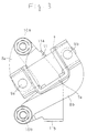
- the winding shaft 3 is adapted to be movable against a side plate 2a forming the shutter case 2, as shown in Figs. 2 - 7. More specifically, a bearing 7a is formed at the center of a bearing plate 7 forward and backward which is arranged on the side plate 2a in order to support the right and left ends of the winding shaft 3. A top end of a first link 8a and that of a second link 8b are swingably supported by one end of the bearing plate 7 adjacent to the shutter guide 30 and to the other end thereof away from the shutter guide 30 via pivots 9a and 9b, respectively.
- the first link 8a is swingably supported at the top end by one end of the bearing plate 7 adjacent to the shutter guide 30 as stated above and the base end by the side plate 2a of the shutter case 2 via a pivot 10a so as to project upward away from the shutter guide 30.
- the second link 8b which is swingably supported at the top end by the other end of the bearing plate 7 away from the shutter guide 30 as stated above and at the base end by the side plate 2a of the shutter case 2 via another pivot 10b so that the second link 8b extends under the winding shaft 3 toward the shutter guide 30 such as to bypass the winding shaft 3.
- a protecting link 11 intervenes between the base ends of both links 8a and 8b, and first and second stoppers 11a and 11b are formed in the protecting link 11 in order to control the swing range of the shaft plate 7.
- the pivots 10a and 10b are positioned so as to be accommodated within the diameter of the winding wheels 22 rotatably supported by the winding shaft 3.
- a collar 10c is also arranged to fit into and past the pivots 10a and 10b, thereby allowing the relative swinging of the first and second links 8a and 8b against the protecting link 11 even though bolts are tightly screwed. As illustrated in Fig.
- the protecting link 11 may be shaped to be as shown in Fig. 5, and also as shown in a second embodiment of Fig. 6 having the following construction.
- the base end of a protecting link 18 is integrally supported by the pivot 10a of the first link 8a, and an elongated hole 18a is formed at the top of the protecting link 18.
- a pin 8c at the top end of the second link 8b is movably fit into the elongated hole 18a, and thus, the pin 8c moves within the elongated hole 18a in accordance with the swinging of the second link 8b so as to abut against both ends of the elongated hole 18a, thereby controlling the swing range of the second link 8b.
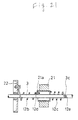
- the split-type balance spring 6 comprises first and second balance springs 6a and 6b as illustrated in Figs. 9 - 13. It is adapted to move together with a buffer spring 12 urged in the direction opposite to that in which the balance spring 6 is urged, to follow as closely as possible to the turning effect of the winding drum 4 produced by the weight of the shutter curtain 1 so as to considerably reduce the operation force of opening the shutter curtain 1. More specifically, the buffer spring 12 is firmly connected at one end to the winding wheel 22 and at the other end being free and having a hook 12a formed thereon. A projection 3a passing through the coil of the buffer spring 12 is formed in the winding shaft 3. When the shutter curtain 1 is fully open, the projection 3a is positioned suitably in the coil.
- the projection 3a advances toward the hook 12a through the coil until it is stopped by the hook 12a at the point where the shutter curtain 1 reaches a predetermined half-open position H 1 en route.
- the buffer spring 12 is arranged to be loaded as the winding drum 4 is rotated so as to open the shutter curtain 1 fully.
- the balance spring 6 is constructed such that the first balance spring 6a is firmly connected at one end to the winding wheel 22 and at the other end via a fastening tool 14 integrally to a retainer 13 rotatably freely supported by the winding shaft 3 and the second balance spring 6b is firmly connected at one end to the retainer 13 via another fastening tool 14 and at the other end to the winding shaft 3.
- An operating pin 15 projects from the retainer 13 toward the outer diameter of the winding drum 4 and has a top end which is movably fit into a guide groove 4a with some play arranged in the inner periphery of the winding drum 4.
- a stopper pin 16 is arranged in the guide groove 4a to stop the operating pin 15. The position of the operating pin 15 stopped by the stopper pin 16 is determined as follows.
- the operating pin 15 and the stopper pin 16 do not abut against each other so as to load the first and second balance springs 6a and 6b equally.
- the winding drum 4 is then rotated so as to raise the shutter curtain 1 so as to allow the first and second balance springs 6a and 6b to urge the winding drum 4 owing to the loading force in the direction in which the shutter curtain 1 is wound.
- the operating pin 15 formed in the retainer 13 is rotated relatively to the winding drum 4 in accordance with the restoring force of the torsion of the first and second springs 6a and 6b, and thus the pin 15 approaches the stopper pin 16.
- the operating pin 15 is adapted to abut against the stopper pin 16 at the half-open position H 2 lower than the foregoing half-open position H 1 .
- the restoring force of the torsion of the first balance spring 6a which is firmly connected at one end to the winding wheel 22 is controlled, and thus, the winding drum 4 is urged only by the loading force of the second balance spring 6b for further operation.
- the second balance spring 6b urges the winding drum 4 in the winding direction
- the buffer spring 12 urges the winding drum 4 in the balancing direction.
- the second balance spring 6b is loaded by urging the winding drum 4 and the buffer spring 12 restores the winding drum 4 by urging it in the rewinding direction.
- the buffer spring 12 is disengaged from the projection 3a, and for further operation, only the second spring 6b urges the winding drum 4.
- the loading force of the first balance spring 6a which is controlled to be restored, conforms with the loading force of the second spring 6b, whereby in a position lower than the half-open position H 2 , the operating pin 15 is disengaged from the stopper pin 16 and the first and second balance springs 6a and 6b are loaded by urging the winding drum 4 in the winding direction.
- the balance spring 6 constructed as stated above is adapted as follows.
- the torsion of the first and second balance springs 6a and 6b connected in series is restored by a half turn per one rotation of the winding drum 4 (where the first and second balance springs 6a and 6b have the same length), and consequently, the urging force is gradually decreased, as illustrated in Fig. 13.
- the urging force is sharply decreased.
- the overall urging force is adapted to follow as closely as possible to the turning effect of the winding drum 4 which changes in three stages in an opening and closing range of the shutter curtain 1 for adjustment of the turning effect as indicated by a curve shown in Fig. 13, that is, the load of the pulled-out portion of the shutter curtain 1.
- the balance spring 6 may be modified by the following construction as shown in a third embodiment of Figs. 14 - 17.
- a stopper pin 17 is integrally projected from the winding shaft 3, and the operating pin 15 is arranged on a retainer 13a. That is, the balance spring 6 is adapted as follows. In the fully-opened state of the shutter curtain 1, the second balance spring 6b urges the winding drum 4 in the winding direction, whereas the buffer spring 12 urges the winding drum 4 in the balancing direction. In this state, the winding drum 4 is rotated so as to lower the shutter curtain 1, and the second balance spring 6b is loaded by urging the winding drum 4 in the winding direction, while the buffer spring 12 restores the winding drum 4 by urging it in the unwinding direction.
- the buffer spring 12 is disengaged from the projection 3a, and for further operation, only the second balance spring 6b urges the winding drum 4.
- the loading force of the first balance spring 6a conforms with the loading force of the second balance spring 6b, whereby in a lowering position in excess of the half-open position H 2 , the operating pin 15 is disengaged from the stopper pin 17 and the first and second balance springs 6a and 6b are loaded by urging the winding drum 4 in the winding direction.
- Such a modified balance spring as well as the balance spring 6 of the first embodiment enables a well-balanced light operation of opening the shutter curtain 1.
- the former is superior to the latter in the following respects.
- the stopper pin 17 can be arranged on the winding shaft 3 having intrinsically greater strength, whereas the stopper pin in the first embodiment is arranged on the weaker winding drum 4.
- a winding drum for general purpose can be used for the former balance spring without upgrading the strength thereof.
- a retaining claw 13b for retaining the first and second balance springs 6a and 6b is formed in the retainer 13a, and thus, the operation of fitting the balance springs 6a and 6b can be simplified.
- the retainer 13 for interconnecting the split-type balance spring 6 may be modified not to include a retaining member, so that it does not fasten the first balance spring, as shown in the embodiments of Figs. 18 - 20.
- the balance spring 6 and the retainer 13c shown in the fourth embodiment of the Fig. 18 are modified as follows.
- a hook 6c at one end of the first balance spring 6a is retained and connected by a retaining claw 22a integrally formed on the winding wheel 22.
- Respective hooks 6c formed on the other end of the first balance spring 6a and one end of the second balance spring 6b are retained by a retaining claw 13d which faces toward the outer diameter and is arranged in the retainer 13c.
- Another hook 6c at the other end of the second balance spring 6b is retained by a retaining claw 19a formed on a fixing member 19.
- the fixing member 19 is screwed to the winding shaft 3 by way of a vis in this type of balance spring by the following construction.
- the hooks 6c of the balance spring 6 retained by the retaining claws 22a, 13d and 19a are bent with folds in order to produce some play.
- vis holes 19b and 3b are positioned not to match each other, they can be easily matched without forcing the fixing member 19 into rotating against the urging force of the first and second balance springs 6a and 6b.
- the balance spring and the retainer shown in a fifth embodiment of Fig. 19 may be modified as follows.
- a screw 13f is engraved around the outer periphery of the retainer 13e, and respective ends of the cut coil-type first and second balance springs 6a and 6b are turned into the screw 13f.
- screws 22b and 19d similar to the screw 13f are formed on a spring-connecting portion of the winding wheel 22 and a spring-connecting portion of the fixing member 19c, respectively, thereby turning the other ends of the first and second balance springs 6a and 6b into the screws 22b and 19d.
- These screws 13f, 22b and 19d are tapered such that the further the first and second balance springs 6a and 6b are turned thereinto, the more firmly they are tightened.
- the operation of turning the balance springs into the screws is as follows.
- the one end of the first balance spring 6a is first turned into the screw 22b of the winding wheel 22, and then, the other end of the first balance spring 6a is turned into one end of the screw 13f of the retainer 13e.
- the one end of the second balance spring 6b is turned into the other end of the screw 13f, and lastly, the other end of the second balance spring 6b is turned into the screw 19d of the fixing member 19c.
- the fixing member 19c is connected to the winding shaft 3 by way of a vis.
- the balance springs may be turned into the screws by the following operation.
- the fixing member 19c is fastened to the winding shaft 3 and the balance springs 6a and 6b are loosely turned into the screws 13f, 22b and 19d. In this state, either of the winding shaft 3 or the winding wheel 22 is rotated, thereby turning the balance springs 6a and 6b into the screws firmly.
- the latter operation offers the following advantage.
- the vis holes 3b and 19b provided for the winding shaft 3 and the fixing member 19c, respectively are displaced from the correct positions, they can be matched by adjusting the amount the respective screws are tightened.
- the balance spring and the retainer may be modified as illustrated in a sixth embodiment of Fig. 20 by the following construction.
- a bracket 20 having an engaging hole 20a is provided for a retainer 13g in order to engage with hooks 6d formed in the first and second balance springs 6a and 6b.
- Other engaging holes 22c and 19f are also provided for the winding wheel 22 and the fixing member 19e, respectively.
- the balance springs 6a and 6b, the retainer 13g, the winding wheel 22 and the fixing member 19e are serially connected to each other by the engagement of the hooks 6d with the engaging holes 20a, 22c and 19f.
- the vis holes 3b and 19b provided with the winding shaft 3 and the fixing member 19e, respectively can be positioned to match each other owing to some play produced by bending the hooks 6d with folds.
- the balance spring 6 having a desired urging force can be obtained by variously selecting and combining standardized balance springs having a predetermined urging force. Consequently, it is not necessary to take the trouble of preparing a spring having an urging force in correspondence with the weight of the shutter curtain, thus enabling a decrease in the number of parts.
- the buffer spring 12 for absorbing the impact when the shutter curtain is fully opened.
- the buffer spring 12 is not limited to that shown in the first embodiment, but may be a split-type provided with a weight of inertia 21 as shown in a seventh embodiment of Figs. 21 and 22.
- the buffer spring 12 can be adapted to absorb the impact by a loading force in correspondence with the raising speed of the shutter curtain 1. That is, the buffer spring 12 comprises first and second buffer springs 12b and 12c, and a weight of inertia 21 intervening therebetween is rotatably freely supported by the winding shaft 3.
- the first buffer spring 12b is firmly supported at one end by the winding wheel 22 and forms a retaining hook 12d at the other end.
- the second buffer spring 12c is firmly supported at one end by the weight of inertia 21 and forms a hook 12e at the other end, retained by a projection 3c arranged on the winding shaft 3.
- the winding wheel 22 and the winding shaft 3 are relatively rotated with each other in correspondence with the rotation of the winding wheel 22.
- a retaining claw 21a arranged on the weight of inertia 21 moves through the coil of the first buffer spring 12b toward the winding drum 4.
- the retaining claw 21a is adapted not to contact the winding drum 4 even when the shutter curtain 1 is fully closed.
- the retaining claw 21a gradually moves through the coil of the first buffer spring 12b toward the retaining hook 12d so as to be stopped by the retaining hook 12d when the shutter curtain 1 is raised to some degree.
- the buffer spring 12 is wound so as to be gradually loaded, thereby resisting the force of raising the shutter curtain 1, and exerting a buffering effect.
- the weight of inertia 21 is rotated such as to follow the first buffer spring 12b, being susceptible to the turning effect caused by the winding of the first buffer spring 12b, thereby further winding the second buffer spring 12c.
- the loading forces of both the buffer springs 12b and 12c are applied to the shutter curtain 1, the raising speed of which can be buffered.
- the first buffer spring 12b is rapidly wound on.
- the weight of inertia 21 does not rotate at a greater speed in correspondence with the rapidly increasing turning effect of the first buffer spring 12b, but instead, it is as if it were firmly connected.
- the first buffer spring 12b is nearly loaded so as to gradually narrow the winding diameter and to be wound firmly on the winding shaft 3, thereby controlling the rotation of the winding wheel 22.
- Such a controlled state of the winding wheel 22 can be gradually released by the following operation.
- the turning effect of the loaded first buffer spring 12b is applied to the weight of inertia 21, which is rotated by loading the second buffer spring 12c.
- the use of the buffer spring 12 which is set to exert a smaller buffering effect in correspondence with the slower speed of raising the shutter curtain 1 also enables the reliable absorption of the impact caused by raising the shutter curtain 1 at a greater speed. As a result, the shutter curtain 1 can be fully opened quietly, free from impact, being influenced very little by the raising speed.
- the buffer spring 12 provided with the weight of inertia 21 may be modified as shown in an eighth embodiment of Fig. 23. More specifically, the buffer spring 12 is constructed in a manner similar to that of the seventh embodiment such that the buffer spring 12 fitted between the winding wheel 22 and winding shaft 3 comprises first and second buffer springs 12f and 12g, and a weight of inertia 21b intervenes therebetween.
- the first buffer spring 12f further includes a greater coil 12h and a smaller coil 12i having opposite winding directions, and a retaining portion 12j is also formed between both the coils 12h and 12i.
- a claw 22e formed on the winding wheel 22 is adapted to move through the greater coil 12h.
- the buffer spring 12 can exert a buffering effect in a manner similar to that of the seventh embodiment.
- the winding drum 4 rotatably supported by the winding shaft 3 will now be explained.
- the shutter curtain 1 is integrally interconnected at one end to the winding drum 4.
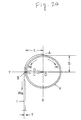
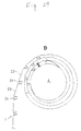
- the winding drum 4 is generally shaped to have a complete circular section, but may be shaped to have an elliptic section as shown in a ninth embodiment of Figs. 24 - 26.
- the use of the winding drum 4 having an elliptic section as well as the use of the split-type balance spring 6 enables a light operation of opening the shutter curtain 1.
- the position A for connecting the winding drum 4 to the shutter curtain 1 is determined to be substantially at the top of the winding wheel 22 when the shutter curtain 1 is fully closed.
- the wheel diameter is determined to have the smaller diameter X passing through the position A for connecting the shutter curtain 1 and the greater diameter Y passing through the position turned at substantially 90 degrees from the position A, that is, the position B for pulling out the shutter curtain 1 from the winding drum 4 when the shutter curtain 1 is fully closed (when the radiuses of the greater and smaller diameters are indicated by L and S, respectively, L>S).
- the rotation moment due to the weight of the shutter curtain 1 is indicated as M, the rotation moment due to a loading force of the balance spring 6 as m, the weight of the pulled-out portion of the shutter curtain 1 as Wa, the thickness of the shutter curtain 1 as T, the winding diameter of the shutter curtain 1 (distance from the central position O to the pulled-out position B of the winding drum 4) as C, and the radius of the winding drum 4 at the pulling-out position B as D.
- the winding diameter C is substantially expressed by the total of the radius D of the winding drum 4 and the length T/2 equivalent to one half the thickness of the shutter curtain 1, (C ⁇ D+T/2).
- the rotation moment M caused by the shutter curtain 1 can be obtained by the product of the weight Wa of the pulled-out portion of the shutter curtain 1 and the winding diameter C [M ⁇ Wa x (D+T/2)].
- the rotation moment M due to the loading force of the balance spring 26 decreases linearly in proportion to the rotation amount of the winding drum 4.
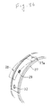
- the rotation moment M due to the weight of the shutter curtain 1 varies in accordance with a decrease of the radius D of the winding drum 4 at the pulled-out position B from the radius L of the greater diameter and the radius S of the smaller diameter, together with a decrease of the weight of the shutter curtain 1, thereby decreasing the rotation moment M due to the shutter curtain 1 as shown in the curve having the shape of a projection as viewed from under the straight line of the rotation moment m, as illustrated in Fig. 26.
- the rotating moment M is smaller than the rotating moment m (M ⁇ m).
- the shutter curtain 1 starts on a second rotation when the winding drum 4 is at 3/4 rotation; the winding diameter C gradually increases ( C ⁇ D+3T/2 at 3/4 rotation), and accordingly, the rotation moment M due to the shutter curtain 1 becomes greater than the rotation moment m due to the balance spring 6.
- the diameter D of the winding drum 4 coincides with the radius S of the smaller diameter, thereby controlling an increase in the winding diameter C.
- the rotation moment M can be prevented from being considerably greater than the rotation moment m.
- the rotation moment M due to the shutter curtain 1 and the rotation moment m due to the urging force of the balance spring 6 are substantially balanced.
- the rotation moment m due to the loading force of the balance spring 6 acting upon the winding drum 4 in the winding direction is more influential than the rotation moment M due to the weight of the pulled-out shutter curtain 1 acting upon the winding drum 4 in the unwinding direction, thereby raising the shutter curtain 1 easily as desired.
- the operational force required immediately after raising the shutter curtain 1 from the fully-closed state can be reduced, and for further operation, the shutter curtain 1 can be raised smoothly due to the inertia. As a result, the shutter curtain 1 can be operated with little force for opening.
- the winding diameter considerably changes because of an increase or decrease of the winding amount.
- the winding drum 4 is elliptically shaped, the diameter passing through the position for pulling out the shutter curtain 1 coincides with the smaller diameter, thus controlling the change of the winding diameter.
- the rotation moment M due to the shutter curtain 1 changes as linearly as possible.
- the winding drum is not limited to an elliptic section, but may be ovaloidal. Further, a non-complete circular shaped winding drum having a greater diameter coinciding with the diameter passing through the position for pulling out the shutter curtain 1 from the winding drum 4 in the fully-closed state effectively reduces the operating force required immediately after raising the shutter curtain 1 from the fully-closed state.
- a suitable value of the difference between the greater diameter and the smaller diameter of the winding drum is not limited to the difference shown in the drawings, but may be determined according to various conditions such as the thickness and weight of the shutter curtain 1, the diameter of the winding drum, and the like.
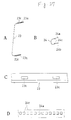
- the shutter curtain 1 shown in the first embodiment is constructed by integrally interconnecting a main slat 23 having rigidity to a subsidiary slat 24 having flexibility so as to be deformed elastically. Due to elastic deformation of the subsidiary slat 24, the shutter curtain 1 can be deformed to either configuration of being wound on the winding drum 4 or of closing the opening portion. More specifically, as illustrated in Figs. 27 - 29, the main slat 23 is generally formed in a U-shape such as to slant upward gradiently toward the top by means of suitable forming, such as mold forming and roll forming.
- fitting grooves 23a and 23b bent outward with folds are formed on leg portions (as a matter of convenience, assuming that the shutter curtain 1 is moved vertically, the upper and lower fitting grooves are numbered as 23a and 23b, respectively, but the shutter curtain 1 may be used for a symmetrical-opening type for opening and closing both to the right and left directions and for a horizontal-opening type for opening and closing horizontally).
- Engaging holes 23c are further provided outside of the fitting grooves 23a and 23b.
- the subsidiary slat 24 is also generally formed in a U-shape such as to slant upward gradiently toward the top.
- Leg portions 24a and 24b further form engaging pieces 24c having the top ends toward the opposite side of the leg portions and projecting facing opposite to each other from both the leg portions.
- the main slats 23 and the subsidiary slats 24 are serially connected by fitting the lower leg portion 24b of the subsidiary slat 24 into the upper fitting groove 23a of the main slat 23 so as to form the shutter curtain 1 having a round pattern as illustrated in Fig. 29D.
- this type of shutter curtain 1 is free from a gap in a connecting portion between slats, thus effectively avoiding the noise caused by the operation of opening and closing or the wind due to the abutment of slats. Hence, a quiet and low-noise shutter used for buildings can be obtained.
- This type of shutter also has good properties such as being flame-proof, fume-tight and sound insulating since no gaps are present in the connecting portions between slats.
- the shutter curtain 1 may employ a general-use type obtained by interlock-connecting rigid slats.
- the shutter curtain constructed by combining the rigid main slat 23 and the elastic subsidiary slat 24 may include the shutter curtain disclosed in France Patent No. 2664937.
- the shutter curtains having the patterns shown in Figs. 29A, 29B and 29C, respectively, may also be used.
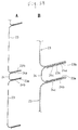
- the shutter curtain 1 may be constructed of single thin-plate-like slat main members 1a having flexibility so as to freely bend and slat skeleton members 1b having rigidity.
- Such patterns are shown in Figs. 30 - 33 in which the slat skeleton members are fastened to one side of the slat main members 1a at predetermined spacing in parallel to each other by utilizing thermosetting adhesives or fastening members such as rivets or the like.
- the slat skeleton members 1b may be modified as follows. As shown in Fig.
- the slat skeleton members 1b generally formed in a U-shape (bending-form) are fastened at the flat side to the main slat member 1a.
- the leg portions of the slat skeleton members 1b are fastened to the slat main members 1a, or the tubular slat skeleton members 1b are fastened to the slat main members 1a.
- the adjacent slat skeleton members 1b are overlapped, as shown in Fig. 32.
- the slat skeleton members 1b may be modified as illustrated in Fig.
- the shutter curtain 1 can be produced by using the slat main members 1a on which pictures are drawn in advance. Also, a buffer member may adhere to the slat skeleton members 1b in order to protect them from being scratched.
- the shutter curtain 1 can be produced simply by fastening the slat skeleton members 1b to the slat main members 1a by means of adhering, or the like, equipment for producing the shutter curtain 1 can be simple, thereby enhancing operational and economical performances.
- the overlapped-type shutter curtain 1 shown in Fig. 32 has the advantages of improving heat-insulation and flame-proof properties in case of fire. Some of these types of shutter curtains can be further prevented from collapsing, which might be caused by the engagement of the slat skeleton members 1b due to the damage (by burning) of the slat main members 1a in case of fire, thus producing even better flame-proof properties.
- the shutter curtain 1 produced by successively varying the spacing between the slat skeleton members, the length, or the thickness thereof offers the following advantages.
- the shutter curtain 1 When the shutter curtain 1 is wound on the drum as shown in the pattern in Fig. 33D, it can be configured as closely as possible to a spiral shape.
- the slat main members 1a cannot be forcibly bent, thereby effectively avoiding the resulting folds for the slat main members 1a.
- the slat main members formed of a transparent or translucent material can be used as a daylight shutter.
- the slat main members can also be formed of various materials, such as a flexible-thin metal plate, for example, a spring steel plate, a synthetic resin film, narrow woven materials.
- the fastening means of the slat main members and the skeleton members is not limited to adhering, but may employ suitable means such as welding, vis fastening, or the like, when necessary.
- the shutter curtain 1 produced by overlapping the slat skeleton members 1b as shown in an eleventh embodiment of Fig. 34 may be constructed such that an incombustible foaming member 26 which is thermally foamed intervenes between the slat main member 1a and the slat skeleton member 1b.
- foaming member 26 which is thermally foamed intervenes between the slat main member 1a and the slat skeleton member 1b.
- the shutter curtain 1 is usually thin so as to have a smaller winding diameter.
- a thick heat insulating layer between the slat main member 1a and skeleton member 1b is formed by foaming the foaming member 26, thus effectively obtaining good heat insulating properties.
- the protecting pad 28 is constructed such that it comprises a surface slanting 28a gradiently upward toward the hanging member 1c in the unwinding direction of the shutter curtain 1 and a difference in level 28b adjacent to the hanging member 1c.
- the shutter curtain 1 can be wound a second rotation without being damaged.
- the protecting band 27 and the protecting pad 28 can be integrally attached to a desired position by selectively and disengageably engaging a snap-receiving hole 29a disposed on the inner surface of the protecting pad 28 with one of the projecting snaps 29 arranged on the outer surface of the protecting band 27 at predetermined spacing.
- a cut 31 generally formed in a U-shape is further disposed surrounding the snap 29 in order to easily relieve the unused snaps which do not engage with the snap-receiving hole 29a.
- the remaining side of the U-shaped cut 31 may be further perforated so that the snaps can be cut more easily. Or there may even be no need to form the cuts 31 or the like, if the snaps 29 are formed the projections to such a degree that they are not in the way of winding the shutter curtain 1.
- fixing holes 32 for receiving the hanging members 1c are circumferentially provided at predetermined spacing for the protecting band 27. Therefore, no matter from which direction the protecting pad 28 is attached, the hanging members facing opposite to each other are not engaged therewith owing to the difference in level 28b.
- the protecting band 27 and the protecting pad 28 may be modified as follows.
- a recess groove 27a the width of which is equivalent to that of the protecting pad 28 is circumferentially formed on the outer surface of the protecting band 27, and the snap 29 is arranged not to project from the recess groove 27a.
- the protecting pad 28 attached to the protecting band 27 via a snap can be supported at both ends by the recess groove 27a.
- the protecting pad 28 can be reliably precluded from displacement caused by rotating around the position for receiving the snap, which might be caused by a vibration in winding the shutter curtain 1 on and off, and, what is more, it is not necessary to cut the unused snaps 29.
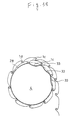
- recesses 33 corresponding to the shape of the slats of the shutter curtain 1 can be disposed on the outer surface of the winding drum 4.
- the bending portions of the hanging members 1c (or the slats) are adapted to fit into the recesses 33 in the unwound state of the shutter curtain 1, as illustrated in Fig. 39, thereby adjusting the winding diameter of the shutter curtain 1.
- the plurality of recesses 33 are formed such as to be successively shallower, the winding diameter can be adjusted even more properly, thus avoiding a sudden increase in the winding diameter.
- the shutter curtain 1 is wound on such that the interlock-connecting portion 1d abuts between the neighboring recesses 33. Hence, the recesses 33 are not directly dependent on the winding of the shutter curtain 1.
- a securing portion 2b is formed at the rear edge of the side wall 2a, and secured to the body of the building by utilizing bonding members (not shown) such as nails or the like.
- Temporary retaining projections 2c are further formed on the top and bottom ends of the securing portion 2b such as to bypass holes 2d for receiving the bonding members and to avoid interference with the winding of the shutter curtain 1.
- the temporary retaining projections 2c are cut and raised in such a way that they comprise sharp top edges 2e and bending portions 2f for not allowing the top edges 2e to prevent the securing portion 2b from abutting against the body.
- the side walls 2a Prior to securing the side walls 2a to the body by driving the bonding members, the side walls 2a can be temporarily retained by driving the temporarily projections 2c into the body. Subsequently, the side walls 2a are screwed to the body via bonding members by a tool, thus completing the securing operation. That is, since the side walls 2a can be temporarily retained without requiring a difficult operation such as driving the bonding members while supporting the side walls 2a, a bracket securing operation can be performed extremely easily and safely, which is conventionally performed while holding the side walls 2a, bonding members and a tool in both hands at a high place. As a result, operational performance and safety in accordance with the operation of securing the side walls 2a can be remarkably enhanced, and also the operation of positioning the side walls 2a can be simplified.
- the temporary retaining means for temporarily retaining the side walls 2a may be constructed such that the temporary retaining projections 2c are formed on the upper and lower edges of the securing portion 2b or on the top and bottom edges of the securing portion 2b, as shown in Figs. 41 - 43.
- the shutter case 2 is constructed as follows. First and second case angles 34 and 35 are arranged on the upper portion of the respective right and left side walls 2a secured to the body as stated above such that the case angles 34 and 35 are positioned on a portion adjacent to the body (hereinafter referred to as the body side) and a portion adjacent to the exterior (hereinafter referred to the exterior side), respectively. Also, inner and outer lintel frames 36 and 37 positioned on the lintel of the lower portion of the side wall 2a and five angle frame members for a third case angle 38 positioned on the exterior side of the lower portion of the side wall 2a are disposed so as to frame these case angles 34, 35, 36, 37 and 38 with plates 39, 40 and 41. Thus, the shutter case 2 is assembled.
- the top, bottom and front portions of the shutter case 2 are covered with the top case plate 39 supported between the first and second case angles 34 and 35, the front case plate 40 supported between the second and third case angles 35 and 38, and the bottom case plate 41 supported between the third case angle 38 and the outer lintel frame 37.
- the construction of the respective case plates 39, 40 and 41 for assembly is as follows.
- the first case angle 34 is formed as a hollow having a generally quadrilateral section by such means as roll-forming a band-like steel plate (the remaining angles are formed in a similar manner). It has an opening 34a at the front top portion and a surface which will be attached to the body 34b projecting upward adjacent to the interior.
- the second case angle 35 comprises a slant surface 35a gradiently slanted toward the front, a supporting surface 35b arranged above the slant surface 35a, which is bent toward the interior, the top end of which is bent upward so as to generally form in a V-shape, and another supporting surface 35c arranged below the slant surface 35a, which is bent downward, the top end of which is bent toward the front so as to generally form a V-shape.
- the third case angle 38 is also shaped in a manner similar to the second case angle 35.
- the outer lintel frame 37 is formed as a hollow having a generally quadrilateral section and has an opening 37a at the front bottom portion.
- the outer lintel frame 36 is generally formed in an L-shape.
- fixing plates 42 and 43 are integrally attached to the exterior sides of the slant plates 35a and 38a of the second and third case angles, respectively.
- These fixing plates 42 and 43 have crank-shaped first retaining portions 42a and 43a at one end and second retaining portions 42b and 43b bent in an R-shaped, respectively, at the other end.
- the top case plate 39 is formed of a bending portion 39a adjacent to the interior, the end close to the body of which is bent downward so as to generally form in an L-shape, and another bending portion 39b adjacent to the exterior, the end close to the exterior of which is bent downward and the top end of which is further bent forward so as to form in a crank-shape as viewed from the side of the shutter case 2.
- the front case plate 40 includes a crank-shaped upper bending portion 40a and a lower bending portion 40b at the top and bottom ends.
- the bottom case plate 41 comprises a crank-shaped bending portion 41a adjacent to the exterior at one end close to the exterior, and a bending portion 41b adjacent to the interior, which is bent upward so as to generally form in an L-shape, at the other end close to the interior.
- the top case plate 39 is temporarily supported between both the angles 34 and 35 such that the bending portion 39a adjacent to the interior is inserted from the opening 34a of the first case angle 34 and the other bending portion 39b adjacent to the exterior is laid on the supporting surface 35b of the second case angle 35.
- the front case plate 40 is formed such that the upper bending portion 40a is retained by the supporting surface 35c of the second case angle 35 and the lower bending portion 40b is retained by the upper supporting surface 38b of the third case angle 38.
- a corner member 44 both ends of which are bent so as to generally form in a U-shape is forced into the fixing plate 42 from the outside, thereby abutting and supporting the top end of the bending portion 39b adjacent to the exterior of the top case plate 39 and the upper end of the front case plate 40 against each other so as to be fastened.
- the lower end of the front case plate 40 and the end adjacent to the exterior of the bottom case plate 41 are supported and fastened by a corner member 45.
- the end adjacent to the interior of the bottom case plate 41 is supported by inserting the bending portion 41b close to the interior into the outer lintel frame 37 in a manner similar to the top case plate 39.
- the shutter case 2 may be modified by the following constructions.
- the second and third case angles 35 and 38 are shaped as shown in Fig. 47, and the corner members 44 and 45 are pushed from the outside to the case angles 35 and 38, respectively.
- the corner members 44 and 45 detachable from the case angles 35 and 38 are formed in various shapes, and they are freely changed as desired.
- the latter modification has the advantage of freely changing the design of the shutter case 2.
- the top case plate 39 is mounted on the first and second case angles 34 and 35 arranged adjacent to the interior and exterior and the bottom case plate 41 is mounted on the outer lintel frame 37 and the third case angle 38 arranged adjacent to the interior and exterior.
- the bending portion 39a adjacent to the interior is inserted from the opening 34a disposed on the first case angle 34 so as to move freely forward and backward (along the interior and exterior dimension). Consequently, even though the fitting surface of the body is uneven, the shutter case 2 can be secured to the body by moving and adjusting the first case angle 34 forward and backward relative to the shutter case 2, thereby remarkably improving the degree of freedom for attaching the shutter case 2, and further enhancing the operational performance.
- Tapping screws are not employed for the case plates 39, 40 and 41 to be mounted on the case angles 34, 35, 37 and 38; but instead, the bending portions of the case plates are simply inserted into the openings so as to be freely moved forward and backward and adjusted and the other bending portions are laid on the case angles in order to support the case plates. Then, the corner members 44 and 45 are pushed into the case angles 35 and 38. Therefore, vis holes are not necessary, thus effectively avoiding the acceleration of corrosion which might be created therefrom and the advance of rain into the cases. This further improves the protection of the shutter case 2 and also enhances the durability of the winding drum 4, the shutter curtain 1 and a driving device such as a motor (not shown), or the like, against rain.
- a driving device such as a motor (not shown), or the like
- Side covers 46 cover the right and left side walls 2a from outside in which top, front and bottom case plates 39, 40 and 41 are assembled and supported, thus completing the assembly of the shutter case 2.
- the side covers 46 each comprise a side cover body 46a covering the side wall 2a and corner covers 46b covering the corner members 44 and 45, respectively.
- the corner covers 46b are fit into two portions having a different level 46c formed on the side cover body 46a in advance, thus firmly connecting the corner covers 46b to the side cover body 46a. Subsequently, a bottom surface 46d of the side cover body 46a is screwed into the bottom surface of the side wall 2a.
- the corner covers 46b of the side cover 46 are formed of hard plastics or a light alloy, and can be decorative from an aesthetic point of view by varying the colors.
- the arrangement of the side cover 46 prevents the right and left ends of the respective case plates 39, 40 and 41 from being directly exposed to the outside, thereby further improving the anticorrosiveness.
- the shutter guides 30 arranged on the lintel portions of the shutter case 2 will now be explained.
- the shutter guides 30 arranged on either side of the shutter case 2 each generally have a flare section so as to open gradiently upward.
- a pair of guide portions 30a are integrally formed on the upper end of the shutter guide 30 so as to guide the shutter curtain 1 pulled out from the winding drum 4.
- a insertion guide 47 is integrally formed on the lower end of the shutter guide 30 such that the lower portion is open so as to be formed in a recess groove and the backward portion of the groove on the upper portion leading to the guide portions 30a, thereby enabling the insertion of the upper end of the guide rail 5 from the inlet of the lower portion of the insertion guide 47.
- the groove portions forming the groove along a front and rear dimension is determined such that the width of inlet portions 47a positioned on the inlet side is substantially equivalent, or slightly wider than the width J of the guide rail 5, and that the width K of backward portions 47b positioned on the backward groove side is greater than the width J of the guide rail 5 (J ⁇ K).
- the insertion guide 47 is formed in an ant's nest shape, and the upper end of the guide rail 5 can be inserted obliquely along a front and rear dimension, preventing the corner portion on the upper end of the guide rail 5 from being caught by the groove portion.
- the guide rail 5 the upper end of which is inserted is raised vertically so that it can be inserted into the insertion guide 47, being positioned by the inlet portions 47a forming a narrow width therebetween. Also, a guide surface 5a of the guide rail 5 and the guide portions 30a of the shutter guide 30 precisely match each other, thereby communicating therewith and further improving the opening and closing of the shutter curtain 1 remarkably.
- the shutter guides 30 are formed of a resin material so as to prevent the damage of the shutter curtain 1.
- the shutter guides 30 each comprise the guide portions 30a, retaining portions 30b bending outward from the bottom end of the guide portions 30a and extending along groove bottom surfaces 47c of the insertion guide 47, spanning portions 30c which project from the bottom end of the guide portions 30a to the insertion guide 47 such as to have gradually greater width facing the insertion guide 47 and which span the guide rail guiding surface 5a and the guide portions 30a of the shutter guide 30.
- the guide rail 5 is made shorter in order to compensate for various possible errors, and thus a troublesome cutting operation of the guide rails is not necessary where the shutter curtain is opened and closed.
- a shutter guide when a gap having a different level is produced between the guiding surface 5a and the guide portions 30a, it is spanned with the spanning portion 30c as if it were a bridge, thereby avoiding a projection, such as an interconnecting portion for interconnecting two slats, from being inserted into the gap.
- retaining portions 30d for retaining the shutter guide 30 and retaining projections 30e are formed on the guide portions 30a and the retaining portions 30b, respectively.
- Reinforcing ribs 30f are also each arranged at the corner between the retaining portion 30b and the spanning portion 30c.
- the insertion guide 47 for receiving the upper end of the guide rail 5 is formed in an ant's nest shape so as to make the width between the backward portions 47b greater than that between the inlet portions 47a, thereby enabling the oblique insertion of the guide rail 5.
- the middle posts 48 can be simply attached and detached, and also be easily and precisely positioned.
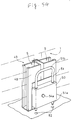
- a locking device 49 is constructed such that both legs 51a of a U-shaped drop rod 51 are slidably upward and downward inserted into an accommodating case 50 arranged on the interior side at the bottom of the middle post forming the guide rails 5 on either side.
- a handle 51b of the drop rod 51 is pushed and pulled, thereby disengageably fitting the top ends of the legs 51a of the drop rod 51 into engaging holes 52 disposed on the surface for placing the shutter.
- the locking device 49 can be locked and unlocked.
- a coil spring 53 urging the drop rod 51 is connected at one end swingably via a pin 54b to one side of a pivotable plate 54 which is pivotally supported by the accommodating case 50 via a pin pivot 54a and at the other end integrally to the bottom of the accommodating case 50.
- the leg 51a of the drop rod 51 is swingably arranged on the other side of the pivotable plate 54 via a pin 54c, thereby pivoting the pivotable plate 54 around the pin pivot 54a in accordance with the upper and lower motion of the drop rod leg 51a.
- the coil spring 53 is positioned on one side away from the leg 51a, thereby urging the drop rod 51 in the unlocking direction (upward).
- the coil spring 53 displaces from the one side away from the leg 51a to the other side adjacent thereto, passing over the pin pivot 54a, thereby urging the drop rod 51 in the locking direction (downward). That is, the coil spring 53 is adapted to change the urging directions of the drop rod by passing over the pivot.
- the drop rod legs 51a can be firmly engaged with the engaging holes 52, and even when the middle post 48 is vibrated, being subjected to a strong wind, the legs 51a are firmly connected to the surface for placing the shutter without pulling the legs 51a out of the engaging holes 52.
- an unlocked state can be securely maintained. Further, the locking and unlocking operations can be performed rapidly, lightly and securely.
- the locking device 46 may be constructed as shown in fifteenth and sixteenth embodiments of Fig. 56. No matter how it is constructed, in a locked state, legs 48a of a drop rod 48 are urged in the locking direction by a coil spring 51, whereas in an unlocked state, they are urged in the unlocking direction by the coil spring 51.
- the bearing plate 7 in the fully-open state of the shutter curtain 1, the bearing plate 7 is fully open, being controlled by the second stopper 11b, and separate from the shutter guide 30.
- the winding diameter of the shutter curtain 1 is greater, and thus, the shutter curtain 1 is substantially perpendicular to the shutter guide 30.
- the rotation moment M due to the weight of the pulled-out portion of the shutter curtain 1 is exerted on the bearing plate 7, thereby swinging the links 8a and 8b toward the shutter guide 30 and further gradually shifting the bearing plate 7 toward the shutter guide 30.
- the shutter of the embodiment according to the present invention is simply constructed such that a pair of right and left bearing plates 7 are each swingably supported by the links 8a and 8b.
- a quick response can be made to the imbalance of the force exerted on the bearing plate 7 whereby the links 8a and 8b swing so as to move the bearing plate 7. More specifically, when the shutter curtain 1 is pulled out so as to make the winding diameter smaller, the winding shaft moves toward the shutter guide 30, while the shutter curtain 1 is wound on; the winding shaft 3 gradually moves away from the shutter guide 30, thus maintaining the position of the shutter curtain 1 facing the shutter guide 30 below.
- the noise and the damage due to a shock caused by abutting the shutter curtain 1 against the shutter guide 30 can be minimized.
- both the first and second links 8a and 8b for swinging the bearing plate 7 are adapted to be accommodated within the diameter of the winding wheel 22.
- first and second links project upward outer-circumferentially from a winding wheel, but instead, the space for the links 8a and 8b can be guaranteed within the diameter of the winding wheel 22.
- the space for accommodating the links 8a and 8b can be reduced as small as possible, further enabling the downsizing of the shutter case 2.
- the stoppers 11a and 11b are arranged on the protecting link 11, thus reliably preventing the swinging link mechanism from passing over the change point (the dead point) and from being in the unreturnable position.
- the protecting link 11 also serves the function of strengthening the side wall 2a, thereby increasing the strength of the shutter. It goes without saying that the stoppers may be arranged adjacent to the body.
- the winding shaft moves forward and backward on the basis of the winding diameter which varies in accordance with the winding and rewinding of the shutter curtain.
- the position of the shutter curtain can be maintained such as to face the shutter guide below, thereby preventing the shutter curtain from abutting against the shutter guide and minimizing the noise and the damage due to shock.
- the arrangement of the links for swinging the bearing plate is as follows.
- the first link is pivoted at one end to one end of the bearing plate, adjacent to the shutter guide, and at the base end swingably to the body side so as to project upward away from the shutter guide
- the second link is pivoted at one end to the other end of the bearing plate, away from the shutter guide and at the base end swingably to the body side so that the second link extends under the winding shaft toward the shutter guide such as to bypass the winding shaft.
- first and second links project upward outer-circumferentially from a winding wheel
- the space for the links can be guaranteed within the diameter of the winding wheel.
- the space for accommodating the links can be reduced as small as possible, thus further enabling the downsizing of the shutter case.
- the protecting link disposed between the base ends of both the links in which the stoppers are further arranged reliably prevents a swinging link mechanism from passing over the change point and from being in the unreturnable position.
- the protecting link also serves the function of strengthening the body side pivotally supporting both the links, thereby increasing the strength of the shutter.
Landscapes
- Engineering & Computer Science (AREA)
- Structural Engineering (AREA)
- Architecture (AREA)
- Civil Engineering (AREA)
- Operating, Guiding And Securing Of Roll- Type Closing Members (AREA)
Claims (2)
- Einrichtung zum Verlagern der Wickelwelle (3) eines einem Gebäude zuzuordnenden Rolladens,
die eine rechteckige Lagerplatte (7) mit erstem und zweitem Ende und zur Lagerung der Wickelwelle (3) aufweist sowie eine Laschenanordnung mit einer ersten und einer zweiten Lasche in der Zuordnung zum einen bzw. anderen Ende der Lagerplatte zum Verstellen der Lagerplatte (7) in der Form einer schwingenden Bewegung nach vorn und nach hinten, um die Wickelwelle abhängig vom Wickeldurchmesser des Rolladens zu verstellen,
dadurch gekennzeichnet, daß ein erstes Ende der ersten Lasche (8a) drehbar mit dem ersten Ende der Lagerplatte verbunden ist und daß diese erste Lasche (8a) nach oben und außen gerichtet ist, um ein zweites Ende der ersten Lasche mit einem ersten Basiszapfen (10a) nahe dem Gebäude zu verbinden, und daß ein erstes Ende der zweiten Lasche (8b) mit dem zweiten Ende der Lagerplatte verbunden und so bogenförmig ist, daß es sich nach unten und um die Wickelwelle herum erstreckt, um ein zweites Ende der zweiten Lasche mit einem zweiten Basiszapfen (10b) zu verbinden, der nahe dem Gebäude angeordnet ist, wobei die Zuordnung der Laschenanordnung es ermöglicht, daß die Laschen innerhalb des Querschnittbereiches der Wickeltrommel (4) bleiben. - Einrichtung gemäß Anspruch 1, gekennzeichnet durch eine Schutzlasche (11) zwischen den zweiten Enden der ersten und der zweiten Lasche und einen Anschlag (11a, 11b) in der Zuordnung zur Schutzlasche zur Bestimmung des Bereiches der schwingenden Bewegung der Lagerplatte.
Priority Applications (3)
| Application Number | Priority Date | Filing Date | Title |
|---|---|---|---|
| EP93306213A EP0651127B1 (de) | 1993-08-05 | 1993-08-05 | Einrichtung zum Verlagern der Wickelwelle eines Ladens eines Gebäudes |
| DE1993611905 DE69311905T2 (de) | 1993-08-05 | 1993-08-05 | Einrichtung zum Verlagern der Wickelwelle eines Ladens eines Gebäudes |
| US08/102,389 US5460216A (en) | 1993-08-05 | 1993-08-05 | Device for moving a winding shaft in a building shutter |
Applications Claiming Priority (2)
| Application Number | Priority Date | Filing Date | Title |
|---|---|---|---|
| EP93306213A EP0651127B1 (de) | 1993-08-05 | 1993-08-05 | Einrichtung zum Verlagern der Wickelwelle eines Ladens eines Gebäudes |
| US08/102,389 US5460216A (en) | 1993-08-05 | 1993-08-05 | Device for moving a winding shaft in a building shutter |
Publications (2)
| Publication Number | Publication Date |
|---|---|
| EP0651127A1 EP0651127A1 (de) | 1995-05-03 |
| EP0651127B1 true EP0651127B1 (de) | 1997-07-02 |
Family
ID=26134415
Family Applications (1)
| Application Number | Title | Priority Date | Filing Date |
|---|---|---|---|
| EP93306213A Expired - Lifetime EP0651127B1 (de) | 1993-08-05 | 1993-08-05 | Einrichtung zum Verlagern der Wickelwelle eines Ladens eines Gebäudes |
Country Status (2)
| Country | Link |
|---|---|
| US (1) | US5460216A (de) |
| EP (1) | EP0651127B1 (de) |
Cited By (1)
| Publication number | Priority date | Publication date | Assignee | Title |
|---|---|---|---|---|
| CN102308056A (zh) * | 2009-02-09 | 2012-01-04 | 亨特·道格拉斯私人有限公司 | 用于卷帘的弹簧系统 |
Families Citing this family (28)
| Publication number | Priority date | Publication date | Assignee | Title |
|---|---|---|---|---|
| GB2290100B (en) * | 1994-06-11 | 1997-07-30 | Jonathan Goose | Shutter system |
| JPH10121873A (ja) * | 1996-10-23 | 1998-05-12 | Hisahiro Igarashi | バランス式シャッタ及びそのバランス装置 |
| DE29702516U1 (de) * | 1997-02-14 | 1997-04-30 | Blaurock GmbH, 97616 Bad Neustadt | Rolladenkasten für ein Fenster oder eine Türe |
| US6263942B1 (en) * | 1998-01-16 | 2001-07-24 | James V. Miller | Modular roll-up partition system with tension adjustment mechanism |
| GB0413799D0 (en) * | 2004-06-19 | 2004-07-21 | Cardale Group Ltd | A garage door |
| NL1027584C2 (nl) * | 2004-11-24 | 2006-05-29 | Europ Look Beheer B V | Tegen ramkraken beveiligd rolluik. |
| EP1780163A1 (de) * | 2005-10-26 | 2007-05-02 | Inventio Ag | Türvorrichtung |
| US8307878B2 (en) | 2009-01-14 | 2012-11-13 | Hunter Douglas Inc. | Noise dampening motor drive system for retractable covering for architectural openings |
| US8162026B1 (en) * | 2009-03-26 | 2012-04-24 | Industrial Spring Company | Auxiliary spring multiple revolution clutch device |
| US8165719B2 (en) * | 2009-06-25 | 2012-04-24 | Kinney Laurence F | System and method for an electrical insulating shutter system |
| DE102010020693A1 (de) * | 2010-05-17 | 2011-11-17 | Troodon Torsysteme Gmbh | Tor zum Verschließen einer Öffnung in einer Wandung |
| NL1039407C2 (en) | 2012-02-27 | 2013-08-28 | Hunter Douglas Ind Bv | Architectural covering having a drive mechanism for extending and retracting a covering member between opposite first and second end positions. |
| EP3218566B1 (de) | 2014-11-10 | 2019-10-02 | Hunter Douglas Inc. | Abdeckung für eine architektonische öffnung mit mehrstufiger federanordnung und verfahren zur anordnung |
| US9631425B2 (en) | 2015-09-08 | 2017-04-25 | Crestron Electronics, Inc. | Roller shade with a pretensioned spring and method for pretensioning the spring |
| US10738530B2 (en) | 2018-01-16 | 2020-08-11 | Crestron Electronics, Inc. | Motor pretensioned roller shade |
| US20210017809A1 (en) * | 2019-07-18 | 2021-01-21 | Eastern Metal Supply Inc. | Rolling shutter system and component parts |
| US11788347B2 (en) * | 2020-12-18 | 2023-10-17 | Hörmann Kg Dissen | Guide rail device for a rolling door or rolling grille |
| CN215255922U (zh) * | 2021-02-03 | 2021-12-21 | 夏勇 | 卷帘盖助力牵引装置 |
| US20220356758A1 (en) * | 2021-05-07 | 2022-11-10 | Rite-Hite Holding Corporation | Methods and apparatus to operate powered doors |
| USD1019986S1 (en) * | 2021-11-20 | 2024-03-26 | Dongguan Geshengmei Industrial Co., Ltd. | Rolling door |
| USD1019987S1 (en) * | 2022-01-10 | 2024-03-26 | Dongguan Geshengmei Industrial Co., Ltd. | Rolling door |
| JP7783094B2 (ja) | 2022-03-10 | 2025-12-09 | 三和シヤッター工業株式会社 | 開閉体の補助構造 |
| IT202200009632A1 (it) * | 2022-05-10 | 2023-11-10 | Mir Solution S R L | Cassonetto per un dispositivo avvolgibile |
| USD1017073S1 (en) * | 2022-05-10 | 2024-03-05 | Honglin Wei | Shutter door |
| USD1025396S1 (en) * | 2022-08-08 | 2024-04-30 | Shenzhen Joyful Springs Trading Co., Ltd. | Door for poultry container |
| USD999935S1 (en) * | 2023-02-28 | 2023-09-26 | Honglin Wei | Shutter door |
| USD999936S1 (en) * | 2023-03-06 | 2023-09-26 | Honglin Wei | Shutter door |
| KR20250079346A (ko) * | 2023-11-27 | 2025-06-04 | 삼성전자주식회사 | 웨이퍼 컨테이너 |
Family Cites Families (21)
| Publication number | Priority date | Publication date | Assignee | Title |
|---|---|---|---|---|
| US1709305A (en) * | 1923-05-19 | 1929-04-16 | Kinnear Mfg Co | Fire-resisting curtain |
| US1797321A (en) * | 1923-06-18 | 1931-03-24 | Cahill John | Rolling partition or closure |
| US1825198A (en) * | 1930-04-30 | 1931-09-29 | Negrini Bruno | Truck and guide member for roller blinds |
| US2842198A (en) * | 1952-01-18 | 1958-07-08 | Prieto Jose Hernandez | Torsion regulator for iron and steel rolling curtains |
| GB1167059A (en) * | 1967-05-18 | 1969-10-15 | Golmet Doors Ltd | Improvements in or relating to Flexible Roll Type Doors. |
| DE6601875U (de) * | 1967-09-12 | 1969-04-10 | Dover Roller Shutters Ltd | Rolladen |
| US3734161A (en) * | 1970-08-26 | 1973-05-22 | E Pierce | Door construction |
| US3853166A (en) * | 1971-05-27 | 1974-12-10 | W Wrono | Slatted shade assembly having storm bar means |
| DE2340642A1 (de) * | 1973-08-10 | 1975-02-20 | Feinprofil Kaltwalzwerk Alsdor | Aufhaengevorrichtung fuer die wickelrolle eines rolltorpanzers |
| US4197896A (en) * | 1977-04-09 | 1980-04-15 | Reichstadt Hans U | Window shade casing |
| GB2077826B (en) * | 1980-06-12 | 1983-12-21 | Bkl Extrusions Ltd | Roller shutter assembly |
| JPS5912395A (ja) * | 1982-07-13 | 1984-01-23 | 株式会社東芝 | 沸騰水型原子炉の再循環流量制御方法 |
| CA1233405A (en) * | 1983-03-31 | 1988-03-01 | H.M. Robert Labelle | Barrel rings |
| GB2188979B (en) * | 1986-04-10 | 1989-11-22 | Frank Wilson | Improvements in and relating to roller shutters |
| US4827863A (en) * | 1987-09-08 | 1989-05-09 | Rule Industries, Inc. | Plow anchor for marine use |
| US4930563A (en) * | 1987-09-22 | 1990-06-05 | Finch Harry E | Modular security door system |
| JPH078786Y2 (ja) * | 1988-09-22 | 1995-03-06 | 三和シヤッター工業株式会社 | シヤツター巻取軸の移動構造 |
| DE3910998A1 (de) * | 1989-04-05 | 1990-10-25 | Schanz Hans | Rolladen |
| US5070925A (en) * | 1990-06-08 | 1991-12-10 | Prime Marketing Group, Inc. | Security shutter system |
| US5265662A (en) * | 1990-07-21 | 1993-11-30 | Sanwa Shutter Corporation | Shutter curtain for a building opening |
| FR2664937B1 (fr) * | 1990-07-21 | 1998-09-04 | Sanwa Shutter Corp | Volet roulant pour la fermeture de batiments. |
-
1993
- 1993-08-05 EP EP93306213A patent/EP0651127B1/de not_active Expired - Lifetime
- 1993-08-05 US US08/102,389 patent/US5460216A/en not_active Expired - Fee Related
Cited By (1)
| Publication number | Priority date | Publication date | Assignee | Title |
|---|---|---|---|---|
| CN102308056A (zh) * | 2009-02-09 | 2012-01-04 | 亨特·道格拉斯私人有限公司 | 用于卷帘的弹簧系统 |
Also Published As
| Publication number | Publication date |
|---|---|
| EP0651127A1 (de) | 1995-05-03 |
| US5460216A (en) | 1995-10-24 |
Similar Documents
| Publication | Publication Date | Title |
|---|---|---|
| EP0651127B1 (de) | Einrichtung zum Verlagern der Wickelwelle eines Ladens eines Gebäudes | |
| CN100470004C (zh) | 无绳式百叶窗用的制动装置 | |
| US7331370B1 (en) | Progressive resistance lifting mechanism for a window covering | |
| KR101543044B1 (ko) | 선택식 틸팅 동작을 하는 가변형 반경 랩 이중-피치의 블라인드 | |
| JP2006509135A (ja) | 建物の開口部をカバーするための装置 | |
| JP5308332B2 (ja) | 覆い装置及びその構成部品 | |
| EP3705679B1 (de) | Unterschienenanordnung für eine abdeckung für eine architektonische struktur und zugehörige montageverfahren | |
| US7168475B2 (en) | Shutter-type covering for architectural openings | |
| MX2007016101A (es) | Puerta de tela metálica retraíble que aloja un sistema equilibrador de montura. | |
| US20040206002A1 (en) | Counterbalance system for a tilt-in window | |
| NZ227984A (en) | Window sash centrally pivots on hinged arms | |
| TWI465636B (zh) | 彈簧馬達、彈簧馬達與拖拉煞車之組合、及用於遮蓋一建築物開口之遮蓋系統 | |
| EP3959409B1 (de) | Aussenabschirmung mit selbsteinstellendem rückstellelement | |
| US6398146B1 (en) | Device for maneuvering a shutter or roller-type closure member and process for manufacturing such a closure member | |
| CA2458913C (en) | Screen frame with integral roll screen compartment and improvements thereof | |
| JP6998130B2 (ja) | 遅延ユニット、コード支持装置、及び横型ブラインド | |
| EP2650463A2 (de) | Außenrollladen mit Führungsschienen für Dachfenster und seine Montage | |
| JP2005213911A (ja) | 横引き網戸 | |
| JPH0214633Y2 (de) | ||
| KR102562070B1 (ko) | 속도조절이 가능한 폴딩도어 시스템 | |
| JP2589525Y2 (ja) | 電動式シャッターの巻取り装置 | |
| JP2589524Y2 (ja) | 電動式シャッターの巻取り装置 | |
| JP2001502766A (ja) | カーテン、日よけ等のための固定装置 | |
| JPH028069Y2 (de) | ||
| JPH077581U (ja) | 窓用カーテン装置 |
Legal Events
| Date | Code | Title | Description |
|---|---|---|---|
| PUAI | Public reference made under article 153(3) epc to a published international application that has entered the european phase |
Free format text: ORIGINAL CODE: 0009012 |
|
| 17P | Request for examination filed |
Effective date: 19941027 |
|
| AK | Designated contracting states |
Kind code of ref document: A1 Designated state(s): DE FR GB |
|
| 17Q | First examination report despatched |
Effective date: 19950803 |
|
| GRAG | Despatch of communication of intention to grant |
Free format text: ORIGINAL CODE: EPIDOS AGRA |
|
| GRAH | Despatch of communication of intention to grant a patent |
Free format text: ORIGINAL CODE: EPIDOS IGRA |
|
| GRAH | Despatch of communication of intention to grant a patent |
Free format text: ORIGINAL CODE: EPIDOS IGRA |
|
| GRAA | (expected) grant |
Free format text: ORIGINAL CODE: 0009210 |
|
| AK | Designated contracting states |
Kind code of ref document: B1 Designated state(s): DE FR GB |
|
| PG25 | Lapsed in a contracting state [announced via postgrant information from national office to epo] |
Ref country code: FR Effective date: 19970702 |
|
| REF | Corresponds to: |
Ref document number: 69311905 Country of ref document: DE Date of ref document: 19970807 |
|
| EN | Fr: translation not filed | ||
| PLBE | No opposition filed within time limit |
Free format text: ORIGINAL CODE: 0009261 |
|
| STAA | Information on the status of an ep patent application or granted ep patent |
Free format text: STATUS: NO OPPOSITION FILED WITHIN TIME LIMIT |
|
| 26N | No opposition filed | ||
| REG | Reference to a national code |
Ref country code: GB Ref legal event code: IF02 |
|
| PGFP | Annual fee paid to national office [announced via postgrant information from national office to epo] |
Ref country code: GB Payment date: 20020722 Year of fee payment: 10 |
|
| PGFP | Annual fee paid to national office [announced via postgrant information from national office to epo] |
Ref country code: DE Payment date: 20030228 Year of fee payment: 10 |
|
| PG25 | Lapsed in a contracting state [announced via postgrant information from national office to epo] |
Ref country code: GB Free format text: LAPSE BECAUSE OF NON-PAYMENT OF DUE FEES Effective date: 20030805 |
|
| PG25 | Lapsed in a contracting state [announced via postgrant information from national office to epo] |
Ref country code: DE Free format text: LAPSE BECAUSE OF NON-PAYMENT OF DUE FEES Effective date: 20040302 |
|
| GBPC | Gb: european patent ceased through non-payment of renewal fee |
Effective date: 20030805 |