EP0651137A1 - Turbomaschine mit System zur Heizung der Rotorscheiben in der Beschleunigungsphase - Google Patents
Turbomaschine mit System zur Heizung der Rotorscheiben in der Beschleunigungsphase Download PDFInfo
- Publication number
- EP0651137A1 EP0651137A1 EP94402461A EP94402461A EP0651137A1 EP 0651137 A1 EP0651137 A1 EP 0651137A1 EP 94402461 A EP94402461 A EP 94402461A EP 94402461 A EP94402461 A EP 94402461A EP 0651137 A1 EP0651137 A1 EP 0651137A1
- Authority
- EP
- European Patent Office
- Prior art keywords
- turbomachine
- orifices
- turbomachine according
- rotor
- parts
- Prior art date
- Legal status (The legal status is an assumption and is not a legal conclusion. Google has not performed a legal analysis and makes no representation as to the accuracy of the status listed.)
- Granted
Links
- 238000010438 heat treatment Methods 0.000 title abstract description 15
- 230000001133 acceleration Effects 0.000 title 1
- 238000004891 communication Methods 0.000 claims abstract description 11
- 239000007789 gas Substances 0.000 claims description 28
- 238000011144 upstream manufacturing Methods 0.000 claims description 16
- 238000002485 combustion reaction Methods 0.000 claims description 14
- 238000007664 blowing Methods 0.000 claims description 5
- 239000000463 material Substances 0.000 claims description 3
- 238000003303 reheating Methods 0.000 description 3
- 238000006073 displacement reaction Methods 0.000 description 2
- 240000006108 Allium ampeloprasum Species 0.000 description 1
- 235000005254 Allium ampeloprasum Nutrition 0.000 description 1
- 230000008602 contraction Effects 0.000 description 1
- 238000000034 method Methods 0.000 description 1
- 230000002093 peripheral effect Effects 0.000 description 1
- 230000008646 thermal stress Effects 0.000 description 1
- 210000003462 vein Anatomy 0.000 description 1
Images




Classifications
-
- F—MECHANICAL ENGINEERING; LIGHTING; HEATING; WEAPONS; BLASTING
- F01—MACHINES OR ENGINES IN GENERAL; ENGINE PLANTS IN GENERAL; STEAM ENGINES
- F01D—NON-POSITIVE DISPLACEMENT MACHINES OR ENGINES, e.g. STEAM TURBINES
- F01D5/00—Blades; Blade-carrying members; Heating, heat-insulating, cooling or antivibration means on the blades or the members
- F01D5/02—Blade-carrying members, e.g. rotors
- F01D5/08—Heating, heat-insulating or cooling means
- F01D5/081—Cooling fluid being directed on the side of the rotor disc or at the roots of the blades
- F01D5/082—Cooling fluid being directed on the side of the rotor disc or at the roots of the blades on the side of the rotor disc
-
- Y—GENERAL TAGGING OF NEW TECHNOLOGICAL DEVELOPMENTS; GENERAL TAGGING OF CROSS-SECTIONAL TECHNOLOGIES SPANNING OVER SEVERAL SECTIONS OF THE IPC; TECHNICAL SUBJECTS COVERED BY FORMER USPC CROSS-REFERENCE ART COLLECTIONS [XRACs] AND DIGESTS
- Y02—TECHNOLOGIES OR APPLICATIONS FOR MITIGATION OR ADAPTATION AGAINST CLIMATE CHANGE
- Y02T—CLIMATE CHANGE MITIGATION TECHNOLOGIES RELATED TO TRANSPORTATION
- Y02T50/00—Aeronautics or air transport
- Y02T50/60—Efficient propulsion technologies, e.g. for aircraft
Definitions
- the invention relates to a turbomachine comprising means for heating the turbine disks when running at high speed, when they are subjected to significant heating.
- the object of the invention is therefore to tackle the thermal gradient produced during ramps by heating during these periods the center a turbine disc of the machine, which will often be but not necessarily a high pressure turbine, by a heating system which is automatically cut off as soon as a cruising speed is reached and the temperature becomes more uniform in the machine .
- the invention relates in its most general form to a turbomachine comprising a rotor, a stator, a combustion chamber upstream of a turbine belonging to the rotor and partly formed by a disc, characterized in that it comprises a track communication and hot gas blowing from a turbomachine withdrawal zone to a central zone of the disc, the communication channel being composed of a part opening into the withdrawal zone and integral with the stator, and another part integral with the rotor, the two parts being joined by an annular assembly comprising concentric walls for closing the parts, the walls however being perforated by orifices, and, for one of the parts, circular and parallel ridges established on the wall of said part , drawn up towards the other of the parts of which they substantially touch the wall and delimiting furrows, some of which have no orifices, the orifices of the other parts being located in such a way that they open as a function of the differential thermal expansions in the turbomachine at different operating speeds, either in front of the grooves without orifices
- the withdrawal zone may be a portion of the combustion chamber or a neighboring portion of the compressors of the turbomachine.
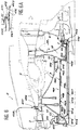
- the turbomachine of FIG. 1, shown partially, is composed of a rotor 1 surrounded by a stator 2 and between which extends an annular stream 3 of gas flow occupied by stages of fixed and movable blades and by a combustion chamber 4.
- a low pressure compressor 5 a high pressure compressor 6, the combustion chamber 4, a high pressure turbine 7 and a low pressure turbine turbine 8 through the annular stream.
- compressors 5 and 6 as well as the turbines 7 and 8 belong to the rotor 1, which therefore comprises in particular a wall 9 of revolution which connects the high pressure compressor 6 to the low pressure turbine 7 and which is surrounded by an internal wall 10 of the combustion chamber 4.
- conduits 11 are established between the walls 9 and 10 and extend from the bottom of various portions of the combustion chamber 4 to a e annular portion of the wall 9 which touches the disc of the high pressure turbine 7 and more precisely to a central part - close to the axis of the turbomachine - of this disc.
- This central part is designated by 12 in the figure 1 and evokes a bulb because it is much thicker than the rest of the disc, which explains why such turbine discs are sometimes called leek.
- the conduits 11 are rigidly fixed to the wall 10 and joined to the wall 9 by a seal 13 which is detailed in FIGS. 2A and 2B. It can be seen that the conduits 11 are provided at this point with an annular and common mouth 14 provided with two seals which can be parallel and circular brush seals 15 and 16 which rub against the wall 9 or, more precisely in the present case, on an extension 17 of this wall 9 formed in one piece with the disc of the turbine 7. All the conduits 11 converge in the mouth 14 which therefore constitutes a collecting chamber for the gas withdrawn.
- Wipers 18 are established on the extension 17 of the wall 9. These are circular and parallel ridges tapered at their free end. They delimit grooves 19 whose bottoms are alternately full and provided with an orifice 20 which passes through the extension 17 and opens into a chamber 21 one face of which is delimited by the bulb 12.
- the mouth 14 is covered with a plate 22 located in front of the edges of the wipers 18 and which is covered with said abradable material on the side facing the wipers 18, or composed only of this material, the essential property of which is to be easily eroded by the friction of the wipers 18 so as not to leave only a minimum clearance depending on the actual adjustment conditions of the parts and thermal expansion.
- the plate 22 is perforated with orifices 23 whose spacing pitch in longitudinal direction is similar to that of the orifices 20, so that they come substantially in extension of them in the situation in FIG. 2A but are offset and halfway between them in the situation in FIG. 2B, which translates relative to FIG. 2A, a relative axial displacement of the conduits 11 and of the mouth 13 with respect to the extension 17 of the wall 9, to the turbine 7 and to the rotor 1.
- the consequence is that, if the gases originating from the chamber combustion 4 flow freely in the chamber 21 after having passed the conduits 11, the orifices 23, the grooves 19 and the orifices 20 in the situation of FIG. 2A, the communication is almost interrupted in the situation of FIG.
- FIG. 2A The situation in FIG. 2A is obtained when the turbomachine rises, when the heating of the structures is much more sensitive in certain areas. rtions of the stator 2 and in particular near the combustion chamber 4 where the combustion is reinforced: the conduits 11 undergo a longitudinal displacement downstream relative to the rotor 1 and the hot gases of the combustion chamber 4 spread freely in the chamber 21 for heating the bulb 12 by blowing on it and thus reducing the thermal gradient in the disc of the high pressure turbine 7.
- the thermal differential When the speed is stabilized, the thermal differential is reduced, the rotor 1 catches up with its delay in heating and expands in turn downstream: the seals 15 and 16 slide on the wall 9 or its extension 17, the wipers 18 pass in front of the plate 22 and the orifices 23, and the heating of the bulb 12 stops when it could have introduced a new thermal gradient after correcting the previous one.
- a pair of plates 24 and 25 is pinched at one end between radial and parallel ribs 26 and 27 of the wall 9 and of the extension 17.
- the plates 24 and 25 then have different shapes moving apart and delimit a clearance 28 nearby of the bulb 12. More specifically, the plate 24 touches the bulb 12 on its upstream lateral face 29 and on its bore face 30, and the plate 25 extends a short distance away, is surrounded by the plate 24 and is connected by its end opposite to that which is pinched to a flange 31 at the downstream end of the bore of the bulb 12.
- the plates 24 and 25 have raised surfaces, crenellated and formed by overlapping projections, so that the game 28 forms zigzags.
- the gas has passed through the outlets 33 of the clearance 28, it spreads in a chamber 34 located between the discs of the high and low pressure turbines 7 and 8 and further delimited on the outside by a ring 35 of integral confinement of the stator 2 and inside by a ferrule 36 belonging to the rotor 1.
- the ferrule 36 is connected, substantially like the plate 25, to a flange 39 of the disc of the low pressure turbine 8 adjacent to the outlet orifices 38.
- This embodiment provides a good heat exchange between the gas and the bulb 12. If one is less demanding, it is possible to remove the plate 24 and replace the plate 25 with a smooth plate to obtain a faster circulation of the gas.
- the bulb 112 has a bilobed shape
- the plate 124 provided as above with projections and slots, is fixed only to the bore face 130 of the bulb 112 and does not extend beyond it, and the plate 125 is smooth , and only pinch between the ribs 26 and 27.
- the chamber 121 opens directly in the clearance 128, which has a significant widening 150 between the lobes of the bulb 112 because the plate 125 is straight up to the collar 31.
- This embodiment constitutes a compromise between that of FIG. 1, where the heat exchange is very good, and that which was mentioned in the previous paragraph and which is particularly simple thanks to the single plate and smooth. The advantages and disadvantages of these two previous embodiments are therefore mixed here.
- the plate 225 is moreover almost similar to that of the second embodiment, but the plate 224 extends between the ribs 26 and 27 and the flange 31 and only touches the bulb 12 over a short extent 252, close to the chamber 21, beyond which it is separated and extends in the middle of the set 228, which it divides in two.
- the orifices 420 open into a chamber 460 whose shape is deeply original since it is an elongated chamber and has nnulaire delimited by two concentric covers 461 and 462.
- the internal cover 461 extends between the wall 459 and a groove 463 located downstream of the bulb 12 of the high pressure turbine 7, a little downstream of the flange 31.
- the external cover 462 is composed of an upstream part 464 and a downstream part 465 which extends the previous one.
- the parts 464 and 465 can slide one over the other by overlapping portions 466 if it is desired to release the bulb 12 to mount or dismount the disc.
- An advantage inherent in this category of embodiments is that the thermal gradient that the disks of the high pressure compressor 6 can undergo is also lessened if the gas withdrawn and already heated is partly blown towards the bore faces of the disks of the compressor 6 in passing through holes 467 and 468 established in two circles in line with said bore faces on the upstream part 464 of the external cowling 462.
- the downstream part 465 of the outer cover 462 extends in front of the bulb 12 and more precisely in front of its upstream face 29 and its bore face 30 by a foraminous portion 469 which evokes FIG. 4. It is in fact pierced with orifices 253 which allow the air taken off to be blown perpendicular to the faces 29 and 30 of the bulb 12.
- the downstream end of the downstream part 465 is provided with elastic lips (FIG. 6A): an external lip 471 pressed against the flange 31 and an internal lip 472 pressed against the internal cowling 461. This guarantees the absence of gas leakage on this side as well as good support of the external cowling 462.
- the conduits 411 or some of them can also lead into an interval 472 between the internal casing 461 and a rotor tube 473 surrounded by this, passing through additional orifices 474 formed in the wall 459. Holes are then provided on the internal cowling 461 near the zone 463. They bear the reference 476 and allow the gas thus sampled to flow towards other parts of the turbomachine.
- the cowlings bear the references 561 and 562 and differ from the previous ones first of all in that the internal cowl 561 is pressed against the flange 31 by a lip 571, and that the external cowl 562, still formed of an upstream part 564 and a downstream part 565, has a conical section 580 and stops in front of the crenellated bore face 330 of the bulb 312 of FIG. 5.
- the chamber 560 is therefore thinned downstream.
- FIG. 8 resembles FIG. 1 in that the downstream part 665 of the external cowling 662 is provided with an end portion 625 which evokes the plate 25 of this embodiment; the plate 24 is maintained as it is, and the gas leaves the chamber 660 intermediate between the cowlings 661 and 662 by passing through holes 683 established through the downstream part 665 in front of the junction of the faces 29 and 30. It rises along the disc either on the upstream side by the front face 29, or on the downstream side by the bore face 30 and the outlet orifices 33.
- the cowls 661 and 662 are both supported on the flange 31.
- FIG. 9 closely resembles that of FIG. 3, since there is in particular the bulb 112 bilobed and a curved plate 124 which matches the hollow bore face 130; the downstream part 765 of the cover 762 is profiled substantially like the plate 125 at the location 725 located in front of the bilobed bulb 112, and the external cover 762 is supported by lips 471 and 472 opposite the flange 31 and the internal cover 461. Holes 683 allow the gas to leave the chamber 760 to blow on the bilobed bulb 112 in front of the entrance to the bore face 130.
- a protuberance 770 is provided in front of the place 725 to limit leaks towards the upstream face of the disc of the high pressure turbine 7, by throttling the passage that the gas must take.
- FIGS. 6 to 9 can also be modified by adopting certain known arrangements such as the addition of a flow control valve to the transit duct 458 of FIG. 6 and by replacing the seal 13 with a conventional seal. brush.
Landscapes
- Engineering & Computer Science (AREA)
- Mechanical Engineering (AREA)
- General Engineering & Computer Science (AREA)
- Turbine Rotor Nozzle Sealing (AREA)
Applications Claiming Priority (2)
| Application Number | Priority Date | Filing Date | Title |
|---|---|---|---|
| FR9313044 | 1993-11-03 | ||
| FR9313044A FR2712029B1 (fr) | 1993-11-03 | 1993-11-03 | Turbomachine pourvue d'un moyen de réchauffage des disques de turbines aux montées en régime. |
Publications (2)
| Publication Number | Publication Date |
|---|---|
| EP0651137A1 true EP0651137A1 (de) | 1995-05-03 |
| EP0651137B1 EP0651137B1 (de) | 1997-12-29 |
Family
ID=9452443
Family Applications (1)
| Application Number | Title | Priority Date | Filing Date |
|---|---|---|---|
| EP94402461A Expired - Lifetime EP0651137B1 (de) | 1993-11-03 | 1994-11-02 | Turbomaschine mit System zur Heizung der Rotorscheiben in der Beschleunigungsphase |
Country Status (4)
| Country | Link |
|---|---|
| US (1) | US5586860A (de) |
| EP (1) | EP0651137B1 (de) |
| DE (1) | DE69407539T2 (de) |
| FR (1) | FR2712029B1 (de) |
Cited By (8)
| Publication number | Priority date | Publication date | Assignee | Title |
|---|---|---|---|---|
| FR2960260A1 (fr) * | 2010-05-21 | 2011-11-25 | Snecma | Turbomachine comprenant un circuit de ventilation de turbine basse pression ameliore |
| CN102787868A (zh) * | 2012-06-27 | 2012-11-21 | 北京航空航天大学 | 一种基于主动温度梯度控制航空发动机涡轮盘应力的方法 |
| CN103046964A (zh) * | 2012-06-27 | 2013-04-17 | 北京航空航天大学 | 一种基于主动温度梯度控制应力的航空发动机涡轮盘 |
| FR2995020A1 (fr) * | 2012-08-29 | 2014-03-07 | Snecma | Turbomachine comprenant un circuit de ventilation a fourreau telescopique |
| WO2014186008A2 (en) | 2013-02-19 | 2014-11-20 | United Technologies Corporation | Gas turbine engine with rotor bore heating |
| WO2015075405A1 (fr) * | 2013-11-25 | 2015-05-28 | Snecma | Turbomachine comprenant un fourreau d'arbre et tube de fourreau associe |
| FR3023588A1 (fr) * | 2014-07-08 | 2016-01-15 | Turbomeca | Ensemble pour turbine destine a proteger un disque de turbine contre des gradients thermiques |
| FR3090729A1 (fr) * | 2018-12-21 | 2020-06-26 | Safran Aircraft Engines | Structure d’etancheite pour turbomachine |
Families Citing this family (25)
| Publication number | Priority date | Publication date | Assignee | Title |
|---|---|---|---|---|
| US6131911A (en) * | 1992-11-19 | 2000-10-17 | General Electric Co. | Brush seals and combined labyrinth and brush seals for rotary machines |
| US5794942A (en) * | 1993-01-08 | 1998-08-18 | The Texas A&M University System | Modulated pressure damper seals |
| FR2748063B1 (fr) * | 1996-04-24 | 1998-05-29 | Snecma | Turbomachine a double flux |
| GB9610018D0 (en) * | 1996-05-14 | 1996-07-17 | Rolls Royce Plc | Gas turbine engine turbine |
| US5984630A (en) * | 1997-12-24 | 1999-11-16 | General Electric Company | Reduced windage high pressure turbine forward outer seal |
| US6035627A (en) * | 1998-04-21 | 2000-03-14 | Pratt & Whitney Canada Inc. | Turbine engine with cooled P3 air to impeller rear cavity |
| US6227801B1 (en) * | 1999-04-27 | 2001-05-08 | Pratt & Whitney Canada Corp. | Turbine engine having improved high pressure turbine cooling |
| US6585482B1 (en) * | 2000-06-20 | 2003-07-01 | General Electric Co. | Methods and apparatus for delivering cooling air within gas turbines |
| IT1319552B1 (it) * | 2000-12-15 | 2003-10-20 | Nuovo Pignone Spa | Sistema per adduzione di aria di raffreddamento in una turbina a gas |
| US6543975B2 (en) | 2001-04-19 | 2003-04-08 | Loading Zone, Llc | Height adjustment system for truck bed divider |
| FR2839745B1 (fr) * | 2002-05-16 | 2005-05-20 | Snecma Moteurs | Turboreacteur avec un carenage stator dans la cavite sous chambre |
| FR2851010B1 (fr) | 2003-02-06 | 2005-04-15 | Snecma Moteurs | Dispositif de ventilation d'un rotor de turbine a haute pression d'une turbomachine |
| EP1614857A1 (de) * | 2004-07-05 | 2006-01-11 | Siemens Aktiengesellschaft | Strömungsmaschine mit einem Rotor der zumindest eine gebohrene Rotorscheibe aufweist |
| FR2892148B1 (fr) * | 2005-10-19 | 2011-07-22 | Snecma | Fourreau d'arbre de turboreacteur et turboreacteur comportant ce fourreau |
| FR2892454B1 (fr) * | 2005-10-21 | 2008-01-25 | Snecma Sa | Dispositif de ventilation de disques de turbine dans un moteur a turbine a gaz |
| US7578656B2 (en) * | 2005-12-20 | 2009-08-25 | General Electric Company | High pressure turbine disk hub with reduced axial stress and method |
| GB0614972D0 (en) * | 2006-07-28 | 2006-09-06 | Rolls Royce Plc | A mounting disc |
| US10415468B2 (en) | 2012-01-31 | 2019-09-17 | United Technologies Corporation | Gas turbine engine buffer system |
| FR3002972B1 (fr) * | 2013-03-06 | 2015-04-17 | Snecma | Dispositif de ventilation d'un carter de stator d'une turbomachine comprenant un ajustement en direction axiale |
| FR3002971B1 (fr) * | 2013-03-06 | 2015-04-17 | Snecma | Dispositif de ventilation d'un carter de stator d'une turbomachine, comprenant un ajustement sur des circonferences |
| US9951621B2 (en) * | 2013-06-05 | 2018-04-24 | Siemens Aktiengesellschaft | Rotor disc with fluid removal channels to enhance life of spindle bolt |
| RU2532458C1 (ru) * | 2013-09-09 | 2014-11-10 | Открытое акционерное общество "Авиадвигатель" | Ротор высокотемпературной турбомашины |
| US10371056B2 (en) | 2015-12-10 | 2019-08-06 | United Technologies Corporation | Multi-source turbine cooling air |
| FR3057300B1 (fr) * | 2016-10-07 | 2018-10-05 | Safran Aircraft Engines | Assemblage d'anneau mobile de turbine de turbomachine |
| EP4624726A1 (de) * | 2024-02-09 | 2025-10-01 | RTX Corporation | Gestapelte kompressorrotorscheiben mit thermischer konditionierungsbaugruppe |
Citations (2)
| Publication number | Priority date | Publication date | Assignee | Title |
|---|---|---|---|---|
| GB2135394A (en) * | 1983-02-22 | 1984-08-30 | Gen Electric | Cooling gas turbine engines |
| EP0468782A2 (de) * | 1990-07-27 | 1992-01-29 | General Electric Company | Gasturbinenrotor und seine Wirkungsweise |
Family Cites Families (5)
| Publication number | Priority date | Publication date | Assignee | Title |
|---|---|---|---|---|
| GB2018362B (en) * | 1978-04-06 | 1982-04-21 | Rolls Royce | Gas turbine engine cooling |
| US4332133A (en) * | 1979-11-14 | 1982-06-01 | United Technologies Corporation | Compressor bleed system for cooling and clearance control |
| FR2570764B1 (fr) * | 1984-09-27 | 1986-11-28 | Snecma | Dispositif de controle automatique du jeu d'un joint a labyrinthe de turbomachine |
| US4882902A (en) * | 1986-04-30 | 1989-11-28 | General Electric Company | Turbine cooling air transferring apparatus |
| US5271711A (en) * | 1992-05-11 | 1993-12-21 | General Electric Company | Compressor bore cooling manifold |
-
1993
- 1993-11-03 FR FR9313044A patent/FR2712029B1/fr not_active Expired - Fee Related
-
1994
- 1994-10-31 US US08/332,101 patent/US5586860A/en not_active Expired - Lifetime
- 1994-11-02 EP EP94402461A patent/EP0651137B1/de not_active Expired - Lifetime
- 1994-11-02 DE DE69407539T patent/DE69407539T2/de not_active Expired - Lifetime
Patent Citations (2)
| Publication number | Priority date | Publication date | Assignee | Title |
|---|---|---|---|---|
| GB2135394A (en) * | 1983-02-22 | 1984-08-30 | Gen Electric | Cooling gas turbine engines |
| EP0468782A2 (de) * | 1990-07-27 | 1992-01-29 | General Electric Company | Gasturbinenrotor und seine Wirkungsweise |
Cited By (15)
| Publication number | Priority date | Publication date | Assignee | Title |
|---|---|---|---|---|
| FR2960260A1 (fr) * | 2010-05-21 | 2011-11-25 | Snecma | Turbomachine comprenant un circuit de ventilation de turbine basse pression ameliore |
| CN102787868A (zh) * | 2012-06-27 | 2012-11-21 | 北京航空航天大学 | 一种基于主动温度梯度控制航空发动机涡轮盘应力的方法 |
| CN103046964A (zh) * | 2012-06-27 | 2013-04-17 | 北京航空航天大学 | 一种基于主动温度梯度控制应力的航空发动机涡轮盘 |
| FR2995020A1 (fr) * | 2012-08-29 | 2014-03-07 | Snecma | Turbomachine comprenant un circuit de ventilation a fourreau telescopique |
| EP2959109A4 (de) * | 2013-02-19 | 2016-06-01 | United Technologies Corp | Gasturbinenmotor mit rotorbohrungsbeheizung |
| WO2014186008A2 (en) | 2013-02-19 | 2014-11-20 | United Technologies Corporation | Gas turbine engine with rotor bore heating |
| US10094296B2 (en) | 2013-02-19 | 2018-10-09 | United Technologies Corporation | Gas turbine engine with rotor bore heating |
| FR3013766A1 (fr) * | 2013-11-25 | 2015-05-29 | Snecma | Turbomachine comprenant un fourreau d'arbre et tube de fourreau associe |
| CN105765167A (zh) * | 2013-11-25 | 2016-07-13 | 斯奈克玛 | 包括轴衬套的涡轮机以及相关的衬套管 |
| RU2668507C1 (ru) * | 2013-11-25 | 2018-10-01 | Сафран Эркрафт Энджинз | Турбомашина, содержащая кожух вала, и соответствующая труба кожуха |
| WO2015075405A1 (fr) * | 2013-11-25 | 2015-05-28 | Snecma | Turbomachine comprenant un fourreau d'arbre et tube de fourreau associe |
| US10267154B2 (en) | 2013-11-25 | 2019-04-23 | Safran Aircraft Engines | Turbomachine comprising a shaft sleeve and associated sleeve tube |
| CN105765167B (zh) * | 2013-11-25 | 2021-03-02 | 斯奈克玛 | 包括轴衬套的涡轮机以及相关的衬套管 |
| FR3023588A1 (fr) * | 2014-07-08 | 2016-01-15 | Turbomeca | Ensemble pour turbine destine a proteger un disque de turbine contre des gradients thermiques |
| FR3090729A1 (fr) * | 2018-12-21 | 2020-06-26 | Safran Aircraft Engines | Structure d’etancheite pour turbomachine |
Also Published As
| Publication number | Publication date |
|---|---|
| FR2712029A1 (fr) | 1995-05-12 |
| US5586860A (en) | 1996-12-24 |
| FR2712029B1 (fr) | 1995-12-08 |
| DE69407539T2 (de) | 1998-05-28 |
| EP0651137B1 (de) | 1997-12-29 |
| DE69407539D1 (de) | 1998-02-05 |
Similar Documents
| Publication | Publication Date | Title |
|---|---|---|
| EP0651137B1 (de) | Turbomaschine mit System zur Heizung der Rotorscheiben in der Beschleunigungsphase | |
| EP0177408B1 (de) | Vorrichtung für die automatische Regelung des Spiels einer Labyrinthdichtung einer Turbomaschine | |
| EP0785339B1 (de) | Gekühlte Turbinenleitschaufel | |
| EP1505261B1 (de) | Vorrichtung für die Regelung von Spalten in einer Gasturbine | |
| EP1586743B1 (de) | Turbinen-Mantelring | |
| US4157232A (en) | Turbine shroud support | |
| FR2498252A1 (fr) | Systeme de refroidissement pour une chemise interieure de chambre de combustion | |
| WO2010046553A1 (fr) | Ventilation d'une turbine haute-pression dans une turbomachine | |
| EP0636765B1 (de) | Kühlung von Turbinenrotorscheibe | |
| EP2042806A1 (de) | Brennkammer einer Strömungsmaschine | |
| CA2827591C (fr) | Carter de turbine comportant des moyens de fixation de secteurs d'anneau | |
| FR2582051A1 (fr) | Appareil de regulation de jeu pour machine a aubes a ecoulement de fluide | |
| EP1482127B1 (de) | Dichtungssystem für den Nebenstrom am Einlass der Nachbrennerdüse einer Turbomaschine | |
| EP1452695B1 (de) | Mit verringertem Kühlluftdurchstrom gekühlte Turbinenschaufel | |
| EP1519009A1 (de) | Turbomaschine mit Luftentnahme für die Kabine über ein Kugelgelengrohr | |
| FR2895766A1 (fr) | Perfectionnements a un systeme de commande du jeu en bout d'ailette | |
| FR2931515A1 (fr) | Turbomachine avec diffuseur | |
| FR2688539A1 (fr) | Stator de turbomachine comprenant des dispositifs de reglage de jeu entre le stator et les aubes du rotor. | |
| FR2832178A1 (fr) | Dispositif de refroidissement pour anneaux de turbine a gaz | |
| EP4416379B1 (de) | Turbinenleitschaufel mit einem ringförmigen dichtelement | |
| FR3109406A1 (fr) | Dispositif de refroidissement d’un carter de turbine | |
| EP4146913B1 (de) | Verbesserte cmc-leitschaufel für eine turbomaschinenturbine | |
| WO2026052915A1 (fr) | Module pour une turbomachine d'aeronef | |
| FR3087826A1 (fr) | Turbomachine comprenant des moyens pour homogeneiser axialement la temperature d'une bague interieure de palier a roulement | |
| WO2026052916A1 (fr) | Module pour une turbomachine d'aeronef |
Legal Events
| Date | Code | Title | Description |
|---|---|---|---|
| PUAI | Public reference made under article 153(3) epc to a published international application that has entered the european phase |
Free format text: ORIGINAL CODE: 0009012 |
|
| 17P | Request for examination filed |
Effective date: 19941117 |
|
| AK | Designated contracting states |
Kind code of ref document: A1 Designated state(s): DE FR GB |
|
| 17Q | First examination report despatched |
Effective date: 19960731 |
|
| GRAG | Despatch of communication of intention to grant |
Free format text: ORIGINAL CODE: EPIDOS AGRA |
|
| GRAG | Despatch of communication of intention to grant |
Free format text: ORIGINAL CODE: EPIDOS AGRA |
|
| GRAH | Despatch of communication of intention to grant a patent |
Free format text: ORIGINAL CODE: EPIDOS IGRA |
|
| GRAH | Despatch of communication of intention to grant a patent |
Free format text: ORIGINAL CODE: EPIDOS IGRA |
|
| GRAA | (expected) grant |
Free format text: ORIGINAL CODE: 0009210 |
|
| AK | Designated contracting states |
Kind code of ref document: B1 Designated state(s): DE FR GB |
|
| GBT | Gb: translation of ep patent filed (gb section 77(6)(a)/1977) |
Effective date: 19971229 |
|
| REF | Corresponds to: |
Ref document number: 69407539 Country of ref document: DE Date of ref document: 19980205 |
|
| PLBE | No opposition filed within time limit |
Free format text: ORIGINAL CODE: 0009261 |
|
| STAA | Information on the status of an ep patent application or granted ep patent |
Free format text: STATUS: NO OPPOSITION FILED WITHIN TIME LIMIT |
|
| 26N | No opposition filed | ||
| REG | Reference to a national code |
Ref country code: GB Ref legal event code: IF02 |
|
| REG | Reference to a national code |
Ref country code: FR Ref legal event code: TP Ref country code: FR Ref legal event code: CD |
|
| REG | Reference to a national code |
Ref country code: FR Ref legal event code: CD |
|
| REG | Reference to a national code |
Ref country code: GB Ref legal event code: 732E Free format text: REGISTERED BETWEEN 20120517 AND 20120523 |
|
| PGFP | Annual fee paid to national office [announced via postgrant information from national office to epo] |
Ref country code: DE Payment date: 20121025 Year of fee payment: 19 |
|
| PGFP | Annual fee paid to national office [announced via postgrant information from national office to epo] |
Ref country code: GB Payment date: 20121025 Year of fee payment: 19 |
|
| PGFP | Annual fee paid to national office [announced via postgrant information from national office to epo] |
Ref country code: FR Payment date: 20131120 Year of fee payment: 20 |
|
| GBPC | Gb: european patent ceased through non-payment of renewal fee |
Effective date: 20131102 |
|
| PG25 | Lapsed in a contracting state [announced via postgrant information from national office to epo] |
Ref country code: DE Free format text: LAPSE BECAUSE OF NON-PAYMENT OF DUE FEES Effective date: 20140603 |
|
| REG | Reference to a national code |
Ref country code: DE Ref legal event code: R119 Ref document number: 69407539 Country of ref document: DE Effective date: 20140603 |
|
| PG25 | Lapsed in a contracting state [announced via postgrant information from national office to epo] |
Ref country code: GB Free format text: LAPSE BECAUSE OF NON-PAYMENT OF DUE FEES Effective date: 20131102 |