EP0651175A1 - Ressort pneumatique de longeur réglable - Google Patents
Ressort pneumatique de longeur réglable Download PDFInfo
- Publication number
- EP0651175A1 EP0651175A1 EP94115359A EP94115359A EP0651175A1 EP 0651175 A1 EP0651175 A1 EP 0651175A1 EP 94115359 A EP94115359 A EP 94115359A EP 94115359 A EP94115359 A EP 94115359A EP 0651175 A1 EP0651175 A1 EP 0651175A1
- Authority
- EP
- European Patent Office
- Prior art keywords
- gas spring
- housing
- polygonal
- section
- spring according
- Prior art date
- Legal status (The legal status is an assumption and is not a legal conclusion. Google has not performed a legal analysis and makes no representation as to the accuracy of the status listed.)
- Withdrawn
Links
Images


Classifications
-
- A—HUMAN NECESSITIES
- A47—FURNITURE; DOMESTIC ARTICLES OR APPLIANCES; COFFEE MILLS; SPICE MILLS; SUCTION CLEANERS IN GENERAL
- A47C—CHAIRS; SOFAS; BEDS
- A47C3/00—Chairs characterised by structural features; Chairs or stools with rotatable or vertically-adjustable seats
- A47C3/20—Chairs or stools with vertically-adjustable seats
- A47C3/30—Chairs or stools with vertically-adjustable seats with vertically-acting fluid cylinder
-
- F—MECHANICAL ENGINEERING; LIGHTING; HEATING; WEAPONS; BLASTING
- F16—ENGINEERING ELEMENTS AND UNITS; GENERAL MEASURES FOR PRODUCING AND MAINTAINING EFFECTIVE FUNCTIONING OF MACHINES OR INSTALLATIONS; THERMAL INSULATION IN GENERAL
- F16F—SPRINGS; SHOCK-ABSORBERS; MEANS FOR DAMPING VIBRATION
- F16F9/00—Springs, vibration-dampers, shock-absorbers, or similarly-constructed movement-dampers using a fluid or the equivalent as damping medium
- F16F9/02—Springs, vibration-dampers, shock-absorbers, or similarly-constructed movement-dampers using a fluid or the equivalent as damping medium using gas only or vacuum
- F16F9/0209—Telescopic
- F16F9/0245—Means for adjusting the length of, or for locking, the spring or dampers
- F16F9/0263—Means for adjusting the length of, or for locking, the spring or dampers characterised by actuation means, e.g. manually-operated lever arrangement
Definitions
- the invention relates to a length-adjustable gas spring according to the preamble of claim 1.
- the invention is therefore based on the object of designing a gas spring of the generic type such that the connection of the trigger device and the gas spring is particularly simple with a particularly simple design of the triggering device of the adjusting device and with a particularly simple design of the associated area of the gas spring Way with high reliability is possible.
- the measures according to the invention ensure that the housing of the trigger device is only pressed into the spacer sleeve of the gas spring against the force of the actuating pin and is rotated by a small amount of angle. It then engages automatically. A release takes place in the opposite direction. Unintentional loosening is practically impossible. They are too there are no externally accessible parts that can be damaged or broken off.
- a polygonal area is not only to be understood as a uniform square, hexagonal or octagonal profile, but also in the broadest sense of a non-circular profile, possibly with projections that enable locking after twisting.
- FIG. 1 an office chair 1 is shown.
- This has a chair frame 3 which is supported on the floor by rollers 2 and to which an upwardly projecting chair column 4 is attached.
- This has a guide tube 5, in which a length-adjustable gas spring 6 is arranged in such a way that its piston rod is attached to the bottom of the guide tube 5, while the housing 7 of the gas spring 6 is slidably guided in the guide tube 5.
- the upper end of the housing 7 is attached to a seat support 9 of the chair carrying a seat 8.
- the chair has armrests 10, 10 'and, in the usual way, a backrest 11 which can be pivoted in the usual way.
- the seat support 9 with the seat 8 can be adjusted by corresponding length adjustment of the gas spring 6 in accordance with the vertical height adjustment arrow 12, while the backrest 11 can be adjusted in accordance with the swivel direction arrow 13.
- the type of arrangement of a length-adjustable gas spring 6 in a guide tube 5 as a height-adjustable chair column is generally known from DE-PS 19 31 012 (corresponding to US Pat. No. 3,711,054 or JP-PS 892 209) and is common in practice.
- the length-adjustable gas spring 6 is known from DE-PS 18 12 282 (corresponding to US-PS 3 656 593 and JP-PS 846 405) and is widely used in practice.
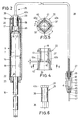
- a length-adjustable gas spring 6 is shown, the housing 7 is arranged in an additional, essentially cylindrical support tube 14.
- the already mentioned piston rod 15 is led out of one end of the housing 7 of the gas spring 6, while an actuating pin 16 for actuating a valve located in the housing 7 protrudes from the end of the housing 7 opposite the piston rod outlet, which valve is used to adjust the length of the gas spring 6 by means of the actuating pin 16 must be operated.
- a hydraulic adjustment device 25 is provided, which consists of a hydraulic release device 26, a hydraulic actuation device 27 and a pressure-resistant, flexible hydraulic hose 28 connecting them.
- the triggering device 26 has an essentially cylindrical housing 29, in the cylindrical hydraulic chamber 30 of which a triggering piston 31 is guided so as to be displaceably sealed by means of a seal 32.
- the hydraulic chamber 30 is closed off at one end by the release piston 31.
- the housing 29 is provided with a connecting piece 33 for the hydraulic hose 28, in which the latter is fixed by means of a hose clamp coupling 34, so that the hose 28 is connected to the hydraulic chamber 30.
- the trigger piston 31 has on its outward-facing surface a receiving recess 35, for example, delimited or formed by an annular collar, for the actuating pin 16 of the gas spring 6.
- the housing 29 of the release device 26 has, at its area remote from the connecting piece 23, that is to say adjacent to the actuating pin 16 of the gas spring 6, an external hexagon section 36 whose wrench size corresponds to the diameter of a cylindrical section 38 of the housing 29.
- the spacer sleeve 20 has an inner hexagon area 37 concentric to the axis 18, which is designed such that the outer hexagonal section 36 of the housing 29 can be inserted into the spacer sleeve 20 easily but essentially without play.
- section 38 of the housing 29 likewise lies — radially to the axis 18 — essentially without play in the internal hexagon region 37 of the spacer sleeve 20.
- the spacer sleeve 20 has, following the hollow inner hexagon region 37 toward the gas spring 6, a cylindrical recess 39 which is enlarged relative to the region 37 and concentric with the axis 18.
- a stop surface 40 is formed at the transition from the area 37 to the recess 39.
- Recesses 40a are formed in this stop surface 40, which delimit a hexagon profile that corresponds to that of the inner hexagon region 37, but are offset relative to the latter by an angle ⁇ of 30 ° about the axis 18, as can be seen in particular in FIG. 4 .
- the angle a is equal to half the angle b of 60 ° of the hexagon area 37.
- the spacer sleeve 20 is provided on its outside with ribs 41 which are supported against the inside of the fastening section 17. At its end facing the housing 7 of the gas spring 6, it is designed with a stop 42 for abutment against the end face 21 of the housing 7. It consists of plastic or a die-cast zinc or aluminum. Basically, it consists of a softer material than the steel housing 7 of the gas spring 6 or as the support tube 14, which is also made of steel.
- the actuating device 27 also has an essentially cylindrical housing 43 in which a cylindrical hydraulic chamber 44 is formed, in which an actuating piston 45 can be displaced in a sealed manner by means of a seal 46.
- An operating pin 47 is formed in one piece with the actuating piston 45 and is led out of one end of the housing 43.
- a connecting piece 48 is provided, in which the hydraulic hose 28 is fixed by means of a hose clamp coupling 49.
- This coupling 49 is designed as a screw coupling and can therefore be released non-destructively.
- An annular groove 50 is formed on the outside of the housing 43, by means of which the actuating device 27 can be fastened, for example, to the armrest 10 of the chair 1.
- the hydraulic hose 28 is guided, for example, through the armrest 10 to the seat support.
- the hydraulic chamber 30, the hydraulic hose 28 and the hydraulic chamber 44 are filled with incompressible liquid.
- the trigger piston 31 When pressure is exerted on the operating pin 47 of the actuating device 27 into its housing 43, the trigger piston 31 is consequently pushed away from the connecting piece 33 of the housing 29 and presses the actuating pin 16 of the gas spring 6 into its housing 7, thereby the valve located in the housing 7 is opened.
- the gas spring 6 can then be adjusted in length by extending its piston rod 15 out of the housing 7 or by pushing the piston rod 15 into the housing 7.
- the gas pressure in the gas spring 6 pushes the actuating pin 16 out of it again and consequently pushes the release piston 31 in the direction of the connecting piece 33 of the housing 29.
- the liquid displaced from the hydraulic chamber 30 flows through the hydraulic Hose 28 into the hydraulic chamber 44 and pushes the actuating piston 45 back into the starting position with the operating pin 47.
- the actuating piston 45 cannot be inadvertently removed from the housing 43 with the operating pin 47, it is provided with an annular collar 51 which comes to bear against an outer stop edge 52 of the housing 43.
- the adjustment device 25 is therefore in the ready-to-use state an independent, storable, dispatchable and installable component.
- the triggering device 26 namely its outer hexagonal section 36, is inserted into the inner hexagonal area 37 of the spacer sleeve 20 until the Actuating pin 16 rests in the recess 35 of the trigger piston 31 against the latter.
- the housing 29 is then pressed further into the spacer sleeve 20 until the external hex section 36 emerges from the internal hex region 37.
- the actuating pin 16 has been at least partially pressed into the housing 7 of the gas spring 6. Now the housing 29 of the release device 26 is rotated by the angle ⁇ of 30 °, so that the outer hexagon section 36 is in register with the recesses 40a in the stop surface 40.
- the actuating pin 16 removes it so far from the spacer sleeve 20 pushed out until the outer hexagon section 36 abuts the base 40b of the recesses 40a.
- the recesses 40a have a depth c parallel to the axis 18, which is only so large that the outer hexagon section 36 is pressed by the actuating pin 16 of the gas spring 6 against the base 40b of the recesses 40a.
- the triggering device 26 is therefore also fixed in the direction of the axis 18 essentially without play in the spacer sleeve 20. Unintentional loosening is impossible.
- the housing 29 can also be provided on its connecting piece 33 with a hexagonal profile 40c, whereby the assembly or disassembly of the release device 26 can be facilitated.
- the triggering device 26 and the actuating device 27 consist of suitable plastic or aluminum.
- the adjustment device 25 can be given a translation or a reduction.
- the diameter D of the trigger piston 31 is approximately twice as large as the diameter d of the actuating piston 45. In the specific case, this has the consequence that the force to be applied by the user on the operating pin 47 for adjustment is only about a quarter of the force that is to be applied to insert the actuating pin 16 into the gas spring 6.
- the housing 7 'of the gas spring 6' can of course also be extended accordingly, that is to say it can be provided with a fastening section 17 'projecting beyond the actuating pin 16, as is known for the gas spring itself from DE-OS 19 58 874 is.
- a valve body 53 of the above-mentioned valve 54 of the gas spring 6 ' is supported against the edge 19 via the spacer sleeve 20.
- the actuating pin 16 is part of the valve 54 and is displaceable in the valve body 53 in the direction of the axis 18.
- the design of the valve itself and the rest of the gas spring is - as already stated above - generally known.
- FIG. 7 also shows a measure of how the housing 29 of the release device 26 can be arranged in the spacer sleeve 20 without play in the direction of the axis 18.
- a small suspension element 55 for example a rubber ring or the like, is arranged between the hexagonal profile 40c, which has the function of a protruding edge, and the spacer sleeve 20, which presses the housing 29 out of the spacer sleeve 20 seeks, so that the outer hexagonal portion 36 is held in the recesses 40a in the spacer sleeve 20.
- FIG. 7 also shows a type of fastening of the hydraulic hose 28 in the housing 29 of the release device 26 which is modified compared to the above exemplary embodiment.
- the hose 28 is in the housing 29 by means of a hollow clamping screw 56 surrounding it and a clamping ring 57 compressed by the latter held.
- This type of fastening of the hose 28 to the housing 29 and in particular also the axially backlash-free mounting of the housing 29 in the spacer sleeve 20 by means of the spring element 55 can of course also be used in the same way in the exemplary embodiment according to FIGS. 2 to 6.
- FIG. 8 shows the upper end of the housing 7 'of the gas spring 6' with its fastening section 17 'including an identical spacer sleeve 20.
- a sliding body 58 is provided, which is arranged essentially in the inner polygonal region 37 of the spacer sleeve 20 so as to be displaceable in the direction of the axis 18. It bears against the actuating pin 16 of the gas spring 6 '.
- the sliding body 58 is provided with holding fingers 59 which extend towards the housing 7 'of the gas spring 6' and which engage with barb-like projections 60 projecting radially outwards under the stop surface 40, as a result of which the sliding body 58 prevents accidental falling out or pulling out of the spacer sleeve 20 is secured against the actuating pin 16 while at the same time largely free of play.
- the projections 60 can slide downward in the hexagon area 37.
- the actuation takes place by means of a pivotable actuation lever which is mounted on the chair 1 in the usual way and which comes to bear against an axially adjustable outer surface 61 of the sliding body 58.
- This outer surface 61 is formed by the head of a screw 62 which is screwed into the sliding body 58. By Corresponding rotation of the screw 62, the position of the outer surface 61 can be changed so that there is play-free contact with the operating lever, not shown.
- This configuration of the spacer sleeve 20 with the sliding body 58 is known and is shown and described in principle in EP 0 133 523 B2 (corresponding to JP-GM 1 818 870). The description of this embodiment serves the purpose of demonstrating that the triggering device 26 can, due to its design, optionally be used instead of a sliding body 58 for a purely manual triggering by means of an operating lever mounted on the chair 1, without the gas spring 6 'with the spacer sleeve 20 must be changed. This applies in the same way to the gas spring 6 with the support tube 14.
- FIG. 9 largely corresponds to that according to FIG. 7, which is why the same reference numbers have been used in this regard and reference can be made to the description of FIG. 7.
- the housing 29 ' is only provided with a very short external hexagon section 36', as a result of which the housing 29 'becomes shorter overall.
- the trigger piston 31 ' is provided at its end facing the actuating pin 16 of the gas spring 6' with a projection 63 in the form of a pin which bears against the actuating pin 16.
- an annular groove 64 is formed, on which a conical spring 65 is held, which is supported against the valve body 53 of the valve 54.
- the cone spring 65 is a prestressed compression spring in the assembled state.
- this spring 65 has the same function as the spring element 55 in the embodiment according to FIG. 7, although the spring 65 has the advantage that it is effective over the entire possible path of the piston 31 'and the actuating pin 16.
- the prestressed spring 65 acts in the extension direction of the actuating pin 16 over the full path of the piston 31 'and the actuating pin 16. It thus supports its extension movement and helps to overcome any frictional forces that may be present in the release device 26 or the actuation device 27, so that the valve 54 is reliably closed when the actuation device 27 is released.
Landscapes
- Engineering & Computer Science (AREA)
- General Engineering & Computer Science (AREA)
- Mechanical Engineering (AREA)
- Chairs Characterized By Structure (AREA)
- Vehicle Body Suspensions (AREA)
- Registering, Tensioning, Guiding Webs, And Rollers Therefor (AREA)
- Fluid-Damping Devices (AREA)
Applications Claiming Priority (5)
| Application Number | Priority Date | Filing Date | Title |
|---|---|---|---|
| DE9315245U DE9315245U1 (de) | 1993-10-09 | 1993-10-09 | Längenverstellbare Gasfeder |
| DE4336616 | 1993-10-27 | ||
| DE4336616 | 1993-10-27 | ||
| DE4417027 | 1994-05-14 | ||
| DE4417027A DE4417027A1 (de) | 1993-10-09 | 1994-05-14 | Längenverstellbare Gasfeder |
Publications (1)
| Publication Number | Publication Date |
|---|---|
| EP0651175A1 true EP0651175A1 (fr) | 1995-05-03 |
Family
ID=45532085
Family Applications (1)
| Application Number | Title | Priority Date | Filing Date |
|---|---|---|---|
| EP94115359A Withdrawn EP0651175A1 (fr) | 1993-10-09 | 1994-09-29 | Ressort pneumatique de longeur réglable |
Country Status (2)
| Country | Link |
|---|---|
| EP (1) | EP0651175A1 (fr) |
| DE (2) | DE9315245U1 (fr) |
Cited By (5)
| Publication number | Priority date | Publication date | Assignee | Title |
|---|---|---|---|---|
| EP0891727A3 (fr) * | 1997-07-17 | 1999-11-10 | Nerio Righi | Ressort pneumatique, notamment pour chaises de bureau |
| EP1533540A1 (fr) * | 2003-11-18 | 2005-05-25 | SUSPA Holding GmbH | Ressort de compression réglable en longueur |
| EP1935284A3 (fr) * | 2006-12-21 | 2008-08-20 | Fumoto Giken Co., Ltd. | Dispositif de fonctionnement |
| EP2060203A3 (fr) * | 2006-12-21 | 2011-06-01 | Fumoto Giken Co., Ltd. | Dispositif de fonctionnement |
| US20120186496A1 (en) * | 2006-12-21 | 2012-07-26 | Fumoto Giken Co., Ltd. | Operating device |
Families Citing this family (5)
| Publication number | Priority date | Publication date | Assignee | Title |
|---|---|---|---|---|
| DE10062773C1 (de) * | 2000-12-15 | 2002-07-25 | Stabilus Gmbh | Kolben-Zylinderaggregat mit einer Verstelleinrichtung |
| DE10140580A1 (de) | 2000-12-16 | 2002-06-20 | Stabilus Gmbh | Kolben-Zylinderaggregat mit einer geschwindigkeitsabhängigen Dämpfkraft |
| DE10302870B3 (de) * | 2003-01-28 | 2004-08-05 | Stabilus Gmbh | Verstellvorrichtung |
| RU2237205C1 (ru) * | 2003-04-21 | 2004-09-27 | ООО "Инженерный центр обеспечения безопасности в промышленности" | Амортизатор |
| RU2235929C1 (ru) * | 2003-04-21 | 2004-09-10 | ООО "Инженерный центр обеспечения безопасности в промышленности" | Амортизатор |
Citations (2)
| Publication number | Priority date | Publication date | Assignee | Title |
|---|---|---|---|---|
| EP0366128A1 (fr) * | 1988-10-26 | 1990-05-02 | Stabilus GmbH | Dispositif de longueur réglable et verrouillable |
| DE4032398A1 (de) * | 1989-10-19 | 1991-04-25 | Stabilus Gmbh | Konstruktionseinheit, insbesondere sitz- oder liegemoebel |
-
1993
- 1993-10-09 DE DE9315245U patent/DE9315245U1/de not_active Expired - Lifetime
-
1994
- 1994-05-14 DE DE4417027A patent/DE4417027A1/de not_active Withdrawn
- 1994-09-29 EP EP94115359A patent/EP0651175A1/fr not_active Withdrawn
Patent Citations (2)
| Publication number | Priority date | Publication date | Assignee | Title |
|---|---|---|---|---|
| EP0366128A1 (fr) * | 1988-10-26 | 1990-05-02 | Stabilus GmbH | Dispositif de longueur réglable et verrouillable |
| DE4032398A1 (de) * | 1989-10-19 | 1991-04-25 | Stabilus Gmbh | Konstruktionseinheit, insbesondere sitz- oder liegemoebel |
Cited By (5)
| Publication number | Priority date | Publication date | Assignee | Title |
|---|---|---|---|---|
| EP0891727A3 (fr) * | 1997-07-17 | 1999-11-10 | Nerio Righi | Ressort pneumatique, notamment pour chaises de bureau |
| EP1533540A1 (fr) * | 2003-11-18 | 2005-05-25 | SUSPA Holding GmbH | Ressort de compression réglable en longueur |
| EP1935284A3 (fr) * | 2006-12-21 | 2008-08-20 | Fumoto Giken Co., Ltd. | Dispositif de fonctionnement |
| EP2060203A3 (fr) * | 2006-12-21 | 2011-06-01 | Fumoto Giken Co., Ltd. | Dispositif de fonctionnement |
| US20120186496A1 (en) * | 2006-12-21 | 2012-07-26 | Fumoto Giken Co., Ltd. | Operating device |
Also Published As
| Publication number | Publication date |
|---|---|
| DE4417027A1 (de) | 1995-07-13 |
| DE9315245U1 (de) | 1994-01-05 |
Similar Documents
| Publication | Publication Date | Title |
|---|---|---|
| DE3429424C2 (fr) | ||
| DE3420528C2 (fr) | ||
| DE2942455C2 (fr) | ||
| EP0622037B1 (fr) | Colonne règlable pour sièges, tables ou similaires | |
| EP0789157A2 (fr) | Ressort à gaz ajustable en longueur | |
| DE2338304A1 (de) | Drehmomentschluessel | |
| DE8422413U1 (de) | Längenverstellbare Gasfeder für eine blockierbare Hubvorrichtung zum strufenlosen Verstellen von Stuhlsitzen, Tischplatten oder ähnlichen Möbelstücken | |
| EP0707160B1 (fr) | Ressort pneumatique de longueur réglable | |
| EP0545444A1 (fr) | Dispositif de remplissage pour vannes de bouteilles à gaz, en particulier des bouteilles d'acétylène | |
| DE2428776C2 (de) | Vorrichtung zur lösbaren Halterung einer längenverstellbaren Säule an einer Stuhlsitzplatte, Tischplatte o.dgl. | |
| EP0133524B1 (fr) | Dispositif de levage verrouillable, permettant le réglage de manière continue de sièges, dessus de table ou d'éléments de mobilier similaires, et ressort à gaz de longueur réglable pour un tel dispositif de levage | |
| DE3437097C2 (de) | Stufenlos verstellbare Hubvorrichtung | |
| DE2741998A1 (de) | Schwingungsdaempfer fuer fahrzeuge | |
| DE3803407A1 (de) | Hoehenverstellvorrichtung | |
| DE4417027A1 (de) | Längenverstellbare Gasfeder | |
| EP1559349B1 (fr) | Colonne support télescopique | |
| DE19515368A1 (de) | Längenverstellbare Gasfeder | |
| EP0410196B1 (fr) | Dispositif de longueur ajustable | |
| DE1267925B (de) | Membrangesteuerter Druckminderer mit einem auf der Membran angeordneten UEberdruckventil | |
| DE29500415U1 (de) | Bausatz für Kleinmöbel | |
| EP0564776A1 (fr) | Ressort à gaz réglable en longueur et chaise avec tel ressort | |
| DE4445190A1 (de) | Längenverstellbare Gasfeder für Stühle, Tische od. dgl. | |
| DE29724446U1 (de) | Längenverstellbare Säule für Stühle o.dgl. | |
| DE2757901C3 (de) | Anschlußvorrichtung für einen Metallschlauch | |
| DE7434102U (de) | Höhenverstellbare Säule |
Legal Events
| Date | Code | Title | Description |
|---|---|---|---|
| PUAI | Public reference made under article 153(3) epc to a published international application that has entered the european phase |
Free format text: ORIGINAL CODE: 0009012 |
|
| AK | Designated contracting states |
Kind code of ref document: A1 Designated state(s): DE ES IT |
|
| STAA | Information on the status of an ep patent application or granted ep patent |
Free format text: STATUS: THE APPLICATION IS DEEMED TO BE WITHDRAWN |
|
| 18D | Application deemed to be withdrawn |
Effective date: 19950608 |