EP0651221B1 - Konstruktion einer Endkammer für einen Wärmetauscher - Google Patents
Konstruktion einer Endkammer für einen Wärmetauscher Download PDFInfo
- Publication number
- EP0651221B1 EP0651221B1 EP94303888A EP94303888A EP0651221B1 EP 0651221 B1 EP0651221 B1 EP 0651221B1 EP 94303888 A EP94303888 A EP 94303888A EP 94303888 A EP94303888 A EP 94303888A EP 0651221 B1 EP0651221 B1 EP 0651221B1
- Authority
- EP
- European Patent Office
- Prior art keywords
- piece
- header
- tank
- heat exchanger
- tubes
- Prior art date
- Legal status (The legal status is an assumption and is not a legal conclusion. Google has not performed a legal analysis and makes no representation as to the accuracy of the status listed.)
- Expired - Lifetime
Links
- 238000010276 construction Methods 0.000 title abstract description 10
- 230000002093 peripheral effect Effects 0.000 claims abstract description 18
- 230000000712 assembly Effects 0.000 claims abstract description 13
- 238000000429 assembly Methods 0.000 claims abstract description 13
- 150000001875 compounds Chemical class 0.000 claims description 3
- 230000008901 benefit Effects 0.000 description 5
- 239000012530 fluid Substances 0.000 description 3
- 238000004378 air conditioning Methods 0.000 description 2
- 238000005219 brazing Methods 0.000 description 2
- 238000001816 cooling Methods 0.000 description 2
- 239000000446 fuel Substances 0.000 description 2
- 238000000034 method Methods 0.000 description 2
- 238000005057 refrigeration Methods 0.000 description 2
- WYTGDNHDOZPMIW-RCBQFDQVSA-N alstonine Natural products C1=CC2=C3C=CC=CC3=NC2=C2N1C[C@H]1[C@H](C)OC=C(C(=O)OC)[C@H]1C2 WYTGDNHDOZPMIW-RCBQFDQVSA-N 0.000 description 1
- 238000005253 cladding Methods 0.000 description 1
- 238000004891 communication Methods 0.000 description 1
- 238000009434 installation Methods 0.000 description 1
- 239000007788 liquid Substances 0.000 description 1
- 239000000463 material Substances 0.000 description 1
- 239000002184 metal Substances 0.000 description 1
- 230000000717 retained effect Effects 0.000 description 1
- 238000007789 sealing Methods 0.000 description 1
Images
Classifications
-
- F—MECHANICAL ENGINEERING; LIGHTING; HEATING; WEAPONS; BLASTING
- F28—HEAT EXCHANGE IN GENERAL
- F28F—DETAILS OF HEAT-EXCHANGE AND HEAT-TRANSFER APPARATUS, OF GENERAL APPLICATION
- F28F9/00—Casings; Header boxes; Auxiliary supports for elements; Auxiliary members within casings
- F28F9/02—Header boxes; End plates
- F28F9/0219—Arrangements for sealing end plates into casing or header box; Header box sub-elements
- F28F9/0224—Header boxes formed by sealing end plates into covers
-
- F—MECHANICAL ENGINEERING; LIGHTING; HEATING; WEAPONS; BLASTING
- F28—HEAT EXCHANGE IN GENERAL
- F28D—HEAT-EXCHANGE APPARATUS, NOT PROVIDED FOR IN ANOTHER SUBCLASS, IN WHICH THE HEAT-EXCHANGE MEDIA DO NOT COME INTO DIRECT CONTACT
- F28D1/00—Heat-exchange apparatus having stationary conduit assemblies for one heat-exchange medium only, the media being in contact with different sides of the conduit wall, in which the other heat-exchange medium is a large body of fluid, e.g. domestic or motor car radiators
- F28D1/02—Heat-exchange apparatus having stationary conduit assemblies for one heat-exchange medium only, the media being in contact with different sides of the conduit wall, in which the other heat-exchange medium is a large body of fluid, e.g. domestic or motor car radiators with heat-exchange conduits immersed in the body of fluid
- F28D1/04—Heat-exchange apparatus having stationary conduit assemblies for one heat-exchange medium only, the media being in contact with different sides of the conduit wall, in which the other heat-exchange medium is a large body of fluid, e.g. domestic or motor car radiators with heat-exchange conduits immersed in the body of fluid with tubular conduits
- F28D1/053—Heat-exchange apparatus having stationary conduit assemblies for one heat-exchange medium only, the media being in contact with different sides of the conduit wall, in which the other heat-exchange medium is a large body of fluid, e.g. domestic or motor car radiators with heat-exchange conduits immersed in the body of fluid with tubular conduits the conduits being straight
- F28D1/0535—Heat-exchange apparatus having stationary conduit assemblies for one heat-exchange medium only, the media being in contact with different sides of the conduit wall, in which the other heat-exchange medium is a large body of fluid, e.g. domestic or motor car radiators with heat-exchange conduits immersed in the body of fluid with tubular conduits the conduits being straight the conduits having a non-circular cross-section
- F28D1/05366—Assemblies of conduits connected to common headers, e.g. core type radiators
- F28D1/05383—Assemblies of conduits connected to common headers, e.g. core type radiators with multiple rows of conduits or with multi-channel conduits
-
- F—MECHANICAL ENGINEERING; LIGHTING; HEATING; WEAPONS; BLASTING
- F28—HEAT EXCHANGE IN GENERAL
- F28F—DETAILS OF HEAT-EXCHANGE AND HEAT-TRANSFER APPARATUS, OF GENERAL APPLICATION
- F28F9/00—Casings; Header boxes; Auxiliary supports for elements; Auxiliary members within casings
- F28F9/02—Header boxes; End plates
-
- F—MECHANICAL ENGINEERING; LIGHTING; HEATING; WEAPONS; BLASTING
- F28—HEAT EXCHANGE IN GENERAL
- F28D—HEAT-EXCHANGE APPARATUS, NOT PROVIDED FOR IN ANOTHER SUBCLASS, IN WHICH THE HEAT-EXCHANGE MEDIA DO NOT COME INTO DIRECT CONTACT
- F28D21/00—Heat-exchange apparatus not covered by any of the groups F28D1/00 - F28D20/00
- F28D2021/0019—Other heat exchangers for particular applications; Heat exchange systems not otherwise provided for
- F28D2021/008—Other heat exchangers for particular applications; Heat exchange systems not otherwise provided for for vehicles
- F28D2021/0084—Condensers
Definitions
- This invention relates to a heat exchanger comprising the features of the preamble of claim 1.
- Such heat exchangers having a combined header and tank construction are usable in moderately high pressure applications as, for example, cooling systems including high pressure radiators, and air conditioners condensers and/or evaporators in vehicles.
- heat exchangers of this type are relatively small as compared to conventional heat exchangers.
- the use of the combined header and tank constructions shown in US-A-4 998 580 result in a heat exchanger having a lesser dimension measured transverse to the direction of elongation of the header/tank assembly than would be the case if conventional headers were used. This allows such a heat exchanger to be more readily situated in modern vehicles wherein aerodynamics are critical to achieving better fuel economy.
- header and tank constructions are in the form of cylindrical tubes.
- the header/tank assembly to header/tank assembly dimension of the heat exchanger could be further reduced if the header and tank constructions were somewhat flattened as, for example, to tube constructions of generally oval cross section.
- One component may be termed a header piece, which forms half of the oval and which is slotted to receive the ends of flattened tubes.
- the other piece is a tank piece which is also partially oval shaped and which is fitted about the header piece and brazed thereto to define a two piece tube which serves as combined header and tank. Because the minor axis of an oval is less than the major axis, it will be appreciated that one dimension of the header and tank construction may be reduced through this method such that the header/tank assembly to header/tank assembly dimension of a heat exchanger can be reduced over that of an otherwise identical heat exchanger employing cylindrical tubes as header and tank constructions.
- the present invention is directed to overcoming one or more of the above problems.
- the crests of the peripheral flange of the tank piece abut the header piece.
- the crests and valleys define a castellated edge on the peripheral flange of the tank piece.
- the valleys clear the tube ends by at least a few fortieths of a millimetre (a few thousandths of an inch).
- convex domes in the form of continuous compound curves are located between each of the slots along the length of the header piece.
- the slots extend substantially completely between opposite parts of the peripheral flange of the header piece.
- headers/tank assemblies are of generally oval cross section.
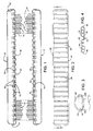
- FIG. 1 An exemplary embodiment of a heat exchanger made according to the invention is illustrated in the drawings.
- the same will be intended for moderately high pressure operation as, for example, as a condenser or an evaporator in a refrigeration or air conditioning system, or even as a radiator in a relatively high pressure engine cooling system.
- the heat exchanger will find use in a vehicular application, but the invention is not so limited.
- the heat exchanger could be used for the purposes mentioned previously where the systems are stationary.
- the heat exchanger includes a first header/tank assembly, generally designated 10, which is elongated and a second, elongated header/tank assembly, generally designated 12.
- the header/tank assembly 10 is parallel to the header/tank assembly 10 and spaced therefrom.
- a plurality of tubes 14 of flattened cross section extend between the headers/tank assemblies 10 and 12 and are in fluid communication with the interiors thereof.
- Serpentine fins 16 are located between and bonded to adjacent ones of the tubes 14. Needless to say, various fittings (not shown) to provide ports, baffles, etc. for the headers 10, 12 are included in the assembly. In the usual case, the entire heat exchanger will have its various components assembled to each other as by brazing.
- the headers/tank assemblies 10 and 12 are identical, one to the other. Consequently, only the header/tank assembly 10 will be described.
- the header/tank assembly 10 is made up of two components. One is a header piece 20 and the second is a tank piece 22.
- the header piece 20 includes a peripheral flange 24 surrounding a partial oval surface 26. Within the overall surface 26 there are provided a plurality of tube slots 28 which receive the ends of the tubes 14.
- a cross section of a typical tube is illustrated in Fig. 4 and the same is seen to include flat walls 30 to which the fins 14 are bonded, and interior webs 32 defining a plurality of interior passages 34, preferably of a hydraulic diameter of 1.8 mm (0.070 inches) or less if the heat exchanger is to be used in a refrigeration or air conditioning application.
- the distance between the flat sides 30 is referred to as the tube minor dimension and the dimension of the tube transverse thereto, that is, extending between ends 36, is referred to as a tube major dimension.
- the same are transverse to the direction of elongation of the header/tank assembly 10 and are configured to have a shape and size virtually identical to the cross section of the tubes 14.
- the ends of the tubes 14 may be snugly received in the slots 28.
- both the header piece 20 and the tank piece 22 are provided with braze cladding. Because the slots 28 are formed as illustrated in Figs. 1 and 2, that is, by being directed into the oval surface 26, it will be appreciated that braze clad will be adjacent each of the slots 28 to unite with tubes 14 in a brazing operation.
- each dome 40 has a curved cross section extending continuously between adjacent ones of the slots 28 in the direction of elongation of the header/tank assembly 10.
- the surface 26 is also in the form of a curve that extends continuously between opposite sides of the peripheral flange 24.
- each of the domes 40 is in the form of a continuous compound curve. The use of such domes enhance the pressure resistance of the ultimate heat exchanger by minimizing the flexure of the header piece 20 in response to pressure in the vicinity of the tube to header joints established between the headers/tank assemblies 10 and 12 and the ends of the tubes 14.
- the tank piece 22 also includes a peripheral flange 42.
- the peripheral flange 42 is nested snugly within the flange 24 and bonded thereto.
- braze clad is located on the surface 26 of the header piece 20 as well as the exterior surface 44 of the tank piece 22. It will also be appreciated from Fig. 3 that the tank piece 22 is of concave configuration.
- the edge of the flange 42 of the tank piece 22 is castellated. That is to say, the same includes a plurality of valleys 50 separated by crests 52 such that the resulting configuration looks somewhat like a square wave.
- the valleys 50 are of a width in the direction of elongation of the header/tank assembly 10 that is greater than the minor dimension of the tubes 14 at their ends.
- the width of the valleys 50 is three times greater than the tube minor dimension although it is not necessary that such a relationship be maintained. It is only necessary that the valleys 50 be somewhat wider than the tube minor dimensions.
- the crests 52 are in abutment with the interior surface 54 of the header piece 40 along the entire length thereof. This abutment establishes the interior volume between the pieces 20 and 22.
- the slots 28 may extend the entire distance between opposite parts of the flange 24 of the header piece 20 that is plainly evident in Fig. 2.
- This allows one to use tubes 14 having the largest possible tube major dimension without increasing the cross sectional profile transverse to the direction of elongation of each header/tank assembly, and still avoid problems with pressure drops on the interior.
- valleys 50 serve as reliefs about the ends of the tubes 14 as they are received within the slots 28 and brazed thereto.
- the depths of the valleys 50 only need such that a few thousandths of an inch clearance exists between the ends of the tubes 14 to the edge of the flange 42, depending upon the brazed materials being used.
- a major point of the use of the valleys 50 is to prevent, during the braze process, liquid braze metal at the interface between the flanges 24 and 42 from flowing onto the open ends of the tubes 14 and sealing one or more of the passages 34 therein.
- the tube major dimension may be maximized for any header/tank assembly of a given width to achieve the benefits afforded by the use of tubes having large major dimensions.
- the advantages of a two piece, oval cross section header/tank assembly in terms of providing a reduced profile header/tank assembly are retained.
Landscapes
- Engineering & Computer Science (AREA)
- Physics & Mathematics (AREA)
- Thermal Sciences (AREA)
- Mechanical Engineering (AREA)
- General Engineering & Computer Science (AREA)
- Heat-Exchange Devices With Radiators And Conduit Assemblies (AREA)
- Filling Or Discharging Of Gas Storage Vessels (AREA)
- Details Of Heat-Exchange And Heat-Transfer (AREA)
- Power Steering Mechanism (AREA)
- Compression-Type Refrigeration Machines With Reversible Cycles (AREA)
- Separation By Low-Temperature Treatments (AREA)
Claims (8)
- Wärmetauscher, mit einer Vielzahl abgeflachter Rohre (14), von denen jedes eine kleinere und quer dazu eine größere Abmessung besitzt und die in Abständen zueinander parallel angeordnet sind; zwischen den Rohren und in wärmetauschender Beziehung mit diesen angebrachten Rippen (16); und einem Paar im Abststand zueinander angeordneter paralleler langgestreckter Verteiler-/Tankaggregate (10, 12), zwischen denen sich die Rohre erstrecken, wobei mindestens eines der Verteileraggregate aus einer mehrteiligen Endkammer (20) sowie einem separaten Tankteil (22) besteht, die Verteilerkammer eine längliche Form besitzt und eine Vielzahl von Schlitzen (28) aufweist, die größenmäßig so ausgelegt sind, dass sie Enden der Rohre aufnehmen können, wobei die größeren Abmessungen der Rohre im allgemeinen quer zur Richtung der Verlängerung des Verteileraggregats vorgesehen sind. Das Verteileraggregat zusätzlich einen Außenflansch (24) aufweist und das Tankteil länglich und konkav ist und einen Außenflansch (44) besitzt, der in den Außenflansch (24) des Verteileraggregats integriert und mit diesem verbunden ist, um eine einheitliche Rohrstruktur zu bilden, dadurch gekennzeichnet, dass der Außenflansch (44) des Tankteils alternierende Erhebungen (52) und Vertiefungen (50) besitzt; wobei die Vertiefungen breiter als die kleinere Rohrabmessung ausgelegt und auf die Rohrenden ausgerichtet sind, wodurch der Zufluss zu den Rohren nicht von dem Außenflansch (44) des Tankteils behindert wird, weil die darin vorgesehenen Vertiefungen auf die Rohrenden ausgerichtet sind, um diese zu entlasten.
- Wärmetauscher nach Anspruch 1, dadurch gekennzeichnet, dass die Erhebungen (52) an dem Verteileraggregat anliegen.
- Wärmetauscher nach Anspruch 2, dadurch gekennzeichnet, dass die Erhebungen (52) und die Vertiefungen (50) auf dem Außenflansch des Tankteils eine profilierte Kante bilden.
- Wärmetauscher nach Anspruch 1, dadurch gekennzeichnet, dass in dem die Vertiefungen (50) so ausgebildet sind, dass der Abstand zwischen den Rohrenden mindestens wenige Vierzigstel eines Millimeters (wenige Tausendstel eines Inch) beträgt.
- Wärmetauscher nach Anspruch 1, dadurch gekennzeichnet, dass mit konvexe Kuppeln (40) in der Form von kontinuierlichen zusammengesetzten Bögen zwischen jedem der Schlitze (28) über die Länge des Verteileraggregats hinweg.
- Wärmetauscher nach Anspruch 1, dadurch gekennzeichnet, dass bei dem die Schlitze (28) sich im wesentlichen vollständig zwischen den gegenüberliegenden Teilen des Außenflanschs des Verteileraggregats erstrecken.
- Wärmetauscher nach Anspruch 1, dadurch gekennzeichnet, dass in dem die Verteiler-/Tankaggregate einen im wesentlichen ovalen Durchmesser besitzen.
- Wärmetauscher nach Anspruch 1, dadurch gekennzeichnet, dass in dem die Verteiler-/Tankteile, die Rippen und die Rohre miteinander hartverlötet sind.
Applications Claiming Priority (2)
| Application Number | Priority Date | Filing Date | Title |
|---|---|---|---|
| US144735 | 1993-10-28 | ||
| US08/144,735 US5794692A (en) | 1993-10-28 | 1993-10-28 | Header and tank construction for a heat exchanger |
Publications (3)
| Publication Number | Publication Date |
|---|---|
| EP0651221A2 EP0651221A2 (de) | 1995-05-03 |
| EP0651221A3 EP0651221A3 (de) | 1995-09-20 |
| EP0651221B1 true EP0651221B1 (de) | 1998-06-24 |
Family
ID=22509891
Family Applications (1)
| Application Number | Title | Priority Date | Filing Date |
|---|---|---|---|
| EP94303888A Expired - Lifetime EP0651221B1 (de) | 1993-10-28 | 1994-05-27 | Konstruktion einer Endkammer für einen Wärmetauscher |
Country Status (10)
| Country | Link |
|---|---|
| US (1) | US5794692A (de) |
| EP (1) | EP0651221B1 (de) |
| JP (1) | JPH07260393A (de) |
| KR (1) | KR100336847B1 (de) |
| AT (1) | ATE167736T1 (de) |
| AU (1) | AU681124B2 (de) |
| BR (1) | BR9402505A (de) |
| CA (1) | CA2131869A1 (de) |
| DE (1) | DE69411246T2 (de) |
| TW (1) | TW339162U (de) |
Families Citing this family (10)
| Publication number | Priority date | Publication date | Assignee | Title |
|---|---|---|---|---|
| FR2742532B1 (fr) * | 1995-12-13 | 1998-01-30 | Valeo Thermique Moteur Sa | Plaque collectrice d'encombrement reduit pour echangeur de chaleur |
| FR2789169B1 (fr) * | 1999-01-29 | 2001-04-20 | Valeo Climatisation | Echangeur de chaleur a tubes plats pour vehicule automobile |
| FR2800451B1 (fr) * | 1999-10-27 | 2002-01-18 | Valeo Thermique Moteur Sa | Echangeur de chaleur a encombrement reduit et equipement d'un vehicule automobile comportant un tel echangeur de chaleur |
| GB0016604D0 (en) * | 2000-07-07 | 2000-08-23 | Llanelli Radiators Ltd | Condenser headers |
| US20020121365A1 (en) * | 2001-03-05 | 2002-09-05 | Kozyra Kazimierz L. | Radial folded fin heat sink |
| US6675883B1 (en) | 2002-07-08 | 2004-01-13 | Modine Manufacturing Company | Manifold for heat exchanger |
| EP1557631B1 (de) * | 2004-01-20 | 2014-12-03 | Calsonic Kansei Corporation | Wärmetauscher |
| JP3897024B2 (ja) * | 2004-02-10 | 2007-03-22 | 日立電線株式会社 | 液循環型冷却装置 |
| DE102005002417A1 (de) * | 2005-01-18 | 2006-07-27 | Behr Gmbh & Co. Kg | Wärmeübertrager, insbesondere Ladeluftkühler oder Kühlmittelkühler für Kraftfahrzeuge |
| EP2017563B1 (de) * | 2007-07-17 | 2009-09-23 | Delphi Technologies, Inc. | Rohrboden und Herstellungsverfahren dafür |
Family Cites Families (13)
| Publication number | Priority date | Publication date | Assignee | Title |
|---|---|---|---|---|
| US3113615A (en) * | 1961-05-08 | 1963-12-10 | Modine Mfg Co | Heat exchanger header construction |
| CH435627A (de) * | 1966-03-30 | 1967-05-15 | Zehnder Ag Geb | Verfahren zur Herstellung eines Zentralheizungsradiators |
| US4615385B1 (en) * | 1985-04-12 | 1994-12-20 | Modine Mfg Co | Heat exchanger |
| US4722387A (en) * | 1986-02-18 | 1988-02-02 | The Garrett Corporation | Heat exchanger and method of assembly |
| JPH036497A (ja) * | 1989-06-05 | 1991-01-11 | Toshiba Corp | 沸謄水型原子力発電プラント |
| JPH0321665U (de) * | 1989-07-14 | 1991-03-05 | ||
| US4971145A (en) * | 1990-04-09 | 1990-11-20 | General Motors Corporation | Heat exchanger header |
| US5228512A (en) * | 1991-04-02 | 1993-07-20 | Modine Manufacturing Company | Aluminum charge air cooler and method of making the same |
| US5125454A (en) * | 1991-08-27 | 1992-06-30 | Thermal Components, Inc. | Manifold assembly for a parallel flow heat exchanger |
| DE4130517B4 (de) * | 1991-09-13 | 2005-12-01 | Behr Gmbh & Co. Kg | Anschlusskasten für einen Wärmetauscher, insbesondere für einen Kältemittelkondensator |
| JPH0560485A (ja) * | 1992-02-24 | 1993-03-09 | Nippondenso Co Ltd | 冷媒凝縮器 |
| US5329995A (en) * | 1992-08-28 | 1994-07-19 | Valeo Engine Cooling Incorporated | Heat exchanger assembly I |
| ATE153436T1 (de) * | 1992-09-03 | 1997-06-15 | Modine Mfg Co | Wärmetauscher |
-
1993
- 1993-10-28 US US08/144,735 patent/US5794692A/en not_active Expired - Fee Related
-
1994
- 1994-05-17 AU AU63183/94A patent/AU681124B2/en not_active Ceased
- 1994-05-27 DE DE69411246T patent/DE69411246T2/de not_active Expired - Fee Related
- 1994-05-27 AT AT94303888T patent/ATE167736T1/de not_active IP Right Cessation
- 1994-05-27 EP EP94303888A patent/EP0651221B1/de not_active Expired - Lifetime
- 1994-06-07 KR KR1019940012672A patent/KR100336847B1/ko not_active Expired - Fee Related
- 1994-06-23 BR BR9402505A patent/BR9402505A/pt not_active IP Right Cessation
- 1994-07-09 TW TW085207272U patent/TW339162U/zh unknown
- 1994-09-12 CA CA002131869A patent/CA2131869A1/en not_active Abandoned
- 1994-10-27 JP JP6286120A patent/JPH07260393A/ja active Pending
Also Published As
| Publication number | Publication date |
|---|---|
| EP0651221A2 (de) | 1995-05-03 |
| CA2131869A1 (en) | 1995-04-29 |
| KR950012026A (ko) | 1995-05-16 |
| EP0651221A3 (de) | 1995-09-20 |
| BR9402505A (pt) | 1995-06-27 |
| AU681124B2 (en) | 1997-08-21 |
| DE69411246D1 (de) | 1998-07-30 |
| DE69411246T2 (de) | 1999-02-18 |
| ATE167736T1 (de) | 1998-07-15 |
| TW339162U (en) | 1998-08-21 |
| AU6318394A (en) | 1995-05-18 |
| JPH07260393A (ja) | 1995-10-13 |
| KR100336847B1 (ko) | 2002-11-18 |
| US5794692A (en) | 1998-08-18 |
Similar Documents
| Publication | Publication Date | Title |
|---|---|---|
| EP1172623B1 (de) | Wärmetauscher und Wärmetauscherrohr dafür | |
| US5899263A (en) | Heat exchanger | |
| US5730212A (en) | Refrigerant condenser | |
| US5320165A (en) | High pressure, long life, aluminum heat exchanger construction | |
| CA1319565C (en) | Production of brazeable pipes | |
| US20050061489A1 (en) | Integrated multi-function return tube for combo heat exchangers | |
| US5586598A (en) | Heat exchanger | |
| US5896923A (en) | Heat exchanger having downsized header tank | |
| US9593889B2 (en) | Heat exchanger construction | |
| US5094293A (en) | Heat exchanger | |
| EP0651221B1 (de) | Konstruktion einer Endkammer für einen Wärmetauscher | |
| US5129144A (en) | Method of making a combination radiator and condenser apparatus for motor vehicle | |
| JP3141044B2 (ja) | コア深さの小さい熱交換器 | |
| US7174953B2 (en) | Stacking-type, multi-flow, heat exchanger | |
| US5318111A (en) | Integral baffle assembly for parallel flow heat exchanger | |
| US6302195B1 (en) | Heat exchanger | |
| EP1146311B1 (de) | Verfahren zur bildung einer opferkorrosionsschutzschicht | |
| US5238059A (en) | Heat exchanger header with parallel edges | |
| JPH05332694A (ja) | 熱交換器 | |
| US5307871A (en) | Tube support member for a heat exchanger | |
| KR100393564B1 (ko) | 공기조화기용 응축기 | |
| JP2000205786A (ja) | 熱交換器 | |
| US20070256811A1 (en) | Mounting boss for a brazed heat exchanger |
Legal Events
| Date | Code | Title | Description |
|---|---|---|---|
| PUAI | Public reference made under article 153(3) epc to a published international application that has entered the european phase |
Free format text: ORIGINAL CODE: 0009012 |
|
| AK | Designated contracting states |
Kind code of ref document: A2 Designated state(s): AT DE ES FR GB IT NL SE |
|
| PUAL | Search report despatched |
Free format text: ORIGINAL CODE: 0009013 |
|
| AK | Designated contracting states |
Kind code of ref document: A3 Designated state(s): AT DE ES FR GB IT NL SE |
|
| 17P | Request for examination filed |
Effective date: 19960223 |
|
| 17Q | First examination report despatched |
Effective date: 19970408 |
|
| GRAG | Despatch of communication of intention to grant |
Free format text: ORIGINAL CODE: EPIDOS AGRA |
|
| GRAG | Despatch of communication of intention to grant |
Free format text: ORIGINAL CODE: EPIDOS AGRA |
|
| GRAH | Despatch of communication of intention to grant a patent |
Free format text: ORIGINAL CODE: EPIDOS IGRA |
|
| GRAH | Despatch of communication of intention to grant a patent |
Free format text: ORIGINAL CODE: EPIDOS IGRA |
|
| GRAA | (expected) grant |
Free format text: ORIGINAL CODE: 0009210 |
|
| AK | Designated contracting states |
Kind code of ref document: B1 Designated state(s): AT DE ES FR GB IT NL SE |
|
| PG25 | Lapsed in a contracting state [announced via postgrant information from national office to epo] |
Ref country code: ES Free format text: THE PATENT HAS BEEN ANNULLED BY A DECISION OF A NATIONAL AUTHORITY Effective date: 19980624 Ref country code: AT Free format text: LAPSE BECAUSE OF FAILURE TO SUBMIT A TRANSLATION OF THE DESCRIPTION OR TO PAY THE FEE WITHIN THE PRESCRIBED TIME-LIMIT Effective date: 19980624 |
|
| REF | Corresponds to: |
Ref document number: 167736 Country of ref document: AT Date of ref document: 19980715 Kind code of ref document: T |
|
| REF | Corresponds to: |
Ref document number: 69411246 Country of ref document: DE Date of ref document: 19980730 |
|
| PG25 | Lapsed in a contracting state [announced via postgrant information from national office to epo] |
Ref country code: SE Free format text: LAPSE BECAUSE OF FAILURE TO SUBMIT A TRANSLATION OF THE DESCRIPTION OR TO PAY THE FEE WITHIN THE PRESCRIBED TIME-LIMIT Effective date: 19980924 |
|
| ET | Fr: translation filed | ||
| PLBE | No opposition filed within time limit |
Free format text: ORIGINAL CODE: 0009261 |
|
| STAA | Information on the status of an ep patent application or granted ep patent |
Free format text: STATUS: NO OPPOSITION FILED WITHIN TIME LIMIT |
|
| 26N | No opposition filed | ||
| REG | Reference to a national code |
Ref country code: GB Ref legal event code: IF02 |
|
| PGFP | Annual fee paid to national office [announced via postgrant information from national office to epo] |
Ref country code: NL Payment date: 20020507 Year of fee payment: 9 |
|
| PGFP | Annual fee paid to national office [announced via postgrant information from national office to epo] |
Ref country code: GB Payment date: 20020522 Year of fee payment: 9 |
|
| PG25 | Lapsed in a contracting state [announced via postgrant information from national office to epo] |
Ref country code: GB Free format text: LAPSE BECAUSE OF NON-PAYMENT OF DUE FEES Effective date: 20030527 |
|
| PG25 | Lapsed in a contracting state [announced via postgrant information from national office to epo] |
Ref country code: NL Free format text: LAPSE BECAUSE OF NON-PAYMENT OF DUE FEES Effective date: 20031201 |
|
| GBPC | Gb: european patent ceased through non-payment of renewal fee |
Effective date: 20030527 |
|
| NLV4 | Nl: lapsed or anulled due to non-payment of the annual fee |
Effective date: 20031201 |
|
| PGFP | Annual fee paid to national office [announced via postgrant information from national office to epo] |
Ref country code: DE Payment date: 20040630 Year of fee payment: 11 |
|
| PG25 | Lapsed in a contracting state [announced via postgrant information from national office to epo] |
Ref country code: IT Free format text: LAPSE BECAUSE OF NON-PAYMENT OF DUE FEES;WARNING: LAPSES OF ITALIAN PATENTS WITH EFFECTIVE DATE BEFORE 2007 MAY HAVE OCCURRED AT ANY TIME BEFORE 2007. THE CORRECT EFFECTIVE DATE MAY BE DIFFERENT FROM THE ONE RECORDED. Effective date: 20050527 |
|
| PG25 | Lapsed in a contracting state [announced via postgrant information from national office to epo] |
Ref country code: DE Free format text: LAPSE BECAUSE OF NON-PAYMENT OF DUE FEES Effective date: 20051201 |
|
| PGFP | Annual fee paid to national office [announced via postgrant information from national office to epo] |
Ref country code: FR Payment date: 20070517 Year of fee payment: 14 |
|
| REG | Reference to a national code |
Ref country code: FR Ref legal event code: ST Effective date: 20090119 |
|
| PG25 | Lapsed in a contracting state [announced via postgrant information from national office to epo] |
Ref country code: FR Free format text: LAPSE BECAUSE OF NON-PAYMENT OF DUE FEES Effective date: 20080602 |