EP0651229B1 - Dispositif d'allumage pour un perforateur comportant un détonateur avec une feuille explosive - Google Patents
Dispositif d'allumage pour un perforateur comportant un détonateur avec une feuille explosive Download PDFInfo
- Publication number
- EP0651229B1 EP0651229B1 EP94401941A EP94401941A EP0651229B1 EP 0651229 B1 EP0651229 B1 EP 0651229B1 EP 94401941 A EP94401941 A EP 94401941A EP 94401941 A EP94401941 A EP 94401941A EP 0651229 B1 EP0651229 B1 EP 0651229B1
- Authority
- EP
- European Patent Office
- Prior art keywords
- signal
- firing
- discharge
- wireline
- efi
- Prior art date
- Legal status (The legal status is an assumption and is not a legal conclusion. Google has not performed a legal analysis and makes no representation as to the accuracy of the status listed.)
- Expired - Lifetime
Links
Images


Classifications
-
- E—FIXED CONSTRUCTIONS
- E21—EARTH OR ROCK DRILLING; MINING
- E21B—EARTH OR ROCK DRILLING; OBTAINING OIL, GAS, WATER, SOLUBLE OR MELTABLE MATERIALS OR A SLURRY OF MINERALS FROM WELLS
- E21B43/00—Methods or apparatus for obtaining oil, gas, water, soluble or meltable materials or a slurry of minerals from wells
- E21B43/11—Perforators; Permeators
- E21B43/116—Gun or shaped-charge perforators
- E21B43/1185—Ignition systems
-
- F—MECHANICAL ENGINEERING; LIGHTING; HEATING; WEAPONS; BLASTING
- F42—AMMUNITION; BLASTING
- F42D—BLASTING
- F42D1/00—Blasting methods or apparatus, e.g. loading or tamping
- F42D1/02—Arranging blasting cartridges to form an assembly
-
- F—MECHANICAL ENGINEERING; LIGHTING; HEATING; WEAPONS; BLASTING
- F42—AMMUNITION; BLASTING
- F42D—BLASTING
- F42D1/00—Blasting methods or apparatus, e.g. loading or tamping
- F42D1/04—Arrangements for ignition
- F42D1/045—Arrangements for electric ignition
-
- F—MECHANICAL ENGINEERING; LIGHTING; HEATING; WEAPONS; BLASTING
- F42—AMMUNITION; BLASTING
- F42D—BLASTING
- F42D1/00—Blasting methods or apparatus, e.g. loading or tamping
- F42D1/04—Arrangements for ignition
- F42D1/045—Arrangements for electric ignition
- F42D1/05—Electric circuits for blasting
Definitions
- the present invention relates to a firing system adapted for use in a perforating gun connected to a wireline conductor cable in a wellbore, and more particularly, provides an exploding foil initiator (EFI) firing system for use in the perforating gun, the EFI firing system including an outer housing adapted to function as an electrical conductor for conducting a return current to ground potential from the EFI firing system and a wireline current from the wireline conductor cable.
- EFI exploding foil initiator
- EFIs have been used for initiating the detonation of a secondary explosive.
- US Patent 4,788,913 to Stroud et al discloses a typical EFI.
- US Patent 3,978,791 to Lemley et al and US Patent 4,471,697 to McCormick et al also disclose EFI or "slapper" detonators.
- US Patent 4,441,426 to Barrett and US Patent 4,762,067 to Barker et al disclose the use of exploding foil initiators in a perforating gun for propelling a flying plate into a secondary explosive and detonating the perforating gun.
- US Patent 5,088,413 to Huber et al discloses an exploding foil bubble activated initiator for use in a perforating gun.
- these initiators perform well, certain additional problems, associated with the use and/or performance of EFIs in general and the exploding foil bubble activated initiator of the Huber et al patent in particular, in a perforating gun wellbore environment, have yet to be solved.
- initiation of a perforating gun string in a wellbore can be accomplished using secondary explosives, such as HNS4.
- This explosive can be initiated using an EFI that receives a high energy pulse from a fire set.
- the fire set consists of a high voltage power supply, an energy storage capacitor, and a switch that rapidly dumps stored energy into the EFI through a high frequency connector.
- This connector must have a very low effective series resistance (ESR).
- ESR effective series resistance
- the fire set must be contained in a protected housing which is isolated from the well fluids and the pressures in the wellbore.
- a pressure bulkhead must be electrically and physically connected to the fire set and the EFI for electrically connecting the fire set and the EFI to ground potential so that the EFI can ultimately detonate the secondary explosives in the perforating gun string.
- the wireline voltage must pass through the upper guns in order to reach the lower guns in the gun string. Therefore, the pressure bulkhead which provides the EFI pulse must also provide a means to transfer the wireline voltage through the guns in the gun string. Typically, this is accomplished using a separate wireline feed through.
- a bottom-up configuration again requires that the wireline pass through the bulkhead of the EFI detonating element in order for the wireline to be connected to the bottom side of the detonating element.
- a pressure bulkhead is very expensive to manufacture and is a short life part.
- the conventional bulkhead electrical property does not lend itself well to conducting a rapid high energy discharge pulse.
- ESR effective series resistance
- ESI effective series inductance
- US Patent 3,351,016 to Simpson which document forms the basis for the pre-characterising parts of independent claims 1 and 8, discloses an explosive arming and firing system in which a light signal is used to render a photosensitive device conductive, such that the device gates an electrical current which is arranged to detonate the explosive.
- a firing head for a firing system adapted for use in a perforating gun includes an outer pressure bulkhead housing which simultaneously conducts two separate and independent currents, that is, a wireline current from a wireline and a return current from an initiator embodied in the firing head.
- a fire set circuit provides a discharge pulse to the firing head, and a wireline conductor cable provides a wireline current to the fire set circuit.
- the firing head includes an outer pressure bulkhead housing for enclosing the firing head, and an exploding foil initiator (EFI) responsive to the discharge pulse from the fire set circuit for initiating the detonation of a secondary explosive.
- EFI exploding foil initiator
- the discharge pulse energizing the firing head passes through the exploding foil initiator (EFI) and emerges from the EFI as a return current.
- EFI Effective Series Resistance
- ESI Effective Series Inductance
- the outer pressure bulkhead housing of the firing head is capable of efficiently conducting two separate and independent currents: the return current from the EFI to a ground potential, and the wireline current from the wireline conductor cable to the fire set circuit.
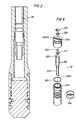
- a firing system adapted for use with a perforating gun, is illustrated.
- the perforating gun is adapted to be disposed in a wellbore.
- a first housing 10 is threadedly connected to a second housing 12; however, a tie wrap 14 prevents the second housing 12 from approaching and contacting the first housing 10 as long as the tie wrap 14 is in place as shown in figure 1.
- the tie wrap 14 is a safe-arm device. It can easily be removed from its location shown in figure 1; and, when the tie wrap 14 is removed, the second housing 12 can be moved toward the first housing 10 thereby allowing the tip 12a of the second housing 12 to contact the tip 10a of the first housing 10. When the tips 12a/10a of the first and second housings 10 and 12 contact each other, the firing system of figures 1-2 is armed.
- a detonating cord 16 and a wireline cable 18 are disposed adjacent one another within the interior of the first and second housings 10 and 12.
- the wireline cable 18 runs, at its top end, to the surface of the wellbore; and the detonating cord 16 is connected, at its top end, to a plurality of shaped charges in the perforating gun the detonating the shaped charges in a bottom-up firing sequence.
- the detonating cord 16 is connected, at its bottom end, to a booster 16a.
- the wireline cable 18 is disposed within a housing 20 which encloses the booster 16a of the detonating cord 16 and is further connected, at its bottom end, to a firing head 22 in accordance with the present invention.
- the booster 16a ignites and detonates which initiates the propagation of a detonation wave in the detonating cord 16.
- the detonation wave begins to propagate upwardly through the detonating cord 16 to the plurality of shaped charges in the perforating gun.
- the shaped charges of the perforating gun are disposed above the firing head 22 in figure 1 (a bottom-up configuration); therefore the shaped charges detonate from bottom to top as described in the background section of this specification.
- a jet is formed from each shaped charge, starting with the lowermost shaped charge and ending with the uppermost shaped charge.
- the jets perforate a formation traversed by the wellbore, starting with a lowermost part of the formation and ending with an uppermost part of the formation.
- Well fluid begins to flow from the perforated formation.
- a power supply or fire set circuit 24 is electrically connected to the firing head 22.
- the fire set circuit 24 receives its energizing current from the wireline cable 18.
- a wireline current conducting in the wireline cable 18 energizes the fire set circuit 24 and, in response, the fire set circuit 24 provides the high energy discharge pulse to the firing head 22.
- the firing head 22 ignites and detonates the booster 16a as described above.
- Figure 3 illustrates a cross section of figure 1 taken along section lines 3-3 of figure 1.
- FIG 4 a three dimensional view of the firing head 22 of figure 1 is illustrated.
- the firing head 22 comprises an outer pressure bulkhead housing 22a and a pin 22b disposed within the interior of the pressure bulkhead 22a.
- an EFI bridge disposed on top of the pin 22b
- an EFI barrel disposed on top of the EFI bridge
- a secondary (HE) explosive disposed on top of the EFI barrel.
- the first current flowing in the pressure bulkhead 22a is the wireline current 18a conducting from the wireline cable 18, and the second current flowing in the pressure bulkhead 22a is the EFI return current 24a to EFI ground.
- the EFI ground potential is the same potential as to wireline power and is also floating in respect to all other potentials and, in particular, to tool ground.
- the EFI return current 24a is the return current to ground potential from an exploding foil initiator (EFI) which is disposed on the top of pin 22b.
- EFI exploding foil initiator
- An EFI current 24b originating from the fire set circuit 24 propagates upwardly through the pin 22b and moves toward to the top of the pin 22b where it energizes the EFI disposed on the top of the pin 22b.
- the EFI return current flows out of the EFI, into the outer pressure bulkhead housing 22a, and down the sides of the pressure bulkhead housing 22a to ground potential.
- wireline current 18a from wireline 18 flows down the sides of the pressure bulkhead housing 22a, and out the pressure bulkhead 22a on its way toward the fire set circuit 24.
- the housing 22a Due to the geometry (size, shape, volume) of the pressure bulkhead housing 22a, the housing 22a exhibits a low effective series resistance and a low effective series inductance. As a result, the pressure bulkhead 22a will easily conduct a rapid high energy discharge pulse from the fire set circuit 24.
- FIG 5 an exploded view of the firing head 22 of figure 4 is illustrated.
- the outer pressure bulkhead housing 22a encloses the pin 22b.
- the pin 22b is made of stainless steel (an electrically conductive material); however, substantially the entire surface area of the pin 22b is coated with a polyamide based insulating material 22b3 known as "PYRL-ML" manufactured by E.I. Dupont DeNemours (Dupont) Corporation.
- PYRL-ML insulating coating 22b3 covers the entire surface area of the pin 22b except for: (1) one circular area 22b1 disposed on the top of the pin 22b, and (2) the bottom 22b2 surface area of the pin.
- the circular area 22b1 on the top of the pin 22b appears to be a dot; however, the dot actually represents a conductive pad area for conducting an electrical current from the pin 22b.
- the bottom 22b2 surface area of the pin 22b is not coated with the PYRL-ML insulating coating 22b3 because the bottom surface area 22b2 of pin 22b is plugged into a female electrical connector which conducts a high energy discharge pulse to the pin 22b from the fire set circuit 24.
- An EFI bridge 22c is disposed on the top of the pin 22b. The exact orientation of the EFI bridge 22c on the top of pin 22b is important, this orientation being discussed with reference to figure 6 of the drawings.
- the outer pressure bulkhead housing 22a includes a top ground cap 22a1.
- a center bore 22a1A is disposed through the center of the ground cap 22a1, and a secondary explosive in the form of a cylindrical pellet 22e (the secondary explosive being HE) fits snugly within the center bore 22a1A of the ground cap 22a1.
- a metal flyer 22f is disposed above the secondary explosive pellet 22e.
- a flying plate is cut from the center of the flyer 22f, the flying plate flying across a space and impacting the booster 16a of the detonating cord 16 in figure 1 thereby initiating the propagation of a detonation wave in the detonating cord 16.
- the shaped charges in a perforating gun will detonate in response to the detonation wave.
- O-rings 22g and 22h seal the pin and bulkhead thereby preventing fluid invasion beyond the bulkhead.
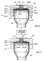
- FIG 6 an enlarged three dimensional view of the pin 22b, EFI bridge 22c, EFI barrel 22d, ground cap 22a1, secondary explosive pellet 22e and flyer 22f of figure 5 is illustrated.
- the pin 22b is coated with the PYRL-ML insulating coating 22b3 of figure 5 except for a conductive pad area 22b1 disposed on the top of the pin 22b and the bottom surface area 22b2 on the bottom of the pin. Since the pin 22b is made of stainless steel, it can easily conduct an electrical current. The current is provided by the fire set circuit 24 which provides a high energy discharge pulse, the discharge pulse conducting from the bottom surface area 22b2, up the centre part of the pin 22b, and toward the conductive pad area 22b1.
- the EFI bridge 22c is comprised of three layers, a first layer 22c1, a second layer 22c2, and a third layer 22c3.
- the first layer 22c1 is 0.025mm (1 mil) in thickness and is comprised of a polyimide material.
- a polyimide material to use for the first layer 22c1 is a material known as "Kapton".
- the Kapton polyimide material is manufactured by E.I. Dupont De Nemours, Incorporated (Dupont).
- the first layer 22c1 includes a hole 22c1A which is filled with a conductive epoxy in order to facilitate the conductance of an electrical current (the high energy discharge pulse from the fire set circuit 24) from the pin 22b, into the conductive pad area 22b1, and into the conductive epoxy which fills the hole 22c1A of the first layer 22c1.
- the second layer 22c2 of the EFI bridge 22c is approximately 0.0043mm (170 micro-inch) in thickness, is comprised of a Copper material, and is electroplated to the first layer 22c1.
- the Copper material of the second layer 22c2 is an electrically conductive material and was selected to receive the high energy discharge pulse, from the conductive epoxy in the hole 22c1A, into a first left hand portion of the copper second layer 22c2 and to further conduct the pulse through a centre neck section 22c2A of the copper second layer 22c2 toward a second right hand portion of the copper second layer 22c2 where a crescent conductive pad area 22c2B is disposed.
- the crescent conductive pad area 22c2B on the second layer 22c2 of the EFI bridge 22c is electrically connected to a conductive epoxy which is disposed within a hole 22c3A of the third layer 22c3 of the EFI bridge 22c, the conductive epoxy in the hole 22c3A being electrically connected to a shoulder X which is disposed around an interior of the ground cap 22a1 of the outer pressure bulkhead housing 22a.
- the high energy discharge pulse from the second right hand portion of the copper second layer 22c2 conducts into the crescent conductive pad area 22c2B and eventually conducts through the conductive epoxy in the hole 22c3A and into the ground cap 22a1 of the outer pressure bulkhead housing 22a.
- the third layer 22c3 of the EFI bridge 22c is 0.025mm (1 mil) in thickness and is comprised of the Kapton polyimide material.
- the third layer 22c3 includes the hole 22c3A, in which a conductive epoxy is disposed, which has a shape which conforms to the shape of the crescent conductive pad 22c2B of the second layer 22c2.
- the EFI barrel 22d is actually a spacer layer made of a polyamide material.
- the EFI barrel 22d is 0.25mm (0.010 inches) in thickness and is 6.4mm (0.25 inches) in diameter and includes a hole 22d1 which is 1.4mm (0.055 inches) in diameter and is 0.25mm (0.010 inches) in height.
- the outer pressure bulkhead housing 22a includes the ground cap 22a1 which is disposed above the EFI barrel 22d.
- the ground cap 22a1 includes a centre bore in which a secondary explosive (HE) pellet 22e is disposed.
- the pellet 22e is positioned directly above the hole 22d1 in the EFI barrel 22d and directly above the neck section 22c2A of the copper second layer 22c2 of the EFI bridge 22c.
- the flyer 22f is disposed directly above the ground cap 22a1.
- FIG 7 a top view of the second layer 22c2 and the third layer 22c3 of the EFI bridge 22c of figures 5 and 6 is illustrated. Note how the crescent conductive pad area 22c2B is electrically connected to a conductive epoxy disposed within the hole 22c3A in the third layer 22c3 and how the conductive epoxy in hole 22c3A is electrically connected to the shoulder X of the outer pressure bulkhead housing 22a.
- FIG 8 a top view of the first layer 22c1 of the EFI bridge 22c is illustrated. Note the hole 22c1A in the first layer 22c1. As noted earlier, the hole 22c1A is filled with a conductive epoxy 22c1B in order to facilitate the conductance of the discharge pulse from the fire set circuit 24, through the pin 22b, the conductive pad area 22b1 and the epoxy 22c1B to the second layer 22c2 of the EFI bridge 22c.
- FIG 9 the geometry associated with the neck section 22c2A of the second layer 22c2 of the EFI bridge 22c, before the neck section has vaporized in response to the discharge pulse from the fire set circuit 24, is illustrated.
- the first left hand portion 22c2C of the second layer 22c2 is integrally connected to the neck section 22c2A, the neck section being integrally connected to the second right hand portion 22c2D of the second layer 22c2.
- the neck section vaporizes and disappears.
- Figure 9 illustrates the neck section 22c2A of the second layer 22c2 of the EFI bridge 22c before the neck section vaporized and disappeared as a result of the discharge pulse current passing through neck section.
- the barrel 22d has a hole 22d1 disposed through its center, the hole guiding and forming a bubble from the third layer 22c3 during the passage of the bubble through the hole 22d1 toward the secondary explosive pellet 22e.
- the barrel 22d includes a notch 22d2.
- the notch 22d2 is needed to allow pressure to be applied to the top of the conductive pad area 22b1, via the conductive epoxy in hole 22c1A, during attachment of the EFI to the pin 22b.
- the EFI bridge 22c includes a first layer 22c1, a second layer 22c2 and a third layer 22c3.
- the first layer 22c1A includes a hole 22c1A
- the third layer 22c3 has a hole 22c3A which corresponds to the shape of the crescent shaped conductive pad 22c2B of the second layer 22c2 of the EFI bridge 22c.
- the hole 22c3A in the third layer 22c3 allows the crescent pad 22c2B to electrically contact the shoulder X of the ground cap 22a1 of the outer pressure bulkhead housing 22a via the conductive epoxy in hole 22c3A.
- the top of pin 22b is illustrated
- the top part of pin 22b is coated with a PYRL-ML insulating coating 22b3, where the PYRL-ML polyamide based dielectric insulating coating is manufactured by Dupont Corporation.
- a small portion 22b1 of the top part of pin 22b is not coated with the insulating coating 22b3 thereby allowing the electrically conductive material (stainless steel) of the pin 22b to show therethrough, this small portion 22b1 forming a dot, the dot representing an electrically conductive pad area 22b1 for conducting an electrical current.
- the pin 22b is coated on its sides (but not on its bottom 22b2) with the PYRL-ML insulating coating 22b3.
- the pin 22b itself (without the coating) is made of an electrically conductive stainless steel material; however, substantially the entire surface area is coated with the insulating coating 22b3 except for the bottom 22b2 (which is adapted to be connected to an electrical connector) and the dot conductive pad area 22b1 disposed on the top of the pin.
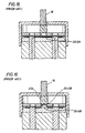
- FIG 14 a longitudinal cross sectional view of the firing head 22 shown in figure 6 is illustrated in a state which exists prior to detonation of the exploding foil initiator (EFI) in the firing head 22.
- EFI exploding foil initiator
- the discharge pulse 24b from the fire set circuit 24 passes through the center of the pin 22b.
- An insulating coating 22b3 coats substantially the entire surface area of the pin; however, a hole in the coating exposes a conductive pad area 22b1.
- the discharge pulse 24b passes through the conductive pad area 22b1, through the conductive epoxy in the hole 22c1A in the first layer 22c1 of the EFI bridge 22c, and into the second layer 22c2 of the EFI bridge 22c.
- the discharge pulse current 24b propagates from the left hand portion 22c2C of the second layer 22c2 of the EFI bridge 22c, through the neck section 22c2A, and toward the right hand portion 22c2D of the second layer (see figure 9).
- the current which emerges from the neck section 22c2A of the second layer 22c2 of the EFI bridge 22c is now called the EFI return current 24a.
- the EFI return current 24a propagates from the right hand portion 22c2D of the second layer 22c2 into the crescent conductive pad area 22c2B disposed on the second layer, the EFI return current 24a continuing to propagate from the crescent conductive pad area 22c2B into the ground cap 22a1 of the outer pressure bulkhead housing 22a.
- the EFI return current 24a propagates from the ground cap 22a1 down the sides of the outer pressure bulkhead housing 22a to ground potential in the manner shown in figures 4 and 6 of the drawings.
- FIG 17 a longitudinal cross sectional view of the firing head 22 shown in figure 6 is illustrated in a state which exists after detonation of the exploding foil initiator (EFI bridge 22c) in the firing head 22.
- EFI bridge 22c exploding foil initiator
- the flying plate 22f1 impacts the booster 16a of the detonating cord 16 in figure 1 detonating the booster and initiating the propagation of a detonation wave in the detonating cord 16.
- the detonation wave detonates all the shaped charges in the perforating gun situated above the firing head 22.
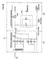
- the fire set circuit 24 includes a transformer coupled floating ground fullwave rectifier 24a and a discharge subassembly 24b.
- the transformer allows the output ground to be isolated in respect to all other potentials and is therefore the key for allowing the wireline current to become common with the EFI return current.
- the fullwave rectifier 24a receives a high frequency AC voltage from the wireline 18 via an inverter section and converts the AC wireline voltage into a direct current (DC) voltage by full wave rectifying.
- the DC voltage output from the fullwave rectifier portion 24a generates a DC current which charges a capacitor 24b1 in the discharge subassembly 24b.
- a gas discharge tube 24b2 known as an overvoltage gap, which functions like a switch, conducts thereby allowing the current in the charged capacitor 24b1 to pass through the gas discharge tube 24b2.
- the current passing through the gas discharge tube 24b2 represents the high energy discharge pulse current 24b which conducts through the pin 22b of the firing head 22 and eventually passes through the neck section 22c2A of the EFI bridge 22c thereby vaporizing the neck section of the bridge.
- vaporization of the neck section 22c2A causes a bubble 22c3B to form in the third layer 22c3 of the EFI bridge 22c, the bubble being formed and shaped by the hole 22d1 in the EFI barrel 22d prior to impacting the secondary explosive pellet 22e.
- the pellet 22e When the pellet 22e is impacted, it detonates, and detonation of the pellet 22e causes a flying plate 22f1 to shear out of the flyer 22f and fly across a space impacting the booster of detonating cord 16.
- the tie wrap 14 is a safe arm device. That is, prior to removal of the tie wrap 14, the second housing 12 cannot move toward the first housing 10; and, as a result, the ground cap 22a1 of the outer pressure bulkhead housing 22a of the firing head 22 is spaced from the flyer 22f by a distance 30. Therefore, if the firing head 22 accidentally detonates, due to the distance 30, detonation of the secondary explosive pellet 22e will not shear out a flying plate 22f1 from the flyer 22f (see figure 6).
- the safe arm tie wrap device 14 When it is time to perforate a formation traversed by a wellbore, the safe arm tie wrap device 14 must be removed. The tie wrap 14 is removed. When the tie wrap 14 is removed, the second housing 12 is moved toward the first housing 10 of the firing system in figure 1. When the second housing 12 moves toward the first housing 10, the distance 30 is closed and the secondary explosive pellet 22e disposed within the ground cap 22a1 of the outer pressure bulkhead housing 22a of the firing head 22 approaches and ultimately contacts the flyer 22f. When the ground cap 22a1 contacts the flyer 22f, the firing head 22 in the firing system of figure 1 is armed and is ready to fire.
- wireline current 18a When an operator at a surface of the wellbore wants to fire the firing system of figures 1-2 and detonate a perforating gun in the wellbore, an electrical signal is transmitted down the wireline 18 into the wellbore.
- the signal hereinafter known as wireline current 18a, propagates down the wireline 18, through the housing 20 which encloses booster 16a, through the outer pressure bulkhead housing 22a of the firing head 22 as shown in figures 4 and 6, and energizes the fire set circuit 24 in figures 6 and 18.
- the fullwave rectifier 24a changes the inverter high frequency wireline current 18a into a DC voltage which is input to the discharge subassembly 24b in figure 18.
- the DC voltage charges the capacitor 24b1.
- the gas discharge tube 24b2 goes into rapid conduction.
- a current rapidly flows from the capacitor 24b1, through the gas discharge tube 24b2, and energizes the pin 22b of the firing head 22, this current, energizing the pin 22b, hereinafter being known as the EFI current 24b or the high energy discharge pulse 24b.
- the discharge pulse or EFI current 24b energizes the pin 22b, travels up the center of the pin 22b, crosses over to the outer pressure bulkhead housing 22a, emerging as an EFI return current 24a, and propagates down the sides of the outer pressure bulkhead housing 22a to ground potential.
- the discharge pulse 24b propagates up the center of pin 22b and propagates through the conductive pad area 22b1 since the insulating coating 22b3 covers substantially the entire surface area of the pin 22b except for the conductive pad area 22b1 and the bottom 22b2.
- the discharge pulse 24b propagates through the conductive epoxy in hole 22c1A of the first layer 22c1, and conducts into the second layer 22c2 of the EFI bridge 22c.
- the discharge pulse or EFI current 24b propagates from the left hand portion 22c2C to the right hand portion 22c2D of the second layer 22c2 (see figure 9) via the neck section 22c2A of the second layer 22c2.
- the current which emerges from the neck section Prior to vaporization of the neck section 22c2A, the current which emerges from the neck section, now known as the EFI return current 24a, conducts through the crescent shaped conductive pad 22c2B on the second layer 22c2, through the crescent shaped hole 22c3A in the third layer 22c3 via conductive epoxy, and conducts into the ground cap 22a1 of the outer pressure bulkhead housing 22a of the firing head 22 via shoulder X.
- the EFI return current 24a propagating within the outer pressure bulkhead housing 22a, then flows to the edge of the ground cap 22a1 and flows, within the pressure bulkhead, down the side of the pressure bulkhead 22a to ground potential in the manner shown in figures 4,6, and 14 of the drawings.
- two separate and distinct currents flow simultaneously within the outer pressure bulkhead housing 22a of the firing head 22: the wireline current 18a and the EFI return current 24a.
- the flying plate 22f1 impacts the booster 16a of detonating cord 16 initiating the propagation of a detonation wave in the detonating cord 16.
- the detonation wave propagates up the detonating cord 16 in figure 1 detonating the shaped charges in the perforating gun.
Landscapes
- Engineering & Computer Science (AREA)
- General Engineering & Computer Science (AREA)
- Life Sciences & Earth Sciences (AREA)
- Geology (AREA)
- Mining & Mineral Resources (AREA)
- Physics & Mathematics (AREA)
- Environmental & Geological Engineering (AREA)
- Fluid Mechanics (AREA)
- General Life Sciences & Earth Sciences (AREA)
- Geochemistry & Mineralogy (AREA)
- Air Bags (AREA)
Claims (11)
- Système de mise à feu adapté à être disposé dans un outil de forage pour faire détoner un dispositif, ledit système comprenant :des moyens générateurs de signal de décharge (24) sensibles à un signal d'activation (18a) pour produire un signal de décharge (24b) ; etdes moyens de mise à feu (22) sensibles au signal de décharge (24b) pour faire détoner un explosif (22e) et produire un signal de retour ;caractérisé en ce que ledit signal d'activation (18a) est un signal alternatif et ledit signal de décharge (24b) est un signal continu, et lesdits moyens de mise à feu (22) comportent des moyens formant boîtier extérieur (20) qui sont utilisés pour conduire ledit signal d'activation (18a) vers lesdits moyens générateurs de signal de décharge (24) et pour conduire le signal de retour (24a) desdits moyens de mise à feu (22) jusqu'à un potentiel de terre, et
des moyens de détonation sensibles à la détonation dudit explosif pour faire détoner ledit dispositif. - Système de mise à feu selon la revendication 1, dans lequel ledit signal d'activation (18a) comprend un signal de câble (18a) adapté à être transmis le long d'un câble (18) audit dispositif de forage lorsque ledit dispositif de forage est disposé dans ledit trou de forage, et dans lequel lesdits moyens générateurs de signal de décharge (24) comprennent des moyens redresseurs (24a) pour redresser ledit signal de câble (18a) afin de produire ainsi un signal de sortie redressé, lesdits moyens redresseurs comprenant :un transformateur de sortie de ligne à haute tension T2 adapté à isoler ledit potentiel de terre pour ledit signal de retour d'autres potentiels et faire en sorte qu'un potentiel dudit signal de câble soit commun audit potentiel de terre pour ledit signal de retour ;des moyens (24b1) de stockage de charge sensibles audit signal de sortie redressé pour stocker une charge ;des moyens (24b2) de commutation pour basculer entre une position ouverte et une position fermée ; etdes moyens conducteurs pour conduire un courant depuis lesdits moyens de stockage de charge (24b1) lorsque lesdits moyens de commutation (24b2) basculent sur ladite position fermée, ledit courant étant ledit signal de décharge (24b).
- Système de mise à feu selon la revendication 1 ou la revendication 2, dans lequel lesdits moyens de mise à feu (22) comprennent des moyens d'amorçage disposés à l'intérieur desdits moyens formant boîtier extérieur (20) et sensibles audit signal de décharge (24b) pour produire une bulle, ladite bulle produisant un impact sur ledit explosif (22e), ledit explosif (22e) détonnant en réponse à l'impact.
- Système de mise à feu selon la revendication 3, dans lequel lesdits moyens d'amorçage (22) comprennent :une broche conductrice (22b) disposée à l'intérieur desdits moyens formant boîtier extérieur (20) et adaptée à conduire ledit signal de décharge (24b) provenant desdits moyens générateurs de signal de décharge (24) ; etun matériau isolant (22b3) adhérant sensiblement à toute la superficie de ladite broche (22b), ledit matériau isolant (22b3) définissant une zone formant plage électriquement conductrice (22b1) sur une partie de ladite broche (22b) où ledit matériau isolant (22b3) n'est pas disposé, ladite zone formant plage conductrice (22b1) étant adaptée à conduire ledit signal de décharge (24b).
- Système de mise à feu selon la revendication 4, dans lequel lesdits moyens d'amorçage (22) comprennent :des moyens d'amorçage à feuille explosive (22c) électriquement connectés à ladite zone formant plage conductrice (22b1) et sensibles audit signal de décharge (24b) pour produire ledit signal de retour (24a) et créer une turbulence ; etdes moyens à couche de polyimide (22c3) disposés sur lesdits moyens d'amorçage à feuille explosive (22c) afin de se dilater et de former ladite bulle en réponse à ladite turbulence, ladite bulle produisant un impact sur ledit explosif (22e), ledit explosif (22e) détonant en réponse à l'impact.
- Système de mise à feu selon la revendication 5, dans lequel lesdits moyens d'amorçage à feuille explosive (22c) comprennent :une feuille conductrice ayant une première zone plane (22c2) électriquement connectée à ladite zone formant plage conductrice (22b1) de ladite broche (22b) et sensible audit signal de décharge (24b), une seconde zone plane (22c2B), et une section étranglée (22c2A) connectée de façon intégrale à ladite première zone plane (22c2) et à ladite seconde zone plane (22c2B) ;ledit signal de décharge (24b) se propageant électriquement de ladite première zone plane (22c2), en passant par ladite section étranglée (22c2A), à ladite seconde zone plane (22c2B), de sorte que ledit signal de décharge (24b) dans ladite seconde zone plane (22c2B) constitue ledit signal de retour (24a), et ladite section étranglée (22c2A) se vaporisant en réponse audit signal de décharge (24b) afin de créer ladite turbulence.
- Outil de forage comportant un système de mise à feu selon l'une quelconque des revendications précédentes, ledit outil comprenant également une charge creuse et un cordon détonant fonctionnellement relié entre ledit explosif (22e) et ladite charge creuse.
- Procédé pour faire fonctionner un système de mise à feu dans un dispositif de forage lorsque ledit dispositif de forage est disposé dans un trou de forage, ledit système de mise à feu comprenant une tête de mise à feu (22) contenant un explosif (22e) et ayant un boîtier extérieur (20), le procédé comprenant les étapes :(a) de transmission d'un signal d'activation (18a) à un circuit (24) ;(b) en réponse audit signal d'activation (18a), de transmission d'un signal de décharge (24b) à partir dudit circuit (24) pour faire détonner ledit explosif (22e) dans ladite tête de mise à feu (22) ;caractérisé en ce que ledit signal d'activation (18a) est un signal alternatif et ledit signal de décharge (24b) est un signal continu, et en ce que ledit signal d'activation (18a) et le signal de retour (24b) provenant dudit circuit (24), sont tous deux conduits par l'intermédiaire dudit boîtier extérieur (20) de ladite tête de mise à feu (22).
- Procédé selon la revendication 8, dans lequel ledit signal d'activation (18a) est un signal de courant de câble (18a) adapté à être conduit le long d'un câble lorsque ledit dispositif de forage est disposé dans ledit trou de forage, l'étape de transmission (a) comprenant l'étape de transmission dudit signal de courant de câble (18a) le long dudit câble jusqu'à ladite tête de mise à feu (22) dans ledit dispositif de forage.
- Procédé selon la revendication 9, dans lequel l'étape de transmission (b) comprend les étapes :en réponse audit signal de courant de câble (18a), de transmission d'une impulsion de décharge (24b) dudit circuit (24) à ladite tête de mise à feu (22) ; etde conduction de ladite impulsion de décharge (24b) à travers une première zone plane (22c2) d'une feuille, à travers une section d'étranglement (22c2A) de ladite feuille, et à l'intérieur d'une seconde zone plane (22c2B) de ladite feuille, l'impulsion de décharge dans ladite seconde zone plane (22c2B) étant ledit signal de retour (24a).
- Procédé selon la revendication 10, dans lequel une couche de polyimide (22c3) est disposée sur ladite feuille, et comprenant les étapes :lorsque ladite impulsion de décharge (24b) est conduite à travers ladite section étranglée (22c2A) de ladite feuille, de dilatation d'une partie de ladite couche de polyimide (22c3) afin de former une bulle ; etde production par ladite bulle d'un impact sur ledit explosif (22c), ledit explosif (22e) détonant en réponse à l'impact de ladite bulle.
Applications Claiming Priority (2)
| Application Number | Priority Date | Filing Date | Title |
|---|---|---|---|
| US08/116,082 US5347929A (en) | 1993-09-01 | 1993-09-01 | Firing system for a perforating gun including an exploding foil initiator and an outer housing for conducting wireline current and EFI current |
| US116082 | 1993-09-01 |
Publications (3)
| Publication Number | Publication Date |
|---|---|
| EP0651229A2 EP0651229A2 (fr) | 1995-05-03 |
| EP0651229A3 EP0651229A3 (fr) | 1995-11-02 |
| EP0651229B1 true EP0651229B1 (fr) | 1997-10-15 |
Family
ID=22365123
Family Applications (1)
| Application Number | Title | Priority Date | Filing Date |
|---|---|---|---|
| EP94401941A Expired - Lifetime EP0651229B1 (fr) | 1993-09-01 | 1994-09-01 | Dispositif d'allumage pour un perforateur comportant un détonateur avec une feuille explosive |
Country Status (3)
| Country | Link |
|---|---|
| US (1) | US5347929A (fr) |
| EP (1) | EP0651229B1 (fr) |
| DE (1) | DE69406242D1 (fr) |
Cited By (1)
| Publication number | Priority date | Publication date | Assignee | Title |
|---|---|---|---|---|
| US8359977B2 (en) | 2008-12-27 | 2013-01-29 | Schlumberger Technology Corporation | Miniature shaped charge for initiator system |
Families Citing this family (88)
| Publication number | Priority date | Publication date | Assignee | Title |
|---|---|---|---|---|
| US5505134A (en) * | 1993-09-01 | 1996-04-09 | Schlumberger Technical Corporation | Perforating gun having a plurality of charges including a corresponding plurality of exploding foil or exploding bridgewire initiator apparatus responsive to a pulse of current for simultaneously detonating the plurality of charges |
| US5444598A (en) * | 1993-09-29 | 1995-08-22 | Raymond Engineering Inc. | Capacitor exploding foil initiator device |
| US5436791A (en) * | 1993-09-29 | 1995-07-25 | Raymond Engineering Inc. | Perforating gun using an electrical safe arm device and a capacitor exploding foil initiator device |
| DE4415388C1 (de) * | 1994-05-02 | 1995-04-20 | Euro Matsushita Electric Works | Sprengkette |
| US5969286A (en) * | 1996-11-29 | 1999-10-19 | Electronics Development Corporation | Low impedence slapper detonator and feed-through assembly |
| AU2342700A (en) | 1998-09-24 | 2000-04-26 | Schlumberger Technology Corporation | Detonators for use with explosive devices |
| US6752083B1 (en) | 1998-09-24 | 2004-06-22 | Schlumberger Technology Corporation | Detonators for use with explosive devices |
| US6938689B2 (en) | 1998-10-27 | 2005-09-06 | Schumberger Technology Corp. | Communicating with a tool |
| US6148263A (en) * | 1998-10-27 | 2000-11-14 | Schlumberger Technology Corporation | Activation of well tools |
| US7383882B2 (en) * | 1998-10-27 | 2008-06-10 | Schlumberger Technology Corporation | Interactive and/or secure activation of a tool |
| US7347278B2 (en) * | 1998-10-27 | 2008-03-25 | Schlumberger Technology Corporation | Secure activation of a downhole device |
| US6283227B1 (en) | 1998-10-27 | 2001-09-04 | Schlumberger Technology Corporation | Downhole activation system that assigns and retrieves identifiers |
| US7336474B2 (en) * | 1999-09-23 | 2008-02-26 | Schlumberger Technology Corporation | Microelectromechanical devices |
| US6389975B1 (en) | 2000-04-24 | 2002-05-21 | The United States Of America As Represented By The Secretary Of The Navy | Transistorized high-voltage circuit suitable for initiating a detonator |
| FR2811749B1 (fr) * | 2000-07-13 | 2003-03-07 | Tda Armements Sas | Initiateur electro-pyrotechnique securise a haute energie |
| US8770301B2 (en) | 2001-09-10 | 2014-07-08 | William T. Bell | Explosive well tool firing head |
| US8136439B2 (en) * | 2001-09-10 | 2012-03-20 | Bell William T | Explosive well tool firing head |
| US8091477B2 (en) * | 2001-11-27 | 2012-01-10 | Schlumberger Technology Corporation | Integrated detonators for use with explosive devices |
| GB2395502B (en) * | 2002-11-22 | 2004-10-20 | Schlumberger Holdings | Providing electrical isolation for a downhole device |
| US7191706B2 (en) | 2003-09-30 | 2007-03-20 | The Regents Of The University Of California | Optically triggered fire set/detonator system |
| DE602005024757D1 (de) * | 2004-11-30 | 2010-12-30 | Weatherford Lamb | Nicht-explosiver Zweikomponenteninitiator |
| US7762172B2 (en) * | 2006-08-23 | 2010-07-27 | Schlumberger Technology Corporation | Wireless perforating gun |
| US7980309B2 (en) * | 2008-04-30 | 2011-07-19 | Halliburton Energy Services, Inc. | Method for selective activation of downhole devices in a tool string |
| CN101302928B (zh) * | 2008-07-08 | 2012-06-13 | 中国石化集团胜利石油管理局测井公司 | 油管输送射孔电能安全引爆系统 |
| US8276516B1 (en) * | 2008-10-30 | 2012-10-02 | Reynolds Systems, Inc. | Apparatus for detonating a triaminotrinitrobenzene charge |
| US8485097B1 (en) * | 2010-06-11 | 2013-07-16 | Reynolds Systems, Inc. | Energetic material initiation device |
| US8695506B2 (en) | 2011-02-03 | 2014-04-15 | Baker Hughes Incorporated | Device for verifying detonator connection |
| US9677365B2 (en) * | 2014-08-26 | 2017-06-13 | Richard F. Tallini | Radial conduit cutting system and method |
| US8919236B2 (en) | 2012-10-09 | 2014-12-30 | William T. Bell | Perforating gun drop sub |
| US9702680B2 (en) | 2013-07-18 | 2017-07-11 | Dynaenergetics Gmbh & Co. Kg | Perforation gun components and system |
| US12203350B2 (en) | 2013-07-18 | 2025-01-21 | DynaEnergetics Europe GmbH | Detonator positioning device |
| WO2015028204A2 (fr) * | 2013-08-26 | 2015-03-05 | Dynaenergetics Gmbh & Co. Kg | Perforateur et ensemble détonateur |
| US10188990B2 (en) | 2014-03-07 | 2019-01-29 | Dynaenergetics Gmbh & Co. Kg | Device and method for positioning a detonator within a perforating gun assembly |
| WO2015179787A1 (fr) | 2014-05-23 | 2015-11-26 | Hunting Titan, Inc. | Système perforateur à filetage femelle-mâle et procédés associés |
| US10273788B2 (en) | 2014-05-23 | 2019-04-30 | Hunting Titan, Inc. | Box by pin perforating gun system and methods |
| US20150345922A1 (en) * | 2014-05-28 | 2015-12-03 | Baker Hughes Incorporated | Igniter for Downhole Use Having Flame Control |
| CA2955262C (fr) * | 2014-08-29 | 2018-10-16 | Hunting Titan, Inc. | Ensemble explosif a haute tension permettant des detonations de fond de trou |
| US10267605B1 (en) * | 2014-09-30 | 2019-04-23 | Reynolds Systems, Inc. | High G-force resistant initiator assembly having an exploding foil initiator |
| US11293736B2 (en) | 2015-03-18 | 2022-04-05 | DynaEnergetics Europe GmbH | Electrical connector |
| US9784549B2 (en) | 2015-03-18 | 2017-10-10 | Dynaenergetics Gmbh & Co. Kg | Bulkhead assembly having a pivotable electric contact component and integrated ground apparatus |
| DE102015009576B3 (de) * | 2015-07-23 | 2016-08-11 | TDW Gesellschaft für verteidigungstechnische Wirksysteme mbH | Zündvorrichtung |
| WO2017082888A1 (fr) * | 2015-11-11 | 2017-05-18 | Halliburton Energy Services, Inc. | Réutilisation d'énergie électromagnétique provenant d'un convertisseur de tension en fond de trou |
| CA3070124C (fr) | 2015-11-12 | 2022-03-01 | Hunting Titan, Inc. | Ensemble cartouche de piston de contact |
| WO2018034671A1 (fr) * | 2016-08-19 | 2018-02-22 | Halliburton Energy Services, Inc. | Utilisation d'explosifs actionnés électriquement en fond de trou |
| US10914145B2 (en) | 2019-04-01 | 2021-02-09 | PerfX Wireline Services, LLC | Bulkhead assembly for a tandem sub, and an improved tandem sub |
| US10472937B2 (en) | 2017-04-06 | 2019-11-12 | Halliburton Energy Services, Inc. | Assembly for wellbore perforation |
| US10161733B2 (en) | 2017-04-18 | 2018-12-25 | Dynaenergetics Gmbh & Co. Kg | Pressure bulkhead structure with integrated selective electronic switch circuitry, pressure-isolating enclosure containing such selective electronic switch circuitry, and methods of making such |
| US10365079B2 (en) * | 2017-11-01 | 2019-07-30 | Baker Hughes, A Ge Company, Llc | Igniter and ignition device for downhole setting tool power charge |
| US10673161B1 (en) * | 2018-04-23 | 2020-06-02 | Acacia Communications, Inc. | Conductive connector |
| US11021923B2 (en) | 2018-04-27 | 2021-06-01 | DynaEnergetics Europe GmbH | Detonation activated wireline release tool |
| US10458213B1 (en) | 2018-07-17 | 2019-10-29 | Dynaenergetics Gmbh & Co. Kg | Positioning device for shaped charges in a perforating gun module |
| CN108894757B (zh) * | 2018-06-06 | 2020-04-28 | 南京理工大学 | 一种电磁驱动石油射孔弹装置 |
| US10386168B1 (en) | 2018-06-11 | 2019-08-20 | Dynaenergetics Gmbh & Co. Kg | Conductive detonating cord for perforating gun |
| US11808093B2 (en) | 2018-07-17 | 2023-11-07 | DynaEnergetics Europe GmbH | Oriented perforating system |
| US11339614B2 (en) | 2020-03-31 | 2022-05-24 | DynaEnergetics Europe GmbH | Alignment sub and orienting sub adapter |
| USD873373S1 (en) | 2018-07-23 | 2020-01-21 | Oso Perforating, Llc | Perforating gun contact device |
| USD877286S1 (en) | 2018-07-23 | 2020-03-03 | Oso Perforating, Llc | Perforating gun contact ring |
| US11994008B2 (en) | 2018-08-10 | 2024-05-28 | Gr Energy Services Management, Lp | Loaded perforating gun with plunging charge assembly and method of using same |
| US10858919B2 (en) * | 2018-08-10 | 2020-12-08 | Gr Energy Services Management, Lp | Quick-locking detonation assembly of a downhole perforating tool and method of using same |
| US11078763B2 (en) * | 2018-08-10 | 2021-08-03 | Gr Energy Services Management, Lp | Downhole perforating tool with integrated detonation assembly and method of using same |
| USD1019709S1 (en) | 2019-02-11 | 2024-03-26 | DynaEnergetics Europe GmbH | Charge holder |
| USD1034879S1 (en) | 2019-02-11 | 2024-07-09 | DynaEnergetics Europe GmbH | Gun body |
| USD1010758S1 (en) | 2019-02-11 | 2024-01-09 | DynaEnergetics Europe GmbH | Gun body |
| US10927627B2 (en) | 2019-05-14 | 2021-02-23 | DynaEnergetics Europe GmbH | Single use setting tool for actuating a tool in a wellbore |
| US12241326B2 (en) | 2019-05-14 | 2025-03-04 | DynaEnergetics Europe GmbH | Single use setting tool for actuating a tool in a wellbore |
| US11578549B2 (en) | 2019-05-14 | 2023-02-14 | DynaEnergetics Europe GmbH | Single use setting tool for actuating a tool in a wellbore |
| US11255147B2 (en) | 2019-05-14 | 2022-02-22 | DynaEnergetics Europe GmbH | Single use setting tool for actuating a tool in a wellbore |
| US11559875B2 (en) | 2019-08-22 | 2023-01-24 | XConnect, LLC | Socket driver, and method of connecting perforating guns |
| CZ310189B6 (cs) | 2019-12-10 | 2024-11-06 | DynaEnergetics Europe GmbH | Hlava rozněcovadla, rozněcovadlo a sestava rozněcovadla |
| WO2021122797A1 (fr) | 2019-12-17 | 2021-06-24 | DynaEnergetics Europe GmbH | Système de perforateur modulaire |
| US11091987B1 (en) | 2020-03-13 | 2021-08-17 | Cypress Holdings Ltd. | Perforation gun system |
| US12084962B2 (en) | 2020-03-16 | 2024-09-10 | DynaEnergetics Europe GmbH | Tandem seal adapter with integrated tracer material |
| USD1041608S1 (en) | 2020-03-20 | 2024-09-10 | DynaEnergetics Europe GmbH | Outer connector |
| US11988049B2 (en) | 2020-03-31 | 2024-05-21 | DynaEnergetics Europe GmbH | Alignment sub and perforating gun assembly with alignment sub |
| USD904475S1 (en) | 2020-04-29 | 2020-12-08 | DynaEnergetics Europe GmbH | Tandem sub |
| USD908754S1 (en) | 2020-04-30 | 2021-01-26 | DynaEnergetics Europe GmbH | Tandem sub |
| US11713625B2 (en) | 2021-03-03 | 2023-08-01 | DynaEnergetics Europe GmbH | Bulkhead |
| WO2022184732A1 (fr) | 2021-03-03 | 2022-09-09 | DynaEnergetics Europe GmbH | Cloison et adaptateur d'étanchéité double |
| US12366142B2 (en) | 2021-03-03 | 2025-07-22 | DynaEnergetics Europe GmbH | Modular perforating gun system |
| US12253339B2 (en) | 2021-10-25 | 2025-03-18 | DynaEnergetics Europe GmbH | Adapter and shaped charge apparatus for optimized perforation jet |
| US12312925B2 (en) | 2021-12-22 | 2025-05-27 | DynaEnergetics Europe GmbH | Manually oriented internal shaped charge alignment system and method of use |
| US12297721B2 (en) | 2021-12-23 | 2025-05-13 | Axis Wireline Technologies, Llc | Reusable perforation gun coupler system |
| WO2023200984A1 (fr) | 2022-04-15 | 2023-10-19 | Dbk Industries, Llc | Outil de réglage à volume fixe |
| US11753889B1 (en) | 2022-07-13 | 2023-09-12 | DynaEnergetics Europe GmbH | Gas driven wireline release tool |
| WO2024013338A1 (fr) | 2022-07-13 | 2024-01-18 | DynaEnergetics Europe GmbH | Outil de libération de câble entraîné par gaz |
| US12359896B2 (en) | 2022-07-29 | 2025-07-15 | DynaEnergetics Europe GmbH | Detonator including a multidimensional circuit board |
| US12509969B2 (en) | 2023-01-11 | 2025-12-30 | Axis Wireline Technologies, Llc | Safe perforation gun system |
| US12546194B2 (en) | 2023-08-04 | 2026-02-10 | DynaEnergetics Europe GmbH | Method and apparatus for automatic arming of perforating gun |
Family Cites Families (11)
| Publication number | Priority date | Publication date | Assignee | Title |
|---|---|---|---|---|
| US3351016A (en) * | 1965-12-10 | 1967-11-07 | Universal Match Corp | Explosive arming and firing system |
| AT283495B (de) * | 1967-07-07 | 1970-08-10 | Schaffler & Co | Kondensatorzündvorrichtung |
| US4788913A (en) * | 1971-06-02 | 1988-12-06 | The United States Of America As Represented By The United States Department Of Energy | Flying-plate detonator using a high-density high explosive |
| US3757697A (en) * | 1972-02-02 | 1973-09-11 | Bendix Corp | Remotely controlled blasting machine |
| US3978791A (en) * | 1974-09-16 | 1976-09-07 | Systems, Science And Software | Secondary explosive detonator device |
| US4471697A (en) * | 1982-01-28 | 1984-09-18 | The United States Of America As Represented By The United States Department Of Energy | Bidirectional slapper detonator |
| US4441427A (en) * | 1982-03-01 | 1984-04-10 | Ici Americas Inc. | Liquid desensitized, electrically activated detonator assembly resistant to actuation by radio-frequency and electrostatic energies |
| US4762067A (en) * | 1987-11-13 | 1988-08-09 | Halliburton Company | Downhole perforating method and apparatus using secondary explosive detonators |
| US4944225A (en) * | 1988-03-31 | 1990-07-31 | Halliburton Logging Services Inc. | Method and apparatus for firing exploding foil initiators over long firing lines |
| US5088413A (en) * | 1990-09-24 | 1992-02-18 | Schlumberger Technology Corporation | Method and apparatus for safe transport handling arming and firing of perforating guns using a bubble activated detonator |
| FR2669725B1 (fr) * | 1990-11-27 | 1994-10-07 | Thomson Brandt Armements | Detonateur pyrotechnique a connexions coaxiales. |
-
1993
- 1993-09-01 US US08/116,082 patent/US5347929A/en not_active Expired - Lifetime
-
1994
- 1994-09-01 EP EP94401941A patent/EP0651229B1/fr not_active Expired - Lifetime
- 1994-09-01 DE DE69406242T patent/DE69406242D1/de not_active Expired - Lifetime
Cited By (1)
| Publication number | Priority date | Publication date | Assignee | Title |
|---|---|---|---|---|
| US8359977B2 (en) | 2008-12-27 | 2013-01-29 | Schlumberger Technology Corporation | Miniature shaped charge for initiator system |
Also Published As
| Publication number | Publication date |
|---|---|
| EP0651229A2 (fr) | 1995-05-03 |
| US5347929A (en) | 1994-09-20 |
| EP0651229A3 (fr) | 1995-11-02 |
| DE69406242D1 (de) | 1997-11-20 |
Similar Documents
| Publication | Publication Date | Title |
|---|---|---|
| EP0651229B1 (fr) | Dispositif d'allumage pour un perforateur comportant un détonateur avec une feuille explosive | |
| US4944225A (en) | Method and apparatus for firing exploding foil initiators over long firing lines | |
| US5088413A (en) | Method and apparatus for safe transport handling arming and firing of perforating guns using a bubble activated detonator | |
| CA2345301C (fr) | Amorcage de dispositifs explosifs | |
| CA2152682C (fr) | Charge creuse a allumage simultane en plusieurs points des explosifs | |
| CA2145740C (fr) | Perforateur de tubage avec charges multiples | |
| US3621916A (en) | Spark-type casing perforator | |
| US5431104A (en) | Exploding foil initiator using a thermally stable secondary explosive | |
| US5436791A (en) | Perforating gun using an electrical safe arm device and a capacitor exploding foil initiator device | |
| US4762067A (en) | Downhole perforating method and apparatus using secondary explosive detonators | |
| EP0601880A2 (fr) | Détonateur pour perforateur de puits avec feuille explosante | |
| US5859383A (en) | Electrically activated, metal-fueled explosive device | |
| CA2880368A1 (fr) | Detonateurs integres pour engins explosifs | |
| CA2412192C (fr) | Detonateur integre pour explosifs | |
| AU654164B2 (en) | Firing arrangements | |
| US2925775A (en) | Well casing perforator | |
| NO338142B1 (no) | Integrerte detonatorer til bruk med eksplosive anordninger | |
| US20040060735A1 (en) | Impulse generator and method for perforating a cased wellbore | |
| GB2290855A (en) | Shaped charge with simultaneous multi-point initiation of explosives | |
| US2334931A (en) | Gun perforator and firing device therefor | |
| US20050183607A1 (en) | Optically triggered fire set/detonator system | |
| EP0561499A1 (fr) | Arrangement d'explosives | |
| CA1048925A (fr) | Outil de forage par deflagration, a configuration amelioree a l'etat neutre | |
| US2545024A (en) | Gun perforator | |
| CA2599056C (fr) | Un perforateur de tubage avec charges multiples |
Legal Events
| Date | Code | Title | Description |
|---|---|---|---|
| PUAI | Public reference made under article 153(3) epc to a published international application that has entered the european phase |
Free format text: ORIGINAL CODE: 0009012 |
|
| AK | Designated contracting states |
Kind code of ref document: A2 Designated state(s): DE FR GB |
|
| PUAL | Search report despatched |
Free format text: ORIGINAL CODE: 0009013 |
|
| AK | Designated contracting states |
Kind code of ref document: A3 Designated state(s): DE FR GB |
|
| 17P | Request for examination filed |
Effective date: 19960418 |
|
| 17Q | First examination report despatched |
Effective date: 19960605 |
|
| GRAG | Despatch of communication of intention to grant |
Free format text: ORIGINAL CODE: EPIDOS AGRA |
|
| GRAH | Despatch of communication of intention to grant a patent |
Free format text: ORIGINAL CODE: EPIDOS IGRA |
|
| GRAH | Despatch of communication of intention to grant a patent |
Free format text: ORIGINAL CODE: EPIDOS IGRA |
|
| GRAA | (expected) grant |
Free format text: ORIGINAL CODE: 0009210 |
|
| AK | Designated contracting states |
Kind code of ref document: B1 Designated state(s): DE FR GB |
|
| PG25 | Lapsed in a contracting state [announced via postgrant information from national office to epo] |
Ref country code: FR Free format text: LAPSE BECAUSE OF FAILURE TO SUBMIT A TRANSLATION OF THE DESCRIPTION OR TO PAY THE FEE WITHIN THE PRESCRIBED TIME-LIMIT Effective date: 19971015 |
|
| REF | Corresponds to: |
Ref document number: 69406242 Country of ref document: DE Date of ref document: 19971120 |
|
| PG25 | Lapsed in a contracting state [announced via postgrant information from national office to epo] |
Ref country code: DE Free format text: LAPSE BECAUSE OF FAILURE TO SUBMIT A TRANSLATION OF THE DESCRIPTION OR TO PAY THE FEE WITHIN THE PRESCRIBED TIME-LIMIT Effective date: 19980116 |
|
| EN | Fr: translation not filed | ||
| PLBE | No opposition filed within time limit |
Free format text: ORIGINAL CODE: 0009261 |
|
| STAA | Information on the status of an ep patent application or granted ep patent |
Free format text: STATUS: NO OPPOSITION FILED WITHIN TIME LIMIT |
|
| 26N | No opposition filed | ||
| REG | Reference to a national code |
Ref country code: GB Ref legal event code: IF02 |
|
| PGFP | Annual fee paid to national office [announced via postgrant information from national office to epo] |
Ref country code: GB Payment date: 20100901 Year of fee payment: 17 |
|
| GBPC | Gb: european patent ceased through non-payment of renewal fee |
Effective date: 20110901 |
|
| PG25 | Lapsed in a contracting state [announced via postgrant information from national office to epo] |
Ref country code: GB Free format text: LAPSE BECAUSE OF NON-PAYMENT OF DUE FEES Effective date: 20110901 |