EP0651414A2 - Socle pour un relais - Google Patents
Socle pour un relais Download PDFInfo
- Publication number
- EP0651414A2 EP0651414A2 EP94500170A EP94500170A EP0651414A2 EP 0651414 A2 EP0651414 A2 EP 0651414A2 EP 94500170 A EP94500170 A EP 94500170A EP 94500170 A EP94500170 A EP 94500170A EP 0651414 A2 EP0651414 A2 EP 0651414A2
- Authority
- EP
- European Patent Office
- Prior art keywords
- module
- relay
- main body
- baseplate
- base
- Prior art date
- Legal status (The legal status is an assumption and is not a legal conclusion. Google has not performed a legal analysis and makes no representation as to the accuracy of the status listed.)
- Withdrawn
Links
Images

Classifications
-
- H—ELECTRICITY
- H01—ELECTRIC ELEMENTS
- H01H—ELECTRIC SWITCHES; RELAYS; SELECTORS; EMERGENCY PROTECTIVE DEVICES
- H01H50/00—Details of electromagnetic relays
- H01H50/02—Bases; Casings; Covers
- H01H50/021—Bases; Casings; Covers structurally combining a relay and an electronic component, e.g. varistor, RC circuit
Definitions
- the present invention relates to a base for a relay.
- All relays have external terminals, connected internally to components of the relay, such as coils and contacts. It is generally accepted that the terminals connected to the coil are called “input terminals” while those connected to the contacts are called “output terminals”.
- Non-plug-in relays are connected to the operating circuit by directly soldering their terminals to a printed circuit or circuit wiring.
- Plug-in relays are connected directly to bases equipped with terminals and terminal sockets, connected together within the base so that a connection is provided between the terminals of the relay and the terminals.
- plug-in base which correspond to different types of relays.
- plug-in base which correspond to different types of relays.
- relays were used as simple electromechanical components, but since the appearance and development of control circuits containing semiconductors, relays have fulfilled a complementary purpose in these circuits and have to be capable of acting without causing damage to the associated semiconductors.
- relays The trend in current technology with regard to the use of relays is to incorporate various electronic circuits within the relay itself or within its base to carry out the protective task described above, and also to incorporate more complex electronic circuits which control the operation of the relay in a specific way, such as delay circuits, sensor amplifiers, phase fault detectors and, in general, all types of logic circuits, so that the relay acts as a resulting output from this logic.
- auxiliary circuits All this diversity of electronic circuits offering this possibility is referred to below as "auxiliary circuits”.
- the module is plugged in to the small space available between the body of the relay and the block of base connection terminals with the result that with more complex auxiliary circuits this space is insufficient and it is necessary to construct a narrow and vertically elongated module.
- This arrangement is precarious because it provides a space which is in any event insufficient to house given components of a specific volume and also gives rise to great instability in the connection when carelessly handled during maintenance, and also through vibrations caused by operation of the equipment itself.
- the purpose of this invention is to take advantage of the undoubted advantages of the intermediate module, i.e. the non-existence of external connections, its possibility for almost immediate functional replacement, fitting the standard dimensions for base and overcoming their observed disadvantages, difficulty of handling and frequent sensitivity to impact, above all.
- a base for a relay comprising a main body having a raised socket portion for receiving the pins of a plug-in relay and an electronic module releasably coupled to the main body and provided with an aperture through which the socket portion extends, wherein the main body and the module are provided with complementary electrical coupling means for connecting circuit elements in the electronic module to circuit elements in the main body.
- the module is received within a recess in the main body.
- the module may be provided with lateral flanges which overhang the main body to assist removal of the module therefrom.
- Additional space for electronic circuitry may be provided by arranging for the module to include one or more raised portions extending away from the main body.
- Either the main body or the module may carry the male part of the electrical coupling means. It is also envisaged that the main body and module may be provided with complementary mixes of male and female coupling parts as circumstances dictate..
- Relay bases are typically fixed by screws which lock the base to a support.
- the module is fitted over these screws with the advantage of providing active safety.
- the module may also have an identification system, for the logic or control function which it performs, on its front face, in the form of a label holder or plastic characters.
- the aperture in the module which matches the plug-in base of the relay, also serves to centre the module on the base and as a central support therefor.
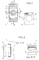
- a base 1 for a relay has a rectangular prismatic main body 2 located on its front face which incorporates a cylindrical boss 5 corresponding to the projection of the supporting base for a relay, bounded by the two side walls of the main body 2 and the protective wall for the two opposing external connection wires.
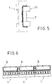
- the intermediate module 6 has a rectangular body with a central aperture 7 for receiving the boss 5.
- the base plate itself has the two rows of openings 4 required for connection of the terminal pins of the module 8, and two holes 3, intermediate between the two rows for location of supporting screws.
- This module 8 has two large opposing volumes tangential to the aperture 7, longitudinal on the outside and circular on the inside, and another two small volumes at right angles thereto with their tangents to the aperture 7, and therefore also perpendicular thereto. This more than doubles the available space and provides sufficient space for passing connections from one large volume to the other.
Landscapes
- Physics & Mathematics (AREA)
- Electromagnetism (AREA)
- Details Of Connecting Devices For Male And Female Coupling (AREA)
- Connecting Device With Holders (AREA)
- Coupling Device And Connection With Printed Circuit (AREA)
- Two-Way Televisions, Distribution Of Moving Picture Or The Like (AREA)
Applications Claiming Priority (2)
| Application Number | Priority Date | Filing Date | Title |
|---|---|---|---|
| ES9302280A ES2080660B1 (es) | 1993-11-02 | 1993-11-02 | Zocalo para rele que intercala un modulo electronico. |
| ES9302280 | 1993-11-02 |
Publications (2)
| Publication Number | Publication Date |
|---|---|
| EP0651414A2 true EP0651414A2 (fr) | 1995-05-03 |
| EP0651414A3 EP0651414A3 (fr) | 1995-12-13 |
Family
ID=8283482
Family Applications (1)
| Application Number | Title | Priority Date | Filing Date |
|---|---|---|---|
| EP94500170A Withdrawn EP0651414A3 (fr) | 1993-11-02 | 1994-10-28 | Socle pour un relais. |
Country Status (3)
| Country | Link |
|---|---|
| EP (1) | EP0651414A3 (fr) |
| ES (1) | ES2080660B1 (fr) |
| GB (1) | GB2286085B (fr) |
Cited By (2)
| Publication number | Priority date | Publication date | Assignee | Title |
|---|---|---|---|---|
| CN101246792B (zh) * | 2007-06-12 | 2010-05-19 | 上海继电器有限公司 | 埋入式继电器板前接线座 |
| EP2597661A1 (fr) | 2011-11-22 | 2013-05-29 | Marcel P. Hofsaess | Commutateur dépendant de la température |
Family Cites Families (11)
| Publication number | Priority date | Publication date | Assignee | Title |
|---|---|---|---|---|
| DE8216204U1 (de) * | 1982-06-04 | 1982-09-23 | Karl Lumberg GmbH & Co, 5885 Schalksmühle | Relaisfassung |
| ATE76247T1 (de) * | 1987-03-14 | 1992-05-15 | Staiger Steuerungstech | Dichtung. |
| US4773880A (en) * | 1987-04-28 | 1988-09-27 | Christopher Sutton | Circuit module for multi-pin connector |
| US4908597A (en) * | 1987-04-28 | 1990-03-13 | Christopher Sutton | Circuit module for multi-pin connector |
| FR2619973B1 (fr) * | 1987-08-26 | 1990-01-05 | France Etat | Dispositif de filtre echantillonne a capacites commutees |
| IT1220838B (it) * | 1988-02-10 | 1990-06-21 | Eaton Controls Spa | Dispositivo programmatore modulare con interconnessione integrata per l'organizzazione e il trasferimento dei contatti in uscita |
| US4846696A (en) * | 1988-06-15 | 1989-07-11 | M/A-Com Omni Spectra, Inc. | Microwave stripline connector |
| CH677554A5 (fr) * | 1989-04-27 | 1991-05-31 | Bircher Ag | |
| US5181859A (en) * | 1991-04-29 | 1993-01-26 | Trw Inc. | Electrical connector circuit wafer |
| US5112253A (en) * | 1991-08-15 | 1992-05-12 | Amphenol Corporation | Arrangement for removably mounting a transient suppression or electrical filter device in an electrical connector |
| DE9110962U1 (de) * | 1991-09-04 | 1991-10-31 | Comat AG, Worb | Stecksockel |
-
1993
- 1993-11-02 ES ES9302280A patent/ES2080660B1/es not_active Expired - Fee Related
-
1994
- 1994-02-07 GB GB9402276A patent/GB2286085B/en not_active Expired - Fee Related
- 1994-10-28 EP EP94500170A patent/EP0651414A3/fr not_active Withdrawn
Cited By (2)
| Publication number | Priority date | Publication date | Assignee | Title |
|---|---|---|---|---|
| CN101246792B (zh) * | 2007-06-12 | 2010-05-19 | 上海继电器有限公司 | 埋入式继电器板前接线座 |
| EP2597661A1 (fr) | 2011-11-22 | 2013-05-29 | Marcel P. Hofsaess | Commutateur dépendant de la température |
Also Published As
| Publication number | Publication date |
|---|---|
| ES2080660R (fr) | 1996-12-01 |
| GB9402276D0 (en) | 1994-03-30 |
| ES2080660B1 (es) | 1997-07-01 |
| EP0651414A3 (fr) | 1995-12-13 |
| ES2080660A2 (es) | 1996-02-01 |
| GB2286085B (en) | 1997-10-22 |
| GB2286085A (en) | 1995-08-02 |
Similar Documents
| Publication | Publication Date | Title |
|---|---|---|
| US5603355A (en) | Pilot type electromagnetic valve | |
| US4993956A (en) | Active electrical connector | |
| US4894633A (en) | Fuse Apparatus | |
| JPS587690A (ja) | 論理ボ−ドを保護するための密閉装置を有する陰極線管デイスプレイ端末装置 | |
| US6302745B1 (en) | Keying system for electrical connectors | |
| SU1658831A3 (ru) | Электрический контактор | |
| CA2411117A1 (fr) | Jack modulaire avec composants magnetiques | |
| WO1998026475A1 (fr) | Connecteur blinde | |
| ES2176020T3 (es) | Dispositivo de conexion para un conjunto de estructuras modulares paraporta-tarjetas electronicas y chasis equipado con tal dispositivo, para recibir tal conjunto. | |
| JP2000506316A (ja) | 電気機器のモジュール | |
| US5775950A (en) | Card-edge connector | |
| US5602723A (en) | Subrack device | |
| EP0651414A2 (fr) | Socle pour un relais | |
| US5606489A (en) | Ganged IROB in range out of building protector | |
| MY130144A (en) | Connector with press-fit terminal pins | |
| GB2161333A (en) | Electronics box for motor vehicles | |
| GB2283866A (en) | Through adaptor connector containing circuitry | |
| US5930118A (en) | Receiving device for components directly connected with a board | |
| JPS61101977A (ja) | 差込み要素 | |
| JPH02285698A (ja) | 電子機器用筺体 | |
| KR200447915Y1 (ko) | 퓨즈를 갖는 릴레이 | |
| CN218732041U (zh) | 一种汽车电源连接座 | |
| CN2330080Y (zh) | 具切换装置的电子卡插座连接器 | |
| KR910003962Y1 (ko) | 페이징 수신기등의 rom장착 장치 | |
| EP4521442A1 (fr) | Ensemble boîtier modulaire et connecteur électrique |
Legal Events
| Date | Code | Title | Description |
|---|---|---|---|
| PUAI | Public reference made under article 153(3) epc to a published international application that has entered the european phase |
Free format text: ORIGINAL CODE: 0009012 |
|
| AK | Designated contracting states |
Kind code of ref document: A2 Designated state(s): AT BE CH DE DK FR GR IE IT LI NL PT SE |
|
| 17P | Request for examination filed |
Effective date: 19950719 |
|
| PUAL | Search report despatched |
Free format text: ORIGINAL CODE: 0009013 |
|
| AK | Designated contracting states |
Kind code of ref document: A3 Designated state(s): AT BE CH DE DK FR GR IE IT LI NL PT SE |
|
| 17Q | First examination report despatched |
Effective date: 19970314 |
|
| GRAG | Despatch of communication of intention to grant |
Free format text: ORIGINAL CODE: EPIDOS AGRA |
|
| GRAG | Despatch of communication of intention to grant |
Free format text: ORIGINAL CODE: EPIDOS AGRA |
|
| GRAH | Despatch of communication of intention to grant a patent |
Free format text: ORIGINAL CODE: EPIDOS IGRA |
|
| STAA | Information on the status of an ep patent application or granted ep patent |
Free format text: STATUS: THE APPLICATION HAS BEEN WITHDRAWN |
|
| 18W | Application withdrawn |
Withdrawal date: 19980115 |