EP0651466A2 - Elektrische Flächen- und Randverbinder - Google Patents
Elektrische Flächen- und Randverbinder Download PDFInfo
- Publication number
- EP0651466A2 EP0651466A2 EP94117000A EP94117000A EP0651466A2 EP 0651466 A2 EP0651466 A2 EP 0651466A2 EP 94117000 A EP94117000 A EP 94117000A EP 94117000 A EP94117000 A EP 94117000A EP 0651466 A2 EP0651466 A2 EP 0651466A2
- Authority
- EP
- European Patent Office
- Prior art keywords
- contacts
- housing
- connector
- receiving areas
- contact
- Prior art date
- Legal status (The legal status is an assumption and is not a legal conclusion. Google has not performed a legal analysis and makes no representation as to the accuracy of the status listed.)
- Withdrawn
Links
Images

Classifications
-
- H—ELECTRICITY
- H01—ELECTRIC ELEMENTS
- H01R—ELECTRICALLY-CONDUCTIVE CONNECTIONS; STRUCTURAL ASSOCIATIONS OF A PLURALITY OF MUTUALLY-INSULATED ELECTRICAL CONNECTING ELEMENTS; COUPLING DEVICES; CURRENT COLLECTORS
- H01R13/00—Details of coupling devices of the kinds covered by groups H01R12/70 or H01R24/00 - H01R33/00
- H01R13/02—Contact members
- H01R13/22—Contacts for co-operating by abutting
- H01R13/24—Contacts for co-operating by abutting resilient; resiliently-mounted
- H01R13/2435—Contacts for co-operating by abutting resilient; resiliently-mounted with opposite contact points, e.g. C beam
-
- H—ELECTRICITY
- H01—ELECTRIC ELEMENTS
- H01R—ELECTRICALLY-CONDUCTIVE CONNECTIONS; STRUCTURAL ASSOCIATIONS OF A PLURALITY OF MUTUALLY-INSULATED ELECTRICAL CONNECTING ELEMENTS; COUPLING DEVICES; CURRENT COLLECTORS
- H01R12/00—Structural associations of a plurality of mutually-insulated electrical connecting elements, specially adapted for printed circuits, e.g. printed circuit boards [PCB], flat or ribbon cables, or like generally planar structures, e.g. terminal strips, terminal blocks; Coupling devices specially adapted for printed circuits, flat or ribbon cables, or like generally planar structures; Terminals specially adapted for contact with, or insertion into, printed circuits, flat or ribbon cables, or like generally planar structures
- H01R12/70—Coupling devices
- H01R12/71—Coupling devices for rigid printing circuits or like structures
- H01R12/712—Coupling devices for rigid printing circuits or like structures co-operating with the surface of the printed circuit or with a coupling device exclusively provided on the surface of the printed circuit
- H01R12/714—Coupling devices for rigid printing circuits or like structures co-operating with the surface of the printed circuit or with a coupling device exclusively provided on the surface of the printed circuit with contacts abutting directly the printed circuit; Button contacts therefore provided on the printed circuit
Definitions
- the present invention relates to electrical connectors and, more particularly, to area array and edge array electrical connectors.
- U.S. Patent 4,961,709 discloses one such connector with coiled column shaped contacts.
- U.S. Patent 4,906,194 discloses a serpentine contact used in an edge array electrical connector.
- U.S. Patents 5,184,962; 4,969,826; 4,927,369; 5,092,783; 5,061,192; and 5,069,627 disclose other types of contacts and connectors. Even in view of the above mentioned contacts and connectors, there exists a need for a connector for connecting parallel electrical components that has very small contacts, which is dependable and relatively easy to manufacture, and can be manufactured at a relatively low expense.
- an electrical connector comprising a housing and a plurality of spring contacts.
- the housing has a plurality of contact receiving areas.
- the spring contacts are one piece serpentine shaped contacts connected to the housing in the receiving areas.
- the contacts have two reversely orientated spring arms connected by a center section. Ends of the spring arms of each contact extend out of opposite open ends of one of the receiving areas and, the center section has mounting wings that connect the contacts to the housing.
- an electrical connector comprising a housing and a plurality of electrical contacts.
- the housing has a plurality of contact receiving areas extending through the housing from a first side to a second side.
- the receiving areas have a uniform general cross-like shape.
- the electrical contacts are connected to the housing in the receiving areas.
- the contacts are comprised of a sheet of flat metal that is cut and stamped into dual spring arms with lateral mounting wings. The dual spring arms extend out of the receiving areas at the first and second sides and, the lateral mounting wings fixedly mount each contact to the housing.
- FIG. 1 there is shown a partial cross sectional view of an electrical connector 10 incorporating features of the present invention for electrically connecting two parallel printed circuit boards 12, 14 to each other.
- the present invention will be described with reference to the single embodiment shown in the drawings, it should be understood that the present invention can be embodied in various different types and forms of alternate embodiments. In addition, any suitable size, shape and type of elements or materials could be used.
- the electrical connector 10 can be used to electrical connect other types of electrical or electronic components to each other. Therefore, as used herein, the term printed circuit board should be interpreted to mean any type of electrical or electronic component.
- the connector 10 generally comprises a housing 16 and a plurality of electrical contacts 18 (only one of which is shown connected to the housing 16 in Fig. 1 for the sake of clarity).
- the housing 16 is comprised of a dielectric material, such as a molded polymer or plastic material.
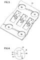
- the housing 16 has a plurality of contact receiving areas 20 (only one of which is shown in Figs. 1 and 4 for the sake of clarity).
- the receiving areas 20 extend through the housing 16 from a first side 22 to a second side 24 with a uniform general cross-like shape as seen best in Fig. 4.
- Each receiving area 20 is comprised of a center aperture 26 and two lateral apertures 28 extending from opposite sides of the center aperture 26 to form the general cross-like shape. In alternate embodiments, the lateral apertures could be angled relative to the center aperture 26 or each other.
- the important feature in the embodiment shown is that the two apertures 28 extend laterally from the center aperture 26.
- the contact receiving areas 20 can be arranged in any suitable pattern or array.
- each contact 18 is a one-piece metal member that has a general serpentine side profile as shown best in Fig. 1.
- each contact 18 has a pair of reversely oriented curved spring arms 30, 31 connected to each other by a center section 32.
- the arms 30, 31 are substantially the same, but merely reversely oriented.
- the center section 32 includes two laterally extending mounting wings 34.
- the heigt H of the contacts is about 1.27 mm (0.05 inch).
- the width W of the spring arms 30, 31 is about 0.25 mm (0.01 inch).
- the width W' between the opposite ends of the two mounting wings 34, 34 is about 0.66 mm (0.026 inch).
- the thickness of the contact is about 0.076 mm (0.003 inch). In alternate embodiments, other sizes or dimensions could be provided.
- Each of the contacts 18 is mounted to the housing 16 with the two mounting wings 34 located in the two lateral apertures 28 and the rest of the contact being located in the center aperture 26 and extending out of the opposite sides 22, 24 as seen in Fig. 1.
- the ends 36, 37 of the spring arms 30, 31 extend out of the center aperture 26 as shown.
- the ends 36, 37 are designed to electrically contact pads 38, 39 on the printed circuit boards 12, 14, respectively.
- the ends 36, 37 are contacted by the contact pads 38, 39 and deflected inward. This forms an electrical spring contact connection between the two pads 38, 39 such that the boards 12, 14 are electrically connected to each other.
- the mounting wings 34 are located in the lateral apertures 28.
- the mounting wings 34 form an interference fit inside the lateral apertures 28 with the housing 16. This fixedly mounts the center section 32, and thus the entire contact 18, to the housing.
- the wings 34 could have barbs or the like at their ends to assist in making the interference fit.
- a flat sheet of metal 40 that is used to form the contacts 18.
- the sheet 40 has indexing holes 42 to allow the sheet 40 to be fed through a cutting and stamping machine (not shown).
- the machine (not shown) cuts the sheet 40 to form flat contact blanks that are then stamped or otherwise deformed into the series of contacts 18 that can be easily removed from the sheet 40 and connected to the housing 16 of the connector 10.
- similar contact forming techniques are known in the art, the process has been described to emphasize that the contacts 18 are comprised of a flat sheet of metal that has been cut and stamped to form the contacts 18. This is important because contacts made from flat sheet stock material are one of the easiest types of contacts to manufacture and also one of the least expensive types of contacts to manufacture.
- the shape of the spring arms 30, 31 also provides adequate deflection and contact force against the pads 38, 39 for a good electrical connection.
- the connector 10 has a small size, can be manufactured at a reasonable cost, and has a good physical mounting of the contacts to the housing.
Landscapes
- Coupling Device And Connection With Printed Circuit (AREA)
Applications Claiming Priority (2)
| Application Number | Priority Date | Filing Date | Title |
|---|---|---|---|
| US143433 | 1993-10-27 | ||
| US08/143,433 US5395252A (en) | 1993-10-27 | 1993-10-27 | Area and edge array electrical connectors |
Publications (2)
| Publication Number | Publication Date |
|---|---|
| EP0651466A2 true EP0651466A2 (de) | 1995-05-03 |
| EP0651466A3 EP0651466A3 (de) | 1995-09-20 |
Family
ID=22504058
Family Applications (1)
| Application Number | Title | Priority Date | Filing Date |
|---|---|---|---|
| EP94117000A Withdrawn EP0651466A3 (de) | 1993-10-27 | 1994-10-27 | Elektrische Flächen- und Randverbinder. |
Country Status (3)
| Country | Link |
|---|---|
| US (1) | US5395252A (de) |
| EP (1) | EP0651466A3 (de) |
| JP (1) | JPH07254462A (de) |
Cited By (1)
| Publication number | Priority date | Publication date | Assignee | Title |
|---|---|---|---|---|
| US5893761A (en) * | 1996-02-12 | 1999-04-13 | Siemens Aktiengesellschaft | Printed circuit board connector |
Families Citing this family (67)
| Publication number | Priority date | Publication date | Assignee | Title |
|---|---|---|---|---|
| FR2703839B1 (fr) * | 1993-04-09 | 1995-07-07 | Framatome Connectors France | Connecteur intermédiaire entre carte de circuit imprimé et substrat à circuits électroniques. |
| TW381328B (en) * | 1994-03-07 | 2000-02-01 | Ibm | Dual substrate package assembly for being electrically coupled to a conducting member |
| US5653612A (en) * | 1995-08-15 | 1997-08-05 | Framatome Connectors Usa Inc. | Electrical contact assembly with stabilizing contact mount |
| US5975959A (en) * | 1996-12-17 | 1999-11-02 | The Whitaker Corporation | Smart card connector module |
| US6204065B1 (en) * | 1997-03-27 | 2001-03-20 | Ngk Insulators, Ltd. | Conduction assist member and manufacturing method of the same |
| JP3406180B2 (ja) * | 1997-04-21 | 2003-05-12 | ヒロセ電機株式会社 | 中間電気コネクタ |
| US6409521B1 (en) | 1997-05-06 | 2002-06-25 | Gryphics, Inc. | Multi-mode compliant connector and replaceable chip module utilizing the same |
| AU7281698A (en) | 1997-05-06 | 1998-11-27 | Gryphics, Inc. | Multi-mode compliant connector and replaceable chip module utilizing the same |
| US5938451A (en) * | 1997-05-06 | 1999-08-17 | Gryphics, Inc. | Electrical connector with multiple modes of compliance |
| US5913687A (en) | 1997-05-06 | 1999-06-22 | Gryphics, Inc. | Replacement chip module |
| US6045367A (en) * | 1997-09-24 | 2000-04-04 | Teledyne Industries, Inc. | Multi-pin connector |
| US6290507B1 (en) | 1997-10-30 | 2001-09-18 | Intercon Systems, Inc. | Interposer assembly |
| US6217342B1 (en) | 1997-10-30 | 2001-04-17 | Intercon Systems, Inc. | Interposer assembly |
| US6315576B1 (en) | 1997-10-30 | 2001-11-13 | Intercon Systems, Inc. | Interposer assembly |
| US6267603B1 (en) * | 1998-04-01 | 2001-07-31 | Molex Incorporated | Burn-in test socket |
| JP3982050B2 (ja) * | 1998-04-06 | 2007-09-26 | 株式会社日本自動車部品総合研究所 | 回路基板へのコネクタ接続構造 |
| US5984693A (en) * | 1998-12-17 | 1999-11-16 | Hon Hai Precision Ind. Co., Ltd. | Contact of an LGA socket |
| JP2003536203A (ja) | 1999-02-02 | 2003-12-02 | グリフィクス インコーポレーティッド | プリント回路基板及び電気装置のための低挿入力又はゼロ挿入力のコネクタ |
| US6217341B1 (en) * | 1999-04-01 | 2001-04-17 | Wells-Cti, Inc. | Integrated circuit test socket having torsion wire contacts |
| JP3035544B1 (ja) * | 1999-05-10 | 2000-04-24 | エスエムケイ株式会社 | コネクタタ―ミナル |
| US6830460B1 (en) * | 1999-08-02 | 2004-12-14 | Gryphics, Inc. | Controlled compliance fine pitch interconnect |
| US6186797B1 (en) * | 1999-08-12 | 2001-02-13 | Hon Hai Precision Ind. Co., Ltd. | Land grid array connector |
| US6957963B2 (en) * | 2000-01-20 | 2005-10-25 | Gryphics, Inc. | Compliant interconnect assembly |
| AU2001232772A1 (en) * | 2000-01-20 | 2001-07-31 | Gryphics, Inc. | Flexible compliant interconnect assembly |
| TW433591U (en) * | 2000-02-02 | 2001-05-01 | Hon Hai Prec Ind Co Ltd | Electrical connector |
| US6328573B1 (en) * | 2000-02-29 | 2001-12-11 | Hirose Electric Co., Ltd. | Intermediate electrical connector |
| US6604950B2 (en) * | 2001-04-26 | 2003-08-12 | Teledyne Technologies Incorporated | Low pitch, high density connector |
| US6585527B2 (en) | 2001-05-31 | 2003-07-01 | Samtec, Inc. | Compliant connector for land grid array |
| US6586684B2 (en) * | 2001-06-29 | 2003-07-01 | Intel Corporation | Circuit housing clamp and method of manufacture therefor |
| US6730134B2 (en) * | 2001-07-02 | 2004-05-04 | Intercon Systems, Inc. | Interposer assembly |
| US6488513B1 (en) | 2001-12-13 | 2002-12-03 | Intercon Systems, Inc. | Interposer assembly for soldered electrical connections |
| SG104969A1 (en) * | 2002-05-24 | 2004-07-30 | Fci Asia Technology Pte Ltd | An electrical connector |
| TW570346U (en) * | 2003-03-12 | 2004-01-01 | Hon Hai Prec Ind Co Ltd | Contact for electrical connector |
| US6906404B2 (en) * | 2003-05-16 | 2005-06-14 | Ballard Power Systems Corporation | Power module with voltage overshoot limiting |
| US7505294B2 (en) * | 2003-05-16 | 2009-03-17 | Continental Automotive Systems Us, Inc. | Tri-level inverter |
| US6987670B2 (en) * | 2003-05-16 | 2006-01-17 | Ballard Power Systems Corporation | Dual power module power system architecture |
| US7443692B2 (en) * | 2003-05-16 | 2008-10-28 | Continental Automotive Systems Us, Inc. | Power converter architecture employing at least one capacitor across a DC bus |
| TW573838U (en) * | 2003-06-05 | 2004-01-21 | Molex Taiwan Ltd | Conductive terminal and electrical connector using the same |
| US7455556B2 (en) * | 2003-06-11 | 2008-11-25 | Cinch Connectors, Inc. | Electrical contact |
| US6921270B2 (en) * | 2003-06-11 | 2005-07-26 | Cinch Connectors, Inc. | Electrical connector |
| US7625216B2 (en) * | 2003-06-11 | 2009-12-01 | Cinch Connectors, Inc. | Electrical connector |
| TWM250411U (en) * | 2003-07-04 | 2004-11-11 | Hon Hai Prec Ind Co Ltd | Land grid array socket |
| WO2005008838A1 (en) | 2003-07-07 | 2005-01-27 | Gryphics, Inc. | Normally closed zero insertion force connector |
| JP4602649B2 (ja) * | 2003-07-23 | 2010-12-22 | ティーエヌジー コーポレーション リミテッド | 電子部品用ソケット |
| US6945788B2 (en) * | 2003-07-31 | 2005-09-20 | Tyco Electronics Corporation | Metal contact LGA socket |
| US20050128706A1 (en) * | 2003-12-16 | 2005-06-16 | Ballard Power Systems Corporation | Power module with heat exchange |
| CN100373995C (zh) * | 2004-01-05 | 2008-03-05 | 番禺得意精密电子工业有限公司 | 导电体植设方法及使用这种方法的电路板与芯片 |
| TWM256608U (en) * | 2004-02-06 | 2005-02-01 | Hon Hai Prec Ind Co Ltd | Socket connector |
| US6971885B2 (en) * | 2004-02-18 | 2005-12-06 | Teledyne Technologies Incorporated | Interconnect device with opposingly oriented contacts |
| US7289329B2 (en) * | 2004-06-04 | 2007-10-30 | Siemens Vdo Automotive Corporation | Integration of planar transformer and/or planar inductor with power switches in power converter |
| US7295448B2 (en) * | 2004-06-04 | 2007-11-13 | Siemens Vdo Automotive Corporation | Interleaved power converter |
| US7180763B2 (en) * | 2004-09-21 | 2007-02-20 | Ballard Power Systems Corporation | Power converter |
| JP2008517582A (ja) * | 2004-10-20 | 2008-05-22 | シーメンス ヴィディーオー オートモーティヴ コーポレイション | 電力システム、方法および装置 |
| CN1848534B (zh) * | 2005-04-13 | 2010-06-02 | 上海莫仕连接器有限公司 | 电源连接器的导电端子及其制造方法 |
| EP1897214A2 (de) * | 2005-06-30 | 2008-03-12 | Siemens VDO Automotive Corporation | Für einen elektrischen antrieb geeignete(s) steuerverfahren, -vorrichtung und -steuerartikel |
| US7599520B2 (en) | 2005-11-18 | 2009-10-06 | Accenture Global Services Gmbh | Detection of multiple targets on a plane of interest |
| DE102006020955B4 (de) * | 2006-05-05 | 2010-12-02 | Lumberg Connect Gmbh | Andruckkontakt und Andruckverbinder |
| WO2007138952A1 (ja) * | 2006-05-30 | 2007-12-06 | Fujikura Ltd. | ソケット用コンタクト端子及び半導体装置 |
| US8419473B1 (en) * | 2012-01-05 | 2013-04-16 | Cheng Uei Precision Industry Co., Ltd. | Electrical connector |
| US8672688B2 (en) * | 2012-01-17 | 2014-03-18 | International Business Machines Corporation | Land grid array interposer with compressible conductors |
| JP2013175473A (ja) * | 2013-05-07 | 2013-09-05 | Japan Aviation Electronics Industry Ltd | コネクタ |
| CN104319519A (zh) * | 2014-08-29 | 2015-01-28 | 中航光电科技股份有限公司 | 弹性接触簧及使用该接触簧的转接器 |
| JP5930337B2 (ja) * | 2014-09-02 | 2016-06-08 | 日本航空電子工業株式会社 | コネクタ |
| DE102015212163B4 (de) | 2015-06-30 | 2024-05-29 | Robert Bosch Gmbh | Kontaktfeder für eine Anzeigevorrichtung, Anzeigevorrichtung und Verfahren zum Herstellen einer Anzeigevorrichtung |
| JP6438639B2 (ja) * | 2016-05-22 | 2018-12-19 | 大和電器株式会社 | 配線器具 |
| GB201615140D0 (en) * | 2016-09-06 | 2016-10-19 | Quanta Dialysis Tech Ltd | Liquid conductivity measurement pin |
| US12051865B2 (en) * | 2021-12-28 | 2024-07-30 | Te Connectivity Solutions Gmbh | Socket connector |
Family Cites Families (13)
| Publication number | Priority date | Publication date | Assignee | Title |
|---|---|---|---|---|
| DE7910787U1 (de) * | 1979-04-12 | 1980-10-23 | Karl Lumberg Gmbh & Co, 5885 Schalksmuehle | Kontaktleiste |
| US4961709A (en) * | 1989-02-13 | 1990-10-09 | Burndy Corporation | Vertical action contact spring |
| US4927369A (en) * | 1989-02-22 | 1990-05-22 | Amp Incorporated | Electrical connector for high density usage |
| US4906194A (en) * | 1989-04-13 | 1990-03-06 | Amp Incorporated | High density connector for an IC chip carrier |
| US4975062A (en) * | 1989-05-19 | 1990-12-04 | Motorola, Inc. | Hermaphroditic connector |
| US4969826A (en) * | 1989-12-06 | 1990-11-13 | Amp Incorporated | High density connector for an IC chip carrier |
| US5069627A (en) * | 1990-06-19 | 1991-12-03 | Amp Incorporated | Adjustable stacking connector for electrically connecting circuit boards |
| US5092783A (en) * | 1991-05-16 | 1992-03-03 | Motorola, Inc. | RF interconnect |
| US5139427A (en) * | 1991-09-23 | 1992-08-18 | Amp Incorporated | Planar array connector and flexible contact therefor |
| GB9122052D0 (en) * | 1991-10-17 | 1991-11-27 | Amp Holland | Printed circuit board electrical connector |
| US5184962A (en) * | 1991-12-05 | 1993-02-09 | Burndy Corporation | Electrical spring contact |
| US5259769A (en) * | 1992-09-29 | 1993-11-09 | Molex Incorporated | Electrical connector with preloaded spring-like terminal with improved wiping action |
| JPH06325810A (ja) * | 1993-03-08 | 1994-11-25 | Whitaker Corp:The | コンタクトモジュール及びそれを使用するピングリッドアレイ |
-
1993
- 1993-10-27 US US08/143,433 patent/US5395252A/en not_active Expired - Fee Related
-
1994
- 1994-10-27 JP JP6264226A patent/JPH07254462A/ja not_active Withdrawn
- 1994-10-27 EP EP94117000A patent/EP0651466A3/de not_active Withdrawn
Cited By (1)
| Publication number | Priority date | Publication date | Assignee | Title |
|---|---|---|---|---|
| US5893761A (en) * | 1996-02-12 | 1999-04-13 | Siemens Aktiengesellschaft | Printed circuit board connector |
Also Published As
| Publication number | Publication date |
|---|---|
| JPH07254462A (ja) | 1995-10-03 |
| US5395252A (en) | 1995-03-07 |
| EP0651466A3 (de) | 1995-09-20 |
Similar Documents
| Publication | Publication Date | Title |
|---|---|---|
| US5395252A (en) | Area and edge array electrical connectors | |
| US5800186A (en) | Printed circuit board assembly | |
| US5468154A (en) | Multi-piece housing card edge connector with mounting arms | |
| US6206735B1 (en) | Press fit print circuit board connector | |
| EP0651470B1 (de) | Leiterplattenrandverbinder mit Kontakten von verminderten Teilung | |
| US5906496A (en) | Miniature card edge clip | |
| US6561850B2 (en) | High speed card edge connectors | |
| EP0838101B1 (de) | Elektrische verbinder | |
| EP0724313A2 (de) | Auf eine Leiterplatte montierter elektrischer Steckverbinder | |
| US6039590A (en) | Electrical connector with relatively movable two-part housing | |
| WO1998028818A9 (en) | Miniature card edge clip | |
| EP0798816B1 (de) | Anordnung zum Fixieren von einem elektrischen Verbinder an einer Leiterplatte | |
| US7112072B2 (en) | Ground bus for an electrical connector | |
| US5184962A (en) | Electrical spring contact | |
| US4538878A (en) | Solderless circuit board connector | |
| JPH0950842A (ja) | プレスインコンタクト及びその製造方法 | |
| EP0542068B1 (de) | Elektrische Kontaktbuchse | |
| US6692273B1 (en) | Straddle mount connector | |
| US6159049A (en) | Electrical contact and bandolier assembly | |
| US5518426A (en) | Electrical connector and method of assembling an electrical connector with rows of interspaced contacts | |
| US5324215A (en) | Dual beam electrical contact | |
| GB2225492A (en) | Electrical connector for PCB | |
| US20040166707A1 (en) | Electrical connector having a holddown for ground connection | |
| US6132247A (en) | Metallic one-piece hold-down and an electrical connector with the hold-down | |
| JPH11339906A (ja) | 基板取付型コネクタ |
Legal Events
| Date | Code | Title | Description |
|---|---|---|---|
| PUAI | Public reference made under article 153(3) epc to a published international application that has entered the european phase |
Free format text: ORIGINAL CODE: 0009012 |
|
| AK | Designated contracting states |
Kind code of ref document: A2 Designated state(s): BE DE ES FR GB IT NL SE |
|
| PUAL | Search report despatched |
Free format text: ORIGINAL CODE: 0009013 |
|
| AK | Designated contracting states |
Kind code of ref document: A3 Designated state(s): BE DE ES FR GB IT NL SE |
|
| STAA | Information on the status of an ep patent application or granted ep patent |
Free format text: STATUS: THE APPLICATION IS DEEMED TO BE WITHDRAWN |
|
| 18D | Application deemed to be withdrawn |
Effective date: 19960321 |