EP0651488A1 - Dispositif de protection électrique - Google Patents
Dispositif de protection électrique Download PDFInfo
- Publication number
- EP0651488A1 EP0651488A1 EP94307344A EP94307344A EP0651488A1 EP 0651488 A1 EP0651488 A1 EP 0651488A1 EP 94307344 A EP94307344 A EP 94307344A EP 94307344 A EP94307344 A EP 94307344A EP 0651488 A1 EP0651488 A1 EP 0651488A1
- Authority
- EP
- European Patent Office
- Prior art keywords
- detecting
- protection device
- latch
- output signal
- fault
- Prior art date
- Legal status (The legal status is an assumption and is not a legal conclusion. Google has not performed a legal analysis and makes no representation as to the accuracy of the status listed.)
- Withdrawn
Links
- 238000001514 detection method Methods 0.000 claims abstract description 3
- 239000004065 semiconductor Substances 0.000 claims description 3
- 238000010586 diagram Methods 0.000 description 1
Images
Classifications
-
- H—ELECTRICITY
- H01—ELECTRIC ELEMENTS
- H01H—ELECTRIC SWITCHES; RELAYS; SELECTORS; EMERGENCY PROTECTIVE DEVICES
- H01H83/00—Protective switches, e.g. circuit-breaking switches, or protective relays operated by abnormal electrical conditions otherwise than solely by excess current
- H01H83/20—Protective switches, e.g. circuit-breaking switches, or protective relays operated by abnormal electrical conditions otherwise than solely by excess current operated by excess current as well as by some other abnormal electrical condition
-
- H—ELECTRICITY
- H02—GENERATION; CONVERSION OR DISTRIBUTION OF ELECTRIC POWER
- H02H—EMERGENCY PROTECTIVE CIRCUIT ARRANGEMENTS
- H02H3/00—Emergency protective circuit arrangements for automatic disconnection directly responsive to an undesired change from normal electric working condition with or without subsequent reconnection ; integrated protection
- H02H3/08—Emergency protective circuit arrangements for automatic disconnection directly responsive to an undesired change from normal electric working condition with or without subsequent reconnection ; integrated protection responsive to excess current
- H02H3/10—Emergency protective circuit arrangements for automatic disconnection directly responsive to an undesired change from normal electric working condition with or without subsequent reconnection ; integrated protection responsive to excess current additionally responsive to some other abnormal electrical conditions
- H02H3/105—Emergency protective circuit arrangements for automatic disconnection directly responsive to an undesired change from normal electric working condition with or without subsequent reconnection ; integrated protection responsive to excess current additionally responsive to some other abnormal electrical conditions responsive to excess current and fault current to earth
Definitions
- THIS INVENTION relates to a protection device. More particularly, the invention relates to an electrical protection device.
- an electrical protection device which includes a detecting means for detecting a fault and for generating an output signal upon detection of such a fault; and a latch device, responsive to the output signal, for disconnecting an electrical supply from a load upon receipt of the output signal.
- the detecting means and the latch device are arranged in a common housing. Then, the latch device is operable remote from the housing. In addition, the latch device may be operable at the housing.
- the detecting means may comprise a plurality of detecting units for detecting various types of faults, the latch device being responsive to an output signal from any one of the detecting units.
- the detecting means may comprise an over-current detecting unit, a short circuit detecting unit and an earth leakage detecting unit.
- the latch device may be a semiconductor device or, instead, the latch device may be an electromechanical device.
- the need for local operation is obviated as the device can be operated remotely by means of a suitable switching arrangement. Further, the need for additional electrical apparatus to facilitate remote operation is obviated.
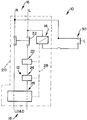
- an electrical protection device in accordance with the invention, is illustrated and is designated generally by the reference numeral 10.
- the device 10 includes a detecting means 12 for detecting a fault and for generating an output signal when such fault is detected.
- a latch device, or latch, 14 is responsive to said output signal and disconnects an electrical supply 16 from a load 18 upon receipt of said output signal.
- the detecting means 12 and the latch 14 are arranged in a common housing 20.
- the device 10 is intended particularly for use in circuit breaker-type applications to replace a circuit breaker.
- the detecting means 12 comprises a plurality of detecting units 22, 24 and 26 for detecting various types of faults.
- the detecting unit 22 is operable to detect an overcurrent fault
- the detecting unit 24 is operable to detect a short circuit fault
- the detecting unit 26 is operable to detect an earth leakage fault.
- the detecting units 22, 24 and 26 are connected by a line 28 to the latch 14.
- the latch 14 is responsive to a signal output from any one of the detecting units 22, 24, 26.
- a remote operating element in the form of a switch 30 is connected to the latch 14 for facilitating remote operation of said latch 14.
- the latch 14 controls a set of contacts 32 for making or breaking an electrical connection between the supply 16 and the load 18.
- the latch 14 can either be in the form of a semiconductor device or it may be an electro-mechanical device such as a latching relay.
- the contacts 32 are closed and the load 18 is connected to the supply 16.
- a signal is sent along line 28 to the latch 14 causing it to change state. This results in the contacts 32 disconnecting the load 18 from the supply 16 in a circuit breaker-like manner.
- either the contact 32 can be closed manually or the latch 14 can be operated remotely by means of the switch 30.
- a protection device 10 which performs a circuit breaker-like operation but which has the added advantage that it can be operated remotely.
- it is a problem with a conventional circuit breaker that it must be operated locally by means of a handle fitted on an accessible area of a housing of the circuit breaker. If remote operation is required, an additional electrical apparatus must be used. This problem is, to a large extent, overcome by means of the device 10.
Landscapes
- Breakers (AREA)
Applications Claiming Priority (2)
| Application Number | Priority Date | Filing Date | Title |
|---|---|---|---|
| ZA938009 | 1993-10-27 | ||
| ZA938009 | 1993-10-27 |
Publications (1)
| Publication Number | Publication Date |
|---|---|
| EP0651488A1 true EP0651488A1 (fr) | 1995-05-03 |
Family
ID=25583359
Family Applications (1)
| Application Number | Title | Priority Date | Filing Date |
|---|---|---|---|
| EP94307344A Withdrawn EP0651488A1 (fr) | 1993-10-27 | 1994-10-06 | Dispositif de protection électrique |
Country Status (2)
| Country | Link |
|---|---|
| EP (1) | EP0651488A1 (fr) |
| ZA (1) | ZA947576B (fr) |
Cited By (2)
| Publication number | Priority date | Publication date | Assignee | Title |
|---|---|---|---|---|
| US7378761B2 (en) | 2002-08-02 | 2008-05-27 | Protectelec Pty Ltd | Control circuit and a method for electrically connecting a load to a power source |
| EP2727126A1 (fr) * | 2011-11-02 | 2014-05-07 | Siemens Aktiengesellschaft | Unité de déclenchement destinée à déclencher un élément de déclenchement d'un appareil de commutation électrique et appareil de commutation électrique |
Citations (4)
| Publication number | Priority date | Publication date | Assignee | Title |
|---|---|---|---|---|
| GB1136836A (en) * | 1966-01-25 | 1968-12-18 | Uninorm Anstalt | Leakage current protection switch with excess current release |
| US4068283A (en) * | 1976-10-01 | 1978-01-10 | General Electric Company | Circuit breaker solid state trip unit incorporating trip indicating circuit |
| US4860157A (en) * | 1988-04-25 | 1989-08-22 | General Electric Company | Molded case circuit breaker actuator-accessory module |
| DE4202910A1 (de) * | 1992-02-01 | 1993-08-05 | Oppach Schaltelektronik | Funktionsbaustein fuer befehls- und meldegeraete |
-
1994
- 1994-09-28 ZA ZA947576A patent/ZA947576B/xx unknown
- 1994-10-06 EP EP94307344A patent/EP0651488A1/fr not_active Withdrawn
Patent Citations (4)
| Publication number | Priority date | Publication date | Assignee | Title |
|---|---|---|---|---|
| GB1136836A (en) * | 1966-01-25 | 1968-12-18 | Uninorm Anstalt | Leakage current protection switch with excess current release |
| US4068283A (en) * | 1976-10-01 | 1978-01-10 | General Electric Company | Circuit breaker solid state trip unit incorporating trip indicating circuit |
| US4860157A (en) * | 1988-04-25 | 1989-08-22 | General Electric Company | Molded case circuit breaker actuator-accessory module |
| DE4202910A1 (de) * | 1992-02-01 | 1993-08-05 | Oppach Schaltelektronik | Funktionsbaustein fuer befehls- und meldegeraete |
Cited By (2)
| Publication number | Priority date | Publication date | Assignee | Title |
|---|---|---|---|---|
| US7378761B2 (en) | 2002-08-02 | 2008-05-27 | Protectelec Pty Ltd | Control circuit and a method for electrically connecting a load to a power source |
| EP2727126A1 (fr) * | 2011-11-02 | 2014-05-07 | Siemens Aktiengesellschaft | Unité de déclenchement destinée à déclencher un élément de déclenchement d'un appareil de commutation électrique et appareil de commutation électrique |
Also Published As
| Publication number | Publication date |
|---|---|
| ZA947576B (en) | 1995-05-15 |
Similar Documents
| Publication | Publication Date | Title |
|---|---|---|
| US7233463B2 (en) | Method and apparatus for detecting electrical faults and isolating power source from the electrical faults | |
| US3787708A (en) | Monitor system for ground fault relay | |
| US12562559B2 (en) | Arc flash mitigation device | |
| US4156884A (en) | Ground fault protection system for industrial power circuits | |
| CA2340397C (fr) | Circuit de surveillance pour dispositif limitateur de courant | |
| JPH0654437A (ja) | 差電流保護開閉器 | |
| US6034447A (en) | Connector for consumer networks | |
| EP0651488A1 (fr) | Dispositif de protection électrique | |
| US6628485B1 (en) | Apparatus for limiting an electrical current | |
| GB2272119A (en) | Circuit breaker trip circuit supervision | |
| KR100256019B1 (ko) | 전선로의 비상보호장치 | |
| JP4562160B2 (ja) | 感震装置 | |
| EP0637866B1 (fr) | Un dispositif de contrôle et de protection pour un système électrique | |
| JPH10336880A (ja) | 過電圧検出回路 | |
| JPH03245730A (ja) | 分電盤装置 | |
| KR200189438Y1 (ko) | 간이형 3상4선식 결상보호 회로 및 장치(3-phase 4-line type open-phase protecting circuit and device) | |
| JP3360968B2 (ja) | 保護継電器 | |
| SU1591099A1 (ru) | Устройство для контроля исправности релейной зашиты | |
| JP3059053B2 (ja) | 母線保護継電装置の断路器接点情報監視装置 | |
| KR19990032399A (ko) | 차단기의 온(on)/오프(off) 회로 감시장치 | |
| KR930017259A (ko) | 전동기 보호용 계전기 | |
| GB2162003A (en) | Earth leakage circuit breakers | |
| ATE180113T1 (de) | Fehlerstromschutzschaltung in drehstromsystemen | |
| JPH05205606A (ja) | 回路遮断器の外部報知装置 | |
| JPH06342029A (ja) | 地絡検出装置 |
Legal Events
| Date | Code | Title | Description |
|---|---|---|---|
| PUAI | Public reference made under article 153(3) epc to a published international application that has entered the european phase |
Free format text: ORIGINAL CODE: 0009012 |
|
| AK | Designated contracting states |
Kind code of ref document: A1 Designated state(s): AT DE FR GB IT NL SE |
|
| 17P | Request for examination filed |
Effective date: 19950707 |
|
| R17P | Request for examination filed (corrected) |
Effective date: 19950707 |
|
| STAA | Information on the status of an ep patent application or granted ep patent |
Free format text: STATUS: THE APPLICATION HAS BEEN WITHDRAWN |
|
| 18W | Application withdrawn |
Withdrawal date: 19960325 |