EP0651496A1 - Elektrische Maschine - Google Patents
Elektrische Maschine Download PDFInfo
- Publication number
- EP0651496A1 EP0651496A1 EP94307832A EP94307832A EP0651496A1 EP 0651496 A1 EP0651496 A1 EP 0651496A1 EP 94307832 A EP94307832 A EP 94307832A EP 94307832 A EP94307832 A EP 94307832A EP 0651496 A1 EP0651496 A1 EP 0651496A1
- Authority
- EP
- European Patent Office
- Prior art keywords
- cage
- stack
- laminations
- metal alloys
- electric machine
- Prior art date
- Legal status (The legal status is an assumption and is not a legal conclusion. Google has not performed a legal analysis and makes no representation as to the accuracy of the status listed.)
- Withdrawn
Links
- 239000000463 material Substances 0.000 claims abstract description 30
- 238000003475 lamination Methods 0.000 claims abstract description 23
- 230000009974 thixotropic effect Effects 0.000 claims abstract description 15
- 229910000881 Cu alloy Inorganic materials 0.000 claims abstract description 9
- 238000004519 manufacturing process Methods 0.000 claims abstract description 9
- RYGMFSIKBFXOCR-UHFFFAOYSA-N Copper Chemical compound [Cu] RYGMFSIKBFXOCR-UHFFFAOYSA-N 0.000 claims description 12
- 239000004411 aluminium Substances 0.000 claims description 12
- XAGFODPZIPBFFR-UHFFFAOYSA-N aluminium Chemical compound [Al] XAGFODPZIPBFFR-UHFFFAOYSA-N 0.000 claims description 12
- 239000010949 copper Substances 0.000 claims description 12
- 238000000034 method Methods 0.000 claims description 11
- 229910052802 copper Inorganic materials 0.000 claims description 9
- 229910045601 alloy Inorganic materials 0.000 claims description 8
- 239000000956 alloy Substances 0.000 claims description 8
- 229910052782 aluminium Inorganic materials 0.000 claims description 8
- 229910001092 metal group alloy Inorganic materials 0.000 claims description 6
- 229910052755 nonmetal Inorganic materials 0.000 claims description 6
- 239000004020 conductor Substances 0.000 claims description 5
- 229910000838 Al alloy Inorganic materials 0.000 claims description 4
- QVGXLLKOCUKJST-UHFFFAOYSA-N atomic oxygen Chemical compound [O] QVGXLLKOCUKJST-UHFFFAOYSA-N 0.000 claims description 2
- BERDEBHAJNAUOM-UHFFFAOYSA-N copper(I) oxide Inorganic materials [Cu]O[Cu] BERDEBHAJNAUOM-UHFFFAOYSA-N 0.000 claims description 2
- KRFJLUBVMFXRPN-UHFFFAOYSA-N cuprous oxide Chemical compound [O-2].[Cu+].[Cu+] KRFJLUBVMFXRPN-UHFFFAOYSA-N 0.000 claims description 2
- 229940112669 cuprous oxide Drugs 0.000 claims description 2
- 238000002347 injection Methods 0.000 claims description 2
- 239000007924 injection Substances 0.000 claims description 2
- 229910052760 oxygen Inorganic materials 0.000 claims description 2
- 239000001301 oxygen Substances 0.000 claims description 2
- 239000006104 solid solution Substances 0.000 claims description 2
- 238000004512 die casting Methods 0.000 description 5
- 230000006698 induction Effects 0.000 description 3
- 238000002844 melting Methods 0.000 description 3
- 230000008018 melting Effects 0.000 description 3
- 229910000976 Electrical steel Inorganic materials 0.000 description 2
- 229910052751 metal Inorganic materials 0.000 description 2
- 239000002184 metal Substances 0.000 description 2
- OKTJSMMVPCPJKN-UHFFFAOYSA-N Carbon Chemical compound [C] OKTJSMMVPCPJKN-UHFFFAOYSA-N 0.000 description 1
- 229910001209 Low-carbon steel Inorganic materials 0.000 description 1
- 229910000831 Steel Inorganic materials 0.000 description 1
- 230000002411 adverse Effects 0.000 description 1
- 230000015572 biosynthetic process Effects 0.000 description 1
- 238000001816 cooling Methods 0.000 description 1
- 230000007547 defect Effects 0.000 description 1
- 229910002804 graphite Inorganic materials 0.000 description 1
- 239000010439 graphite Substances 0.000 description 1
- 239000007787 solid Substances 0.000 description 1
- 239000010959 steel Substances 0.000 description 1
Images

Classifications
-
- B—PERFORMING OPERATIONS; TRANSPORTING
- B22—CASTING; POWDER METALLURGY
- B22D—CASTING OF METALS; CASTING OF OTHER SUBSTANCES BY THE SAME PROCESSES OR DEVICES
- B22D19/00—Casting in, on, or around objects which form part of the product
- B22D19/0054—Casting in, on, or around objects which form part of the product rotors, stators for electrical motors
-
- C—CHEMISTRY; METALLURGY
- C22—METALLURGY; FERROUS OR NON-FERROUS ALLOYS; TREATMENT OF ALLOYS OR NON-FERROUS METALS
- C22C—ALLOYS
- C22C1/00—Making non-ferrous alloys
- C22C1/12—Making non-ferrous alloys by processing in a semi-solid state, e.g. holding the alloy in the solid-liquid phase
-
- H—ELECTRICITY
- H02—GENERATION; CONVERSION OR DISTRIBUTION OF ELECTRIC POWER
- H02K—DYNAMO-ELECTRIC MACHINES
- H02K15/00—Processes or apparatus specially adapted for manufacturing, assembling, maintaining or repairing of dynamo-electric machines
- H02K15/02—Processes or apparatus specially adapted for manufacturing, assembling, maintaining or repairing of dynamo-electric machines of stator or rotor bodies
- H02K15/021—Magnetic cores
- H02K15/023—Cage rotors
-
- H—ELECTRICITY
- H02—GENERATION; CONVERSION OR DISTRIBUTION OF ELECTRIC POWER
- H02K—DYNAMO-ELECTRIC MACHINES
- H02K17/00—Asynchronous induction motors; Asynchronous induction generators
- H02K17/02—Asynchronous induction motors
- H02K17/16—Asynchronous induction motors having rotors with internally short-circuited windings, e.g. cage rotors
- H02K17/20—Asynchronous induction motors having rotors with internally short-circuited windings, e.g. cage rotors having deep-bar rotors
Definitions
- This invention relates to an electric machine.
- the rotor of an electric machine e g an induction motor conventionally comprises laminations stamped from sheets of electrical steel. During manufacture these laminations are placed on top of each other to form a cylindrical stack, and the stack placed in a press. Metal is then injected by a die casting process into slots formed in the stack to form a plurality of conductors extending along the length thereof. Two circular end rings are also moulded, one at each end of the stack, to connect the ends of the conductors. The combination of end rings and conductors so formed is known as a cage.
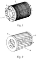
- Figure 1 of the drawings shows a completed core (which is the rotor in a finished motor) and Figure 2 shows the cage remaining after the laminations have been etched away.
- the cage is required to have sufficient structural strength to hold the stack of laminations tightly in position during use of the motor, to have good electrical conductivity and to be relatively inexpensive to manufacture.
- a method of manufacturing a core for an electric machine comprises forming a plurality of laminations, each having a plurality of slots, each slot being located at or near to the periphery of the lamination, positioning the laminations in a stack with the slots of the laminations in alignment to provide at least one elongated space extending through the stack, injecting thixotropic material into the space and allowing the material to set to form a cage, the stack of laminations being held together by the cage to provide the core.
- End rings are also formed, one at each end of the stack, from the thixotropic material, said rings also forming part of the cage.
- the injection is preferably carried out at a temperature below the solidus temperature of the material.
- Suitable thixotropic materials include copper/metal alloys, copper/non-metal alloys, aluminium/metal alloys and aluminium/non-metal alloys.
- EP-B-0305375 One method of manufacturing a thixotropic material suitable for use in the present invention is disclosed in EP-B-0305375.
- a rotor core for an electric machine comprises a stack of laminations and a cage formed from thixotropic material.
- the figures show a conventional configuration of the core rotor 1 of an induction motor formed of laminations 2 and a cage 3.
- Each lamination 2 is stamped or punched from electrical steel sheet so as to have a disc shape with a central aperture for fitment to a shaft and a plurality of radially-extending slots, in this embodiment twelve.
- the core of the invention has a similar shape and configuration to that of a conventional core
- the required number of laminations are placed together to form a stack with the slots in alignment, skewed relative to the axis.
- the stack is then placed in a press and a slug of material with a non-dendritic micro-structure is placed on a ram on one of the platens of the press and heated into the semi-solid state.
- the material shows the property of shear thinning, i e when a shear force is applied it flows.
- the press and ram is operated so that the slug of material is forced into the spaces formed by the plurality of slots in the stack and end ring moulds provided at each end.
- the material flows to fill the spaces thus forming the conductors 4 and the moulds thus forming the end rings 5 in a non-turbulent manner.
- the material is a non-dendritic alloy of copper and cuprous oxide, the alloy containing less than 1% oxygen when in solid solution, manufactured e.g. by the method disclosed in EP-B-0305375.
- the core so formed is removed from the press and then passed on to subsequent conventional motor manufacturing stages.
- the material flows to form a cage in a non-turbulent manner, compared with the turbulent flow of material during die-casting, the likelihood of the formation of defects such as porosity and laps which would otherwise adversely affect the conductivity and structural integrity is much reduced.
- the material is not heated to its melting temperature, the energy requirement is less, being of the order of 65% of the energy required to melt the material.
- the cost of the plant required for the method according to the invention is less than that for the plant required for high pressure die casting, because of the lower heat energy requirements and also because the thixoforming may be carried out with lower pressures compared with high pressure die casting.
- the cost of the dies will be less expensive due to the lower pressures and thus instead of using expensive high grade steel, for example, the die materials usable include mild steel, graphite and aluminium or copper alloys.
Landscapes
- Engineering & Computer Science (AREA)
- Mechanical Engineering (AREA)
- Power Engineering (AREA)
- Chemical & Material Sciences (AREA)
- Materials Engineering (AREA)
- Metallurgy (AREA)
- Organic Chemistry (AREA)
- Manufacturing & Machinery (AREA)
- Induction Machinery (AREA)
- Manufacture Of Motors, Generators (AREA)
Applications Claiming Priority (2)
| Application Number | Priority Date | Filing Date | Title |
|---|---|---|---|
| GB9322401 | 1993-10-29 | ||
| GB939322401A GB9322401D0 (en) | 1993-10-29 | 1993-10-29 | Electric machine |
Publications (1)
| Publication Number | Publication Date |
|---|---|
| EP0651496A1 true EP0651496A1 (de) | 1995-05-03 |
Family
ID=10744379
Family Applications (1)
| Application Number | Title | Priority Date | Filing Date |
|---|---|---|---|
| EP94307832A Withdrawn EP0651496A1 (de) | 1993-10-29 | 1994-10-25 | Elektrische Maschine |
Country Status (3)
| Country | Link |
|---|---|
| EP (1) | EP0651496A1 (de) |
| CA (1) | CA2134638A1 (de) |
| GB (3) | GB9322401D0 (de) |
Citations (6)
| Publication number | Priority date | Publication date | Assignee | Title |
|---|---|---|---|---|
| FR2089314A5 (de) * | 1970-04-07 | 1972-01-07 | Gen Motors Corp | |
| GB2037634A (en) * | 1978-11-27 | 1980-07-16 | Secretary Industry Brit | Casting thixotropic material |
| EP0080787A2 (de) * | 1981-12-01 | 1983-06-08 | The Dow Chemical Company | Verfahren zum Herstellen einer metallischen Flüssig-Fest-Mischung |
| GB2156855A (en) * | 1984-04-06 | 1985-10-16 | Nat Res Dev | Alloying process |
| WO1987006957A1 (en) * | 1986-05-12 | 1987-11-19 | The University Of Sheffield | Thixotropic materials |
| US4760300A (en) * | 1985-07-05 | 1988-07-26 | Mitsubishi Denki Kabushiki Kaisha | Squirrel-cage type rotor and method for its manufacture |
-
1993
- 1993-10-29 GB GB939322401A patent/GB9322401D0/en active Pending
-
1994
- 1994-10-25 EP EP94307832A patent/EP0651496A1/de not_active Withdrawn
- 1994-10-25 GB GB9421449A patent/GB9421449D0/en active Pending
- 1994-10-28 GB GB9421741A patent/GB2283372B/en not_active Expired - Fee Related
- 1994-10-28 CA CA002134638A patent/CA2134638A1/en not_active Abandoned
Patent Citations (6)
| Publication number | Priority date | Publication date | Assignee | Title |
|---|---|---|---|---|
| FR2089314A5 (de) * | 1970-04-07 | 1972-01-07 | Gen Motors Corp | |
| GB2037634A (en) * | 1978-11-27 | 1980-07-16 | Secretary Industry Brit | Casting thixotropic material |
| EP0080787A2 (de) * | 1981-12-01 | 1983-06-08 | The Dow Chemical Company | Verfahren zum Herstellen einer metallischen Flüssig-Fest-Mischung |
| GB2156855A (en) * | 1984-04-06 | 1985-10-16 | Nat Res Dev | Alloying process |
| US4760300A (en) * | 1985-07-05 | 1988-07-26 | Mitsubishi Denki Kabushiki Kaisha | Squirrel-cage type rotor and method for its manufacture |
| WO1987006957A1 (en) * | 1986-05-12 | 1987-11-19 | The University Of Sheffield | Thixotropic materials |
Non-Patent Citations (2)
| Title |
|---|
| M.C.FLEMINGS: "behavior of Metal Alloys in the Semisolid State", METALLURGICAL TRANSACTIONS B. PROCESS METALLURGY, vol. 22B, no. 3, June 1991 (1991-06-01), NEW YORK US, pages 287 - 290, XP000249543 * |
| P.S.FREDERICK, N.L.BRADLEY AND S.C.ERICKSON: "injection molding magnesium alloys", ADVANCED MATERIALS & PROCESSES. (INC. METAL PROGRESS), vol. 134, no. 4, October 1988 (1988-10-01), METALS PARK, OHIO US, pages 53 - 56, XP000020482 * |
Also Published As
| Publication number | Publication date |
|---|---|
| CA2134638A1 (en) | 1995-04-30 |
| GB9421449D0 (en) | 1994-12-07 |
| GB9421741D0 (en) | 1994-12-14 |
| GB2283372A (en) | 1995-05-03 |
| GB9322401D0 (en) | 1993-12-15 |
| GB2283372B (en) | 1997-02-05 |
Similar Documents
| Publication | Publication Date | Title |
|---|---|---|
| US20100007234A1 (en) | Squirrel-cage rotors and methods of manufacturing same | |
| US4760300A (en) | Squirrel-cage type rotor and method for its manufacture | |
| US8925182B2 (en) | Cast rotor and method | |
| EP0633649B1 (de) | Verfahren und vorrichtung zur erstellung eines käfigläufers eines induktionsmotors | |
| CN109004802B (zh) | 一种转子加工工艺 | |
| EP2920868B1 (de) | Giesstechnologie für induktionsrotoranordnungen | |
| AU2014201466B2 (en) | Induction Motor and Manufacturing Method Thereof | |
| JPH09314301A (ja) | 軽合金製ホイールハブ類の製造方法 | |
| DE102009034647A1 (de) | Herstellungsverfahren für Käfigläufer | |
| US20070210667A1 (en) | Squirrel-cage rotor | |
| GB2283372A (en) | Core construction using conductive thixotropic material to form a cage winding | |
| US1777320A (en) | Rotor | |
| EP2866335A2 (de) | Rotor mit Sicherungsringen für eine Asynchronmaschine sowie Verfahren zum Fertigen derselben | |
| DE102005030797A1 (de) | Käfigläufer einer Induktionsmaschine | |
| JP3079853B2 (ja) | かご形回転子の低圧鋳造方法 | |
| KR100434289B1 (ko) | 농형 유도전동기의 회전자 | |
| US20240146163A1 (en) | Method for producing a squirrel-cage rotor with coated cage ring | |
| JPH1141872A (ja) | 電動機の回転子 | |
| JP3246240B2 (ja) | かご形回転電機の製造方法 | |
| JPS5910159A (ja) | ダイカストロ−タ用鉄心の製作方法 | |
| JP3479932B2 (ja) | かご型ロータの製造方法 | |
| US1773739A (en) | Rotor | |
| JPS6240040A (ja) | かご形回転子の製造装置 | |
| EP4718693A1 (de) | Käfigläufer, verfahren zur herstellung eines käfigläufers durch giessen, und satz von giessformen zur durchführung des verfahrens | |
| JP3479929B2 (ja) | モータ用ステ−タコアの固定方法およびその装置 |
Legal Events
| Date | Code | Title | Description |
|---|---|---|---|
| PUAI | Public reference made under article 153(3) epc to a published international application that has entered the european phase |
Free format text: ORIGINAL CODE: 0009012 |
|
| AK | Designated contracting states |
Kind code of ref document: A1 Designated state(s): DE FR GB IT SE |
|
| STAA | Information on the status of an ep patent application or granted ep patent |
Free format text: STATUS: THE APPLICATION IS DEEMED TO BE WITHDRAWN |
|
| 18D | Application deemed to be withdrawn |
Effective date: 19951104 |