EP0651545B1 - Radiotéléphone portable ayant une partie du récepteur mobile - Google Patents
Radiotéléphone portable ayant une partie du récepteur mobile Download PDFInfo
- Publication number
- EP0651545B1 EP0651545B1 EP94307734A EP94307734A EP0651545B1 EP 0651545 B1 EP0651545 B1 EP 0651545B1 EP 94307734 A EP94307734 A EP 94307734A EP 94307734 A EP94307734 A EP 94307734A EP 0651545 B1 EP0651545 B1 EP 0651545B1
- Authority
- EP
- European Patent Office
- Prior art keywords
- telephone
- receiver
- telephone body
- portable telephone
- panel
- Prior art date
- Legal status (The legal status is an assumption and is not a legal conclusion. Google has not performed a legal analysis and makes no representation as to the accuracy of the status listed.)
- Expired - Lifetime
Links
Images






Classifications
-
- H—ELECTRICITY
- H04—ELECTRIC COMMUNICATION TECHNIQUE
- H04M—TELEPHONIC COMMUNICATION
- H04M1/00—Substation equipment, e.g. for use by subscribers
- H04M1/02—Constructional features of telephone sets
- H04M1/03—Constructional features of telephone transmitters or receivers, e.g. telephone hand-sets
-
- H—ELECTRICITY
- H04—ELECTRIC COMMUNICATION TECHNIQUE
- H04B—TRANSMISSION
- H04B1/00—Details of transmission systems, not covered by a single one of groups H04B3/00 - H04B13/00; Details of transmission systems not characterised by the medium used for transmission
- H04B1/38—Transceivers, i.e. devices in which transmitter and receiver form a structural unit and in which at least one part is used for functions of transmitting and receiving
- H04B1/3827—Portable transceivers
- H04B1/3833—Hand-held transceivers
-
- H—ELECTRICITY
- H04—ELECTRIC COMMUNICATION TECHNIQUE
- H04B—TRANSMISSION
- H04B1/00—Details of transmission systems, not covered by a single one of groups H04B3/00 - H04B13/00; Details of transmission systems not characterised by the medium used for transmission
- H04B1/38—Transceivers, i.e. devices in which transmitter and receiver form a structural unit and in which at least one part is used for functions of transmitting and receiving
- H04B1/3827—Portable transceivers
- H04B1/3833—Hand-held transceivers
- H04B1/3838—Arrangements for reducing RF exposure to the user, e.g. by changing the shape of the transceiver while in use
-
- H—ELECTRICITY
- H04—ELECTRIC COMMUNICATION TECHNIQUE
- H04M—TELEPHONIC COMMUNICATION
- H04M1/00—Substation equipment, e.g. for use by subscribers
- H04M1/02—Constructional features of telephone sets
- H04M1/0202—Portable telephone sets, e.g. cordless phones, mobile phones or bar type handsets
-
- H—ELECTRICITY
- H04—ELECTRIC COMMUNICATION TECHNIQUE
- H04M—TELEPHONIC COMMUNICATION
- H04M1/00—Substation equipment, e.g. for use by subscribers
- H04M1/02—Constructional features of telephone sets
- H04M1/0202—Portable telephone sets, e.g. cordless phones, mobile phones or bar type handsets
- H04M1/0206—Portable telephones comprising a plurality of mechanically joined movable body parts, e.g. hinged housings
- H04M1/0208—Portable telephones comprising a plurality of mechanically joined movable body parts, e.g. hinged housings characterized by the relative motions of the body parts
- H04M1/0235—Slidable or telescopic telephones, i.e. with a relative translation movement of the body parts; Telephones using a combination of translation and other relative motions of the body parts
- H04M1/0237—Sliding mechanism with one degree of freedom
Definitions
- the present invention relates to portable telephones and, particularly to a portable telephone having a movable portion.
- Radio communication system devices such as mobile telephones, personal radio transceivers and portable telephones, in particular, of a stationary type, a shoulder type or a handy type are now commercially available on the market.
- Figure 1 shows an example of a portable telephone that is now in general use. While personal transceivers make a communication by using the 90 MHz band, mobile telephones and portable telephones make a communication by using the 800 MHz band and antennas of the mobile telephone and the portable telephone are relatively short in length.
- reference numeral 1 generally depicts a portable telephone which is of a handy type cordless telephone.
- this portable telephone 1 includes an outer casing 2 of a rectangular box configuration made of synthetic resin.
- the outer casing 2 includes a front panel 2a, and the front panel 2a has a receiver 3 provided on its upper end face so as to be housed in the outer casing 2.
- the telephone 1 includes an operation key group 4 disposed at its substantially central position.
- the operation key group 4 includes a plurality of operation keys, such as ten keys or the like.
- the telephone 1 includes a transmitter (microphone) 5 provided on its lower surface side so as to be housed in the outer casing 2.
- the telephone 1 includes an antenna 6 upwardly extended from the upper surface portion of the outer casing 2.
- Some portable telephones include a liquid crystal display (LCD) unit provided on the front panel 2a of the outer casing 2 in order to display information entered by the user, though not shown.
- LCD liquid crystal display
- the portable telephone 1 thus arranged includes the receiver 3 and the transmitter 5 both of which are housed within the outer casing 2. Therefore, the outer casing 2 has to be long enough to the extent that it can substantially cover the length between the user's ears and mouth. As a result, the whole portable telephone 1 becomes too large in size to be put into user's suitable carrying means, such as a purse or the like.
- a portable telephone which includes a telephone body composed of two telephone body portions joined by a hinge. These two telephone body portions are rotated to open when this portable telephone is in use.
- DE-A-34,01,518 discloses a telephone having three body portions hinged together.
- a portable telephone having a miniaturised telephone body, i.e., a short-length outer casing.
- a part of the outer casing can be slid upwardly along the longitudinal direction of the outer casing such that a length between the receiver and the transmitter housed in the lower portion of the outer casing can substantially be agreed with a length between the user's ears and mouth.
- Such a telephone is described in EP-A-0,535,903.
- the outer casing of the telephone body is reduced in length, it is unavoidable that the antenna that is provided on the telephone body is made close to the user's body when the portable telephone is in use.
- a telephone call is made, if the antenna of the portable telephone is placed too close to the user's body, then a bad influence is exerted upon a radio radiation characteristic and a telephone call is disturbed by a noise accordingly.
- the present invention provides a portable telephone as defined in the appended claims.
- the telephone body may include the transmitter attached to one end thereof and the antenna attached to the other end thereof.
- the receiver may be disposed on the other end of the telephone body.
- the supporting mechanism may support the receiver such that the receiver is projected from the telephone body not only in the direction away from the antenna but also with a predetermined angle with respect to the longitudinal direction of the telephone body. That is, the receiver may be displaced both laterally and longitudinally of the telephone.
- the portable telephone may include a display unit and have at least one aperture defined on one side surface thereof so as to communicate with the transmitter.
- the display unit may be disposed on one side surface of the telephone body and at least a part of the display unit may be covered with the receiver unit when the portable telephone is in the telephone call standby mode or is retracted.
- the receiver portion is projected from the telephone body when a telephone call is made, the user can reliably hold the receiver portion on the ear while putting the mouth close to the transmitter of the telephone body. Thus, it is possible to improve an acoustic characteristic. Further, since the receiver unit is projected from the telephone body, the antenna of the telephone becomes distant from the user's body. Thus, it is possible to improve a radio radiation characteristic. Therefore, the user can make a satisfactory telephone communication.
- the receiver and transmitter may each be split so that circuitry remains in the telephone body and only the transducer, or means for emanating or receiving the sound, are at the ends or in the moving part of the telephone.
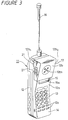
- the portable telephone includes a telephone body 11.
- the telephone body 11 includes an outer casing 12 of a rectangular box configuration having a front panel 12a.
- the front panel 12a is curved in a substantially L-letter fashion as seen from the side.
- the front panel 12a includes a plurality of operation keys 13, such as ten keys or the like, disposed on its lower half portion.
- the front panel 12 includes a transmitter (microphone) 14 disposed on its lower surface side so as to be housed within the outer casing 2.
- the front panel 12a includes a display unit 15 formed of a liquid crystal display (LCD) device disposed on its upper half portion near the centre.
- the display unit 15 can display information or the like entered when the user operates the operation keys 13.
- the portable telephone has an antenna 16 upwardly extended from the upper surface portion of the outer casing 12.
- the front panel 12a includes a plurality of apertures 12c defined on its lower end at the position corresponding to the position at which the transmitter 14 is housed. User's voice is introduced into the transmitter 14 through the apertures 12c.
- the outer casing 12 includes the front panel 12a and the front panel 12a includes a sub-panel 12b supported to its upper surface side of the upper half portion by a supporting mechanism, which will be described later on, such that the sub-panel 12b can be moved in the front upper oblique direction.
- the sub-panel 12b includes a receiver 17 attached to its inner surface side.
- the sub-panel 12b includes a plurality of apertures 12b3 defined at its position corresponding to the position at which the receiver 17 is housed. User's voice emanated from the receiver 17 is output to the outside through the apertures 12b3.
- a supporting mechanism that supports the sub-panel 12b to the front panel 12a is composed of a pair of rotating arms 18 as shown in Figures 4 and 5.
- the front panel 12a includes a pair of upper and lower rotating arms 18 attached to the upper portion of the respective side surfaces of its upper half portion such that the rotating arms 18 can be freely rotated at their one ends.
- the other ends of the rotating arms 18 are attached to the sub-panel 12b at its respective side surface portions 12b1, 12b2 inwardly facing the respective side surfaces of the front panel 12a.
- the sub-panel 12b is moved by the rotating arms 18 in parallel to the front panel 12a and the sub-panel 12b can be projected in the front upper oblique direction of the front panel 12a.
- the sub-panel 12b is permitted to move in a range defined when the rotating arms 18 abut against first and second engagement portions 19a, 19b formed on the side surfaces of the front panel 12a.
- the rotating arm 18 abuts against the first engagement portion 19a and is engaged with the first engagement portion 19a in alignment with the longitudinal direction of the front panel 12a at the position in which the sub-panel 12b overlaps the front panel 12a.
- the rotating arm 18 abuts against the second engagement portion 19b and is engaged with the second engagement portion 19b at the position in which the sub-panel 12b is projected in the front upper oblique direction of the front panel 12a.
- the rotating arms 18 can be rotated in the range defined when they are engaged with the first and second engagement portions 19a, 19b as described above.
- a rotational angle ⁇ defined when the rotating arm 18 is engaged with the second engagement portion 19b after the rotating arm 18 was engaged with the first engagement portion 19a is set to an obtuse angle as shown by a two-dot chain line in Figure 5.
- the rotating arms 18 are supported under spring force of pressing spring member, such as a leaf spring 20.
- the sub-panel 12b is composed of the side surface portions 12b1, 12b2 which are located outside the side surfaces of the front panel 12a.
- a thickness of each of the side surface portions 12b1, 12b2 is selected to be nearly equal to or somewhat greater than a height obtained when an operation button 21, such as a volume button disposed on the side surface of the outer casing 12, is projected from the side surface of the front panel 12a.
- an operation button 21 such as a volume button disposed on the side surface of the outer casing 12
- the operation button 21 is located in the range in which the side surface portions 12b1, 12b2 are large in thickness. As a consequence, the operation button 21 becomes difficult to handle. If the sub-panel 12b is projected relative to the front panel 12a and located at the position in which the portable telephone can be used, then it becomes possible to handle the operation button 21 normally.
- the sub-panel 12b can cover the display unit 15 disposed on the front panel 12a so as to leave a predetermined display portion 15a exposed when the sub-panel 12b is placed at the retracted position relative to the front panel 12a.
- the display unit 15 constantly displays necessary items of information on its display portion 15a that is not covered with the sub-panel 12b.
- the sub-panel 12b having the receiver 17 is overlapped on the upper half portion of the front panel 12a and placed at the retracted position.
- the portable telephone is reduced in length on the whole and looks compact.
- the sub-panel 12b When the portable telephone is in use (telephone call is made), the sub-panel 12b is pushed relative to the front panel 12a so as to project in the front upper direction through the rotating arms 18. At that time, the rotating arm 18 is urged against the second engagement portion 19b.
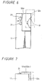
- the receiver 17 is moved upwardly along a line b inclined by a predetermined angle from a line a of the longitudinal direction of the telephone body 11.
- the user contacts the receiver 17 with an auricle e under the condition that the user keeps the transmitter 14 housed in the telephone body 11, i.e., lower portion of the outer casing 12 close to user's mouth m of a human body M . More precisely, the user can move the receiver 17 to the position opposing the auricle e when the sub-panel 12b is brought in contact with the auricle e . Thus, the user can make a very good telephone call with an improved acoustic characteristic. In this condition, because the antenna 16 upwardly extended from the upper surface portion of the outer casing 12 is made distant from the human body M , it is possible to improve a radio radiation characteristic. Thus, the user can make a very good telephone call.
- the rotating arm 18 is rotated by the predetermined obtuse angle ⁇ and abuts against the second engagement portion 19b, whereby the receiver 17 can stably be brought in close contact with the auricle e . Therefore, the receiver 17 can be prevented from being returned to the original position inadvertently.
- the display unit 15a on the front panel 12a is covered with the sub-panel 12b except the display portion 15a on which displayed items are constantly displayed.
- the user can know clearly that the receiver 17 is not placed at the telephone call position and that a telephone call can be inhibited from being made.
- it is possible to prevent the user from operating the portable telephone wrongly.
- the operation button 21 becomes difficult to handle. Therefore, it is possible for the user to confirm the disabled state of the portable telephone from a visual standpoint and also from a feeling standpoint. Thus, the user can be prevented from operating the portable telephone wrongly and the user can gain a better understanding of how to operate the portable telephone with ease.
- the operation button 21 is used as a volume button to control volume of alert sound representing an incoming call, then it becomes possible to prevent the volume button from being depressed inadvertently.
- the present invention is not limited thereto and the sub-panel 12b may not prevent the user from operating the portable telephone wrongly but can move the receiver.
- the present invention is not limited thereto and can take a method of sliding the sub-panel 12b along a guide groove defined between the telephone body 11 and an attachment member to which the receiver 17 is attached, such as the sub-panel 12b or a method of sliding the sub-panel 12b in a click fashion.
- a front panel of a telephone body 31 is shaped in plane unlike that of the telephone body 11 according to the first embodiment.
- the telephone body 31 includes a display unit 34 formed of a liquid crystal display device or the like provided on the upper portion of the centre of its front panel. Though not shown, the telephone body 31 includes a transmitter disposed on the inside of its lower portion.
- the telephone body 31 includes an operation unit 36 formed of a plurality of keys (not shown) disposed between the display unit 34 formed on its front panel and the transmitter.
- the telephone body 31 includes a sub-panel 33 attached to its upper side portion so as to become movable in the upper and lower direction.
- the sub-panel 33 includes a receiver 32 attached to its inner surface. As shown in Figure 9, the sub-panel 33 is supported by a supporting mechanism (not shown) such that, when the portable telephone is in use or a telephone call is made, the sub-panel 33 is projected from the front panel of the telephone body 31 in the forward direction and that the sub-panel 33 is projected from the upper end of the telephone body 31. When the portable telephone is not in use or the portable telephone is in the telephone call standby mode, the sub-panel 33 is accommodated in the telephone body 31 such that it is substantially flush with the front panel and the upper end of the telephone body 31.
- the portable telephone includes an antenna 35 upwardly projected from the upper end of its telephone body 31.
- the display unit 34 when the portable telephone is in the telephone call standby mode, the display unit 34 is covered with the sub-panel 33 except a part thereof (referred to hereinafter as "normal display portion 34a").
- the normal display portion 34a displays time and information representing telephone operation condition, such as POWER ON or the like.
- the sub-panel 33 in the normal state, the sub-panel 33 is projected from the telephone body 31 as described above so that the whole of the display unit 34 is exposed and can be visually confirmed from the outside. In this state, the display unit 34 displays received data and information entered by the operation unit 36 or the like.
- the receiver 33 is projected from the telephone body 31 by a small amount as compared with the first embodiment because the front panel of the telephone body 31 is made flat as compared with the first embodiment, in the state shown in Figure 10B, the receiver 35 is moved up to the position shown by a two-dot chain line in Figure 9 so that the antenna 35 can be made distant from the user's body similarly to Figure 8.
- the thickness of the telephone body 31 can be reduced as compared with the first embodiment.
- Figure 10A under the condition that a part of the display unit 34 is covered with the receiver 33 when the telephone is placed in the telephone call standby mode, the user can visually confirm that the operation unit 36 cannot be operated. Thus, the user can be prevented from operating the telephone wrongly.
- the telephone body can be arbitrarily changed in arrangement and structure and the supporting member, such as the panel having the receiver attached thereto, can also be changed in arrangement and shape in association therewith.
Landscapes
- Engineering & Computer Science (AREA)
- Signal Processing (AREA)
- Computer Networks & Wireless Communication (AREA)
- Telephone Set Structure (AREA)
- Mobile Radio Communication Systems (AREA)
Claims (8)
- Téléphone portatif comprenant :un corps de téléphone (11) comportant un émetteur (14) et une antenne (16) qui y est fixée et une première surface latérale ;un récepteur (17); etun mécanisme support (12b, 18) auquel est fixé ledit récepteur et supportant ledit récepteur de façon que ledit récepteur puisse se déplacer librement entre une position rétractée dans laquelle lui-même et ledit mécanisme support sont logés dans ledit corps de téléphone et une position en saillie dans laquelle ledit récepteur fait saillie à l'extérieur dudit corps de téléphone, ladite position en saillie étant décalée par rapport à ladite position rétractée dans les directions parallèle et perpendiculaire à ladite première surface latérale en s'écartant dudit émetteur, ledit mécanisme support comprenant au moins un bras fixé de manière pivotante audit corps de téléphone.
- Téléphone portatif selon la revendication 1, dans lequel ledit corps de téléphone comprend plusieurs touches de mise en oeuvre disposées sur sa dite première surface latérale et comprend aussi au moins une ouverture définie sur ladite première surface latérale de façon à communiquer avec ledit émetteur, ledit récepteur étant fixé à ladite première surface latérale dudit corps de téléphone par ledit mécanisme support.
- Téléphone portatif selon la revendication 1 ou 2, dans lequel ledit corps de téléphone comprend un module d'affichage disposé dans une position telle qu'une partie dudit module d'affichage est recouverte par ledit mécanisme support lorsque ledit récepteur est rétracté.
- Téléphone portatif selon la revendication 1, 2, ou 3, dans lequel ladite partie comportant ledit récepteur fait saillie dudit corps de téléphone par la rotation dudit bras, d'un angle obtus.
- Téléphone portatif selon la revendication 1, 2, 3 ou 4, dans lequel ledit mécanisme support comprend au moins une paire de tels bras fixés de manière pivotante audit corps de téléphone.
- Téléphone portatif selon la revendication 1, 2, 3, 4 ou 5, dans lequel ledit corps de téléphone comprend au moins une touche de mise en oeuvre en saillie depuis sa dite première surface latérale, ledit mécanisme support comprend un élément de fixation auquel est fixé ledit récepteur, et l'épaisseur de la surface latérale dudit élément de fixation est plus grande que la hauteur dudit bouton de mise en oeuvre en saillie au-dessus de ladite première surface latérale dudit corps de téléphone.
- Téléphone portatif selon l'une quelconque des revendications précédentes, dans lequel le mécanisme support supporte ledit récepteur de façon telle que, lorsque ledit récepteur est dans la position en saillie, il est incliné à un angle prédéterminé par rapport à l'axe longitudinal dudit corps de téléphone.
- Téléphone portatif selon la revendication 7, dans lequel ledit récepteur est fixé à ladite première surface latérale dudit corps de téléphone par ledit mécanisme support dans la même direction que la direction dans laquelle ledit émetteur est fixé audit corps de téléphone.
Applications Claiming Priority (2)
| Application Number | Priority Date | Filing Date | Title |
|---|---|---|---|
| JP5272794A JPH07131848A (ja) | 1993-10-29 | 1993-10-29 | 携帯用電話機 |
| JP272794/93 | 1993-10-29 |
Publications (2)
| Publication Number | Publication Date |
|---|---|
| EP0651545A1 EP0651545A1 (fr) | 1995-05-03 |
| EP0651545B1 true EP0651545B1 (fr) | 1998-12-16 |
Family
ID=17518839
Family Applications (1)
| Application Number | Title | Priority Date | Filing Date |
|---|---|---|---|
| EP94307734A Expired - Lifetime EP0651545B1 (fr) | 1993-10-29 | 1994-10-21 | Radiotéléphone portable ayant une partie du récepteur mobile |
Country Status (5)
| Country | Link |
|---|---|
| US (1) | US5603100A (fr) |
| EP (1) | EP0651545B1 (fr) |
| JP (1) | JPH07131848A (fr) |
| CN (1) | CN1070679C (fr) |
| DE (1) | DE69415273T2 (fr) |
Families Citing this family (20)
| Publication number | Priority date | Publication date | Assignee | Title |
|---|---|---|---|---|
| JP2834012B2 (ja) * | 1994-11-08 | 1998-12-09 | 日本電気株式会社 | スピーカ収納型電話機 |
| JP3606498B2 (ja) * | 1996-04-26 | 2005-01-05 | 三菱電機株式会社 | 携帯情報端末装置 |
| US6073027A (en) * | 1996-08-29 | 2000-06-06 | Bellsouth Corporation | Portable radiotelephone with sliding cover and automatic antenna extension |
| JPH1093668A (ja) | 1996-09-19 | 1998-04-10 | Nec Corp | 携帯無線機 |
| USD440546S1 (en) | 1998-11-30 | 2001-04-17 | Sony Corporation | Wireless telephone |
| USD421006S (en) * | 1998-12-30 | 2000-02-22 | Sony Corporation | Wireless telephone |
| GB2347577B (en) * | 1999-03-02 | 2003-02-19 | Ericsson Telefon Ab L M | Telephone handset with pivotable portion |
| US6484020B1 (en) | 2000-09-01 | 2002-11-19 | Nokia Mobile Phones Ltd. | Portable communication device with a deployable ear bud |
| GB2366476A (en) * | 2000-09-05 | 2002-03-06 | Diran Hoonanian | A safer mobile phone |
| KR100785694B1 (ko) * | 2001-09-20 | 2007-12-14 | 엘지전자 주식회사 | 개인휴대단말기 |
| JP2003204383A (ja) | 2001-10-26 | 2003-07-18 | Nec Corp | 携帯電話機 |
| JP4357900B2 (ja) * | 2003-08-18 | 2009-11-04 | 加藤電機株式会社 | 小型情報端末用スライドヒンジ |
| US8095073B2 (en) * | 2004-06-22 | 2012-01-10 | Sony Ericsson Mobile Communications Ab | Method and apparatus for improved mobile station and hearing aid compatibility |
| KR100663620B1 (ko) * | 2005-02-05 | 2007-01-02 | 엘지전자 주식회사 | 밀착형 리시버 장식구를 갖는 이동통신단말기 |
| US7565720B1 (en) * | 2005-04-01 | 2009-07-28 | Apple Inc. | Hinge mechanism with clutching function |
| US7428431B2 (en) | 2005-07-06 | 2008-09-23 | Kyocera Wireless Corp. | Extendable antenna and speaker box |
| KR100702857B1 (ko) * | 2005-12-19 | 2007-04-03 | 삼성전자주식회사 | 휴대용 단말기의 스피커 모듈 |
| US9384672B1 (en) * | 2006-03-29 | 2016-07-05 | Amazon Technologies, Inc. | Handheld electronic book reader device having asymmetrical shape |
| JP4720678B2 (ja) * | 2006-08-25 | 2011-07-13 | 日本電気株式会社 | 携帯電話装置 |
| JP2011124964A (ja) * | 2009-12-14 | 2011-06-23 | Shinji Abiru | 携帯電話 |
Citations (1)
| Publication number | Priority date | Publication date | Assignee | Title |
|---|---|---|---|---|
| EP0647037A1 (fr) * | 1993-09-30 | 1995-04-05 | Nec Corporation | Appareil radio portatif et pliable |
Family Cites Families (13)
| Publication number | Priority date | Publication date | Assignee | Title |
|---|---|---|---|---|
| DE3401518A1 (de) * | 1984-01-18 | 1985-07-25 | Ant Nachrichtentech | Tragbares funktelefon |
| JPS6156524A (ja) * | 1984-08-28 | 1986-03-22 | Fujitsu Ltd | 携帯型無線機 |
| JPH02261224A (ja) * | 1989-03-31 | 1990-10-24 | Mitsubishi Electric Corp | 携帯無線機 |
| JPH038149A (ja) * | 1989-06-06 | 1991-01-16 | Sumitomo Metal Mining Co Ltd | 光磁気ディスク |
| GB2235850A (en) * | 1989-08-22 | 1991-03-13 | Plessey Co Plc | Telephone handset |
| GB2235606B (en) * | 1989-08-24 | 1994-03-30 | Technophone Ltd | Portable telephone |
| JPH03175826A (ja) * | 1989-12-05 | 1991-07-30 | Matsushita Electric Ind Co Ltd | 携帯形電話機 |
| JP2689785B2 (ja) * | 1991-09-30 | 1997-12-10 | 日本電気株式会社 | 小型携帯無線機 |
| JPH0661910A (ja) * | 1992-04-21 | 1994-03-04 | Nec Corp | 携帯電話装置 |
| JPH0645982A (ja) * | 1992-07-22 | 1994-02-18 | Sony Corp | 携帯型無線電話機 |
| JPH0685730A (ja) * | 1992-09-04 | 1994-03-25 | Sony Corp | 携帯無線電話機 |
| JP3457351B2 (ja) * | 1992-09-30 | 2003-10-14 | 株式会社東芝 | 携帯無線装置 |
| JP2979871B2 (ja) * | 1992-12-18 | 1999-11-15 | 日本電気株式会社 | 携帯電話機 |
-
1993
- 1993-10-29 JP JP5272794A patent/JPH07131848A/ja active Pending
-
1994
- 1994-10-21 EP EP94307734A patent/EP0651545B1/fr not_active Expired - Lifetime
- 1994-10-21 DE DE69415273T patent/DE69415273T2/de not_active Expired - Fee Related
- 1994-10-21 US US08/326,936 patent/US5603100A/en not_active Expired - Fee Related
- 1994-10-28 CN CN94113771A patent/CN1070679C/zh not_active Expired - Fee Related
Patent Citations (1)
| Publication number | Priority date | Publication date | Assignee | Title |
|---|---|---|---|---|
| EP0647037A1 (fr) * | 1993-09-30 | 1995-04-05 | Nec Corporation | Appareil radio portatif et pliable |
Also Published As
| Publication number | Publication date |
|---|---|
| JPH07131848A (ja) | 1995-05-19 |
| DE69415273D1 (de) | 1999-01-28 |
| EP0651545A1 (fr) | 1995-05-03 |
| US5603100A (en) | 1997-02-11 |
| CN1114490A (zh) | 1996-01-03 |
| DE69415273T2 (de) | 1999-06-02 |
| CN1070679C (zh) | 2001-09-05 |
| HK1013564A1 (en) | 1999-08-27 |
Similar Documents
| Publication | Publication Date | Title |
|---|---|---|
| EP0651545A1 (fr) | Radiotéléphone portable ayant une partie du récepteur mobile | |
| EP1057311B1 (fr) | Montage du type charniere pour appareils electroniques | |
| US7983628B2 (en) | Cellular telephone and personal digital assistant | |
| US6934568B2 (en) | Extending hinged flip apparatus for a communication device | |
| EP0883956B1 (fr) | Radio telephone | |
| US20090017875A1 (en) | Cellular telephone and personal digital assistant | |
| KR20010021133A (ko) | 정보단말기 | |
| US6850773B1 (en) | Antenna system for a wrist communication device | |
| JP2867863B2 (ja) | 携帯無線機 | |
| AU774812B2 (en) | A wrist communication device having multi-sectioned keypad and antenna system | |
| HK1013564B (en) | Hand held radiotelephone with moveable receiver portion | |
| KR0133145B1 (ko) | 안테나를 이용한 손목착용용 무선전화기의 수신 및 발신장치 및 그 제어방법 | |
| JP3065200B2 (ja) | 携帯用無線装置 | |
| JP2766074B2 (ja) | 携帯電話機 | |
| JP3304627B2 (ja) | 携帯用無線電話機 | |
| KR200198286Y1 (ko) | 무선 단말기의 디스플레이 커버 | |
| JPH07212822A (ja) | 携帯型電話機 | |
| KR20050070219A (ko) | 휴대용 단말기의 개폐장치 | |
| JPH1098514A (ja) | 移動体通信装置 | |
| NZ531324A (en) | A wrist communication device having a wireless connection with a multi-sectioned keypad | |
| JP2002176482A (ja) | 携帯電話機 |
Legal Events
| Date | Code | Title | Description |
|---|---|---|---|
| PUAI | Public reference made under article 153(3) epc to a published international application that has entered the european phase |
Free format text: ORIGINAL CODE: 0009012 |
|
| AK | Designated contracting states |
Kind code of ref document: A1 Designated state(s): DE FR GB |
|
| 17P | Request for examination filed |
Effective date: 19951010 |
|
| 17Q | First examination report despatched |
Effective date: 19951127 |
|
| GRAG | Despatch of communication of intention to grant |
Free format text: ORIGINAL CODE: EPIDOS AGRA |
|
| GRAG | Despatch of communication of intention to grant |
Free format text: ORIGINAL CODE: EPIDOS AGRA |
|
| GRAH | Despatch of communication of intention to grant a patent |
Free format text: ORIGINAL CODE: EPIDOS IGRA |
|
| GRAH | Despatch of communication of intention to grant a patent |
Free format text: ORIGINAL CODE: EPIDOS IGRA |
|
| GRAA | (expected) grant |
Free format text: ORIGINAL CODE: 0009210 |
|
| AK | Designated contracting states |
Kind code of ref document: B1 Designated state(s): DE FR GB |
|
| REF | Corresponds to: |
Ref document number: 69415273 Country of ref document: DE Date of ref document: 19990128 |
|
| ET | Fr: translation filed | ||
| PLBE | No opposition filed within time limit |
Free format text: ORIGINAL CODE: 0009261 |
|
| STAA | Information on the status of an ep patent application or granted ep patent |
Free format text: STATUS: NO OPPOSITION FILED WITHIN TIME LIMIT |
|
| 26N | No opposition filed | ||
| PGFP | Annual fee paid to national office [announced via postgrant information from national office to epo] |
Ref country code: FR Payment date: 20011010 Year of fee payment: 8 |
|
| PGFP | Annual fee paid to national office [announced via postgrant information from national office to epo] |
Ref country code: GB Payment date: 20011024 Year of fee payment: 8 |
|
| PGFP | Annual fee paid to national office [announced via postgrant information from national office to epo] |
Ref country code: DE Payment date: 20011105 Year of fee payment: 8 |
|
| REG | Reference to a national code |
Ref country code: GB Ref legal event code: IF02 |
|
| PG25 | Lapsed in a contracting state [announced via postgrant information from national office to epo] |
Ref country code: GB Free format text: LAPSE BECAUSE OF NON-PAYMENT OF DUE FEES Effective date: 20021021 |
|
| PG25 | Lapsed in a contracting state [announced via postgrant information from national office to epo] |
Ref country code: DE Free format text: LAPSE BECAUSE OF NON-PAYMENT OF DUE FEES Effective date: 20030501 |
|
| GBPC | Gb: european patent ceased through non-payment of renewal fee |
Effective date: 20021021 |
|
| PG25 | Lapsed in a contracting state [announced via postgrant information from national office to epo] |
Ref country code: FR Free format text: LAPSE BECAUSE OF NON-PAYMENT OF DUE FEES Effective date: 20030630 |
|
| REG | Reference to a national code |
Ref country code: FR Ref legal event code: ST |