EP0651954B1 - Spannvorrichtung für einen Sportschuh - Google Patents
Spannvorrichtung für einen Sportschuh Download PDFInfo
- Publication number
- EP0651954B1 EP0651954B1 EP19930890219 EP93890219A EP0651954B1 EP 0651954 B1 EP0651954 B1 EP 0651954B1 EP 19930890219 EP19930890219 EP 19930890219 EP 93890219 A EP93890219 A EP 93890219A EP 0651954 B1 EP0651954 B1 EP 0651954B1
- Authority
- EP
- European Patent Office
- Prior art keywords
- rotational body
- axial
- base part
- recess
- cable
- Prior art date
- Legal status (The legal status is an assumption and is not a legal conclusion. Google has not performed a legal analysis and makes no representation as to the accuracy of the status listed.)
- Expired - Lifetime
Links
- 230000000903 blocking effect Effects 0.000 claims description 9
- 230000004323 axial length Effects 0.000 claims 1
- 238000007373 indentation Methods 0.000 claims 1
- 210000003423 ankle Anatomy 0.000 description 2
- 238000010276 construction Methods 0.000 description 2
- 230000008878 coupling Effects 0.000 description 2
- 238000010168 coupling process Methods 0.000 description 2
- 238000005859 coupling reaction Methods 0.000 description 2
- 239000002184 metal Substances 0.000 description 2
- 230000006978 adaptation Effects 0.000 description 1
- 230000000386 athletic effect Effects 0.000 description 1
- 238000013270 controlled release Methods 0.000 description 1
- 239000010985 leather Substances 0.000 description 1
- 239000000463 material Substances 0.000 description 1
- 239000006187 pill Substances 0.000 description 1
- 239000004033 plastic Substances 0.000 description 1
- 238000004804 winding Methods 0.000 description 1
Images


Classifications
-
- A—HUMAN NECESSITIES
- A43—FOOTWEAR
- A43C—FASTENINGS OR ATTACHMENTS OF FOOTWEAR; LACES IN GENERAL
- A43C11/00—Other fastenings specially adapted for shoes
- A43C11/16—Fastenings secured by wire, bolts, or the like
- A43C11/165—Fastenings secured by wire, bolts, or the like characterised by a spool, reel or pulley for winding up cables, laces or straps by rotation
-
- A—HUMAN NECESSITIES
- A43—FOOTWEAR
- A43C—FASTENINGS OR ATTACHMENTS OF FOOTWEAR; LACES IN GENERAL
- A43C11/00—Other fastenings specially adapted for shoes
- A43C11/16—Fastenings secured by wire, bolts, or the like
Definitions
- the invention relates to a tensioning device for a sports shoe, in particular one Ski boot which has a base part which can be fastened to the sports shoe and in which a non-rotatable part with an axially movable rotating body connected pulley for a rope is arranged, wherein the rotating body having a handle in the axial direction by means of an axial spring is loaded and can assume a starting position due to the axial mobility, in which a toothing on, rotating body cooperates with a blockage on the base part to a To prevent rotation against the pulling direction of the rope and when pressing on the handle can assume a freewheel position against the force of the axial spring, in which the blocking is released from the teeth and the rotating body is freely rotatable in both directions.
- chucks for Ski boots which have a housing with a drum for at least holding a rope, a rotary knob for tensioning the rope and one lying in the axial direction
- a detachable lock this lock by a special metal wing or a spring-loaded counter toothing is formed and by Pressing the push button can be disengaged from the axial spur gear.
- EP-B-27 222 discloses a device for actuating the Instep pressure element of a ski boot with a rope, which is in the instep area over the shoe extends and a winding roller, which is rotatably connected to a button which is rotatable and is axially movable on a body, both the body and the button a Has front teeth and these teeth by pulling the button against spring force can be separated from each other.
- a tensioning device for a shoe emerges, the essence of which is therein is that two cables, namely one for tensioning in the instep area and one for tensioning in the Ankle area can be operated independently or if desired - together.
- two axially displaceable sheaves are provided, which two sprockets, the teeth of which each have a steep and a flat flank, in one Direction of rotation are coupled together.
- the pulleys are through with their gears Axially loaded spring force, the lower pulley also projecting radially Has external toothing, inwards from the wall of the housing of the clamping device engage the spring-loaded locking tines in the external toothing.
- both pulleys are pressed down simultaneously, whereby also the locking between the external teeth of the lower pulley and the locking tines will be annulled.
- an intermediate ring supported on the base part with the Rotating body over a locking piece and a further toothing, which consists of n segments with in each case in the axial direction of helically formed sliding flanks and radially formed Locking flanks exist is coupled so that by axially moving the rotating body against the axial spring force in a middle position between the starting position and the Open position the spring-loaded locking piece, which rests on a locking flank, initially against the axial spring force along this locking flank and in the presence of a cable in the consequence while moving in the direction of the axial spring force along the Sliding edge moves to the next blocking edge, which causes the rotating body to move one rotated certain angle and axially returned to the starting position.
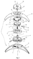
- the base part 1 of the device which is also the housing represents, in two parts with a base part 2, which is generally adapted to the shape of the shoe and can be attached to the athletic shoe, and an upper 30, which the appropriate cover of the clamping device forms.
- a base part 2 which is generally adapted to the shape of the shoe and can be attached to the athletic shoe, and an upper 30, which the appropriate cover of the clamping device forms.
- a cylindrical recess 3 for receiving a rope pulley 6, which by means of a cylindrical projection 8 rotatably mounted in a central bore 4 of the base part 2 is.
- On the two side flanks of the base part 2 are in the area of Mid-level grooves 5, 5 'for the rope 45, which in different axial heights cylindrical recess 3 open and in which the rope 45 when operating the device slides.
- the pulley 6, the outer diameter of which essentially corresponds to the diameter of the depression 3 has on the cylindrical outer surface two rope grooves 7,7 ', in which two ropes 45 are fixed at certain points on the circumference in a known manner.
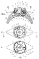
- the pulley 6 has one annular recess 10, the outer diameter of which is at least the diameter of the Rotating body 17 corresponds, since this, as can be seen in FIG. 2b, moves against the axial spring 16 penetrates into this recess 10.
- Internal toothing 14 has the intermediate ring 12 on the inside of a flat cylindrical Inner surface 12 ', the diameter of which is greater than or equal to the diameter of the Rotary body 17 is. There is also a on the outer circumference of the intermediate ring Tangentially lying recess 13 for mounting a tangential spring 15 through which the Intermediate ring 12 resiliently on a correspondingly arranged nose 35 of the base part 1 is supported.
- the locking piece 19 also be designed as a rotatably mounted pawl piece or as a self-resilient locking lug.
- the one shown in FIG Embodiment arranged on the inner surface teeth 14 optionally on the outside Intermediate ring 12, on / in the rotating body 17, or also be arranged on the base part 1, whereby the locking piece 19 is consequently mounted on the intermediate ring 12 or on the base part 1 in order to To be able to act internal teeth 14 according to the invention.
- the axially movable rotary body 17 also has a on the cylindrical outer surface Pawl teeth 21, which cooperates with a blockage 24, 27 so that a Rotation of the rotating body 17 and thus the rope pulley 6 in the pulling direction of the rope 45 is prevented.
- the rotating body On the side facing away from the pulley 6, the rotating body has a handle a pressure pin 22 which is connected to a rotary knob 38 which is rotatably mounted on the base part rotatably connected, but is axially displaceable with respect to the rotary knob 22.
- the blocking of the pawl teeth 21 consists of one or more spring-loaded locking lugs 27 arranged along a circle, which by means of axes 28 in Bores 33 of the base part 1 are rotatably mounted and have an open spring ring 24 in Are loaded in the direction of the pawl teeth 21, the spring ring 24 through an opening 25 is secured against rotation on a locking lug 34 of the base part 1.
- Locking lugs 27 can also be loaded with springs of a different type, or are designed to be self-resilient be.
- the second part of the housing is formed by the upper part 30, which is like the base part 2 has flanks on both sides, which cover the cable grooves 5, 5 '. Owns in the center the upper part 30 has an opening 37 through which the free end of the pressure pin 22 of the Rotating body 17 is guided out of the housing.
- the groove 32 is in the effective range Locking lugs broken in the radial direction inwards, so that the locking lugs 27 on the Pawl teeth 21 can attack, and has at one point between two locking lugs 27, a locking lug 34 through which the spring ring 24 is secured against rotation.
- the locking lugs 27 act are in the upper part 30 of the Base part 1 along a circle bores 33 are provided, in which the axes 28 of the Locking lugs are rotatably mounted.
- the upper part 30 has an annular projection 36, on which an Rotary knob 38 is rotatably mounted, which corresponds to the outer shape of the pressure pin 22 has a precisely fitting axial recess 39, whereby this pressure pin 22 with the Knob 38 is rotatably connected, but is axially displaceably mounted.
- the outer shape of the pressure pin and the exact fit Recess 39 is hexagonal.
- the rotary knob 38 also points in the area of this Recess 39 a funnel-shaped recess 41, which is easier axial actuation of the Pressure pin 22 allows, and on the outer circumference webs or grooves that a Ensure that the rotary knob turns non-slip.
- the pressure pin 22 can be operated with the rotary knob 38 be formed in one piece, the base part 1 along the central plane in the axial direction is divided and therefore no longer from the base or upper part but from two roughly mirrored side panels.
- the rotating body 17 When the rope 45 is tensioned, the rotating body 17 is initially shown in FIG. 2b in the starting position (A), in which the locking lugs 27 according to FIG. 3a in the Teeth 21 of the rotating body 17 are engaged.
- the rotating body 17 By turning the rotary knob 38 in The rotating body 17, which is connected to it in a rotationally fixed manner, rotates clockwise and also rotates with it non-rotatably connected rope pulley 6, whereby optionally one or two in grooves 5, 5 ' sliding ropes 45 are wound in corresponding grooves 7, 7 'of the pulley 6.
- the Locking lugs 27 are, while the rotating body 17 by one tooth each Internal gear 14 rotated further, rotated about the axis 28 and as shown in Fig.
- the intermediate ring 12 is by means of the tangential spring 15 so supported on the base part that this intermediate ring 12 by one certain angle is rotatable, the size of the angle of rotation of the tangential spring 15, or the cable is controlled so that these two sizes are in equilibrium stand.
- the clamping device when the rotary body 17 is in the central position B is brought, even before the relaxation mechanism 14 according to the invention comes into force, 19 somewhat relieved.
- a further relief of the cable pull will be as above described by successively moving the rotating body 17 from the starting position A in the middle position B is reached by pressing on the pressure pin 22.
Landscapes
- Footwear And Its Accessory, Manufacturing Method And Apparatuses (AREA)
- Pulleys (AREA)
Description
Claims (19)
- Spannvorrichtung für einen Sportschuh, insbesondere einen Schischuh, die einen an dem Sportschuh befestigbaren Basisteil (1) aufweist, in dem eine drehfest mit einem axial bewegbaren Drehkörper (17) verbundene Seilrolle (6) für ein Seil (45) angeordnet ist, wobei der eine Handhabe (22, 38) aufweisende Drehkörper in axialer Richtung mittels einer Axialfeder (16) belastet ist und durch die axiale Bewegbarkeit eine Ausgangsstellung (A) einnehmen kann, in der eine Verzahnung (21) am Drehkörper (17) mit einer Blockierung (24, 27) am Basisteil (1) zusammenwirkt, um eine Drehung gegen die Zugrichtung des Seiles (45) zu verhindern, und bei Druck auf die Handhabe (22, 38) gegen die Kraft der Axialfeder (16) eine Freilaufstellung (C) einnehmen kann, in der die Blockierung (24, 27) von der Verzahnung (21) gelöst ist und der Drehkörper (17) in beiden Richtungen frei drehbar ist, dadurch gekennzeichnet, daß ein am Basisteil (1) abgestützter Zwischenring (12) mit dem Drehkörper (17) über ein Sperrstück (19) und eine weitere Verzahnung (14), die aus n Segmenten mit jeweils in axialer Richtung wendelförmig ausgebildeten Gleitflanken (114', 214', ..., n14') und radial ausgebildeten Sperrflanken (114'', 214'', ..., n14'') besteht, so gekoppelt ist, daß durch axiales Bewegen des Drehkörpers (17) gegen die axiale Federkraft (16) in eine Mittelstellung (B) zwischen der Ausgangsstellung (A) und der Freilaufstellung (C) das federbelastete Sperrstück (19), das an einer Sperrflanke (114'') anliegt, zunächst gegen die axiale Federkratt (16) entlang dieser Sperrflanke und bei Vorliegen eines Seilzuges in der Folge bei gleichzeitiger Bewegung in Richtung der axialen Federkraft (16) sich entlang der Gleitflanke (114') bis zur nächsten Sperrflanke (214'') bewegt, wodurch sich der Drehkörper um einen bestimmten Winkel verdreht und axial wieder in die Ausgangsstellung (A) gelangt.
- Vorrichtung nach Anspruch 1, dadurch gekennzeichnet, daß der Basisteil (1) als zweiteiliges Gehäuse mit einem am Sportschuh befestigbaren Grundteil (2) und einem Oberteil (30) ausgebildet ist.
- Vorrichtung nach Anspruch 1 oder 2, dadurch gekennzeichnet, daß der Basisteil (1) zur Anpassung an die Form des Sportschuhes gekrümmt ist.
- Vorrichtung nach Anspruch 2 oder 3, dadurch gekennzeichnet, daß der Grundteil (2) des Basisteils (1) eine zylindrische Vertiefung (3) zur Aufnahme der Seilrolle (6) und eine Bohrung (4) zur drehbaren Lagerung eines zylindrischen Vorsprunges (8) der Seilrolle (6) aufweist.
- Vorrichtung nach einem der Ansprüche 2 bis 4, dadurch gekennzeichnet, daß der Grundteil (2) des Basisteils (1) eine Rille (5) für das Seil (45) aufweist, die in die zylindrische Ausnehmung (3) des Grundteils (2) mündet.
- Vorrichtung nach einem der Ansprüche 2 bis 4, dadurch gekennzeichnet, daß der Grundteil (2) des Basisteils (1) zu beiden Seiten der zylindrischen Vertiefung (3) Seilrillen (5, 5') aufweist, die in unterschiedlicher axialer Höhe in die Vertiefung (3) münden.
- Vorrichtung nach Anspruch 6, dadurch gekennzeichnet, daß die Seilrolle (6) zwei Rillen (7,7') zum Auf/Abwickeln zweier Seile (45) mit einer solchen axialen Lage aufweist, daß die Seile (45) in entsprechende Rillen (5,5') gleiten.
- Vorrichtung nach einem der Ansprüche 1 bis 7, dadurch gekennzeichnet, daß die Seilrolle (6) einen zentrischen Zapfen (9) zur formschlüssigen Verbindung mit einer Ausnehmung (23) des Drehkörpers (17) aufweist und dieser Zapfen (9) eine axiale Ausnehmung (11) zur Aufnahme der Axialfeder (16) aufweist, die zwischen dem Drehkörper (17) und der Seilrolle (6) wirkt.
- Vorrichtung nach einem der Ansprüche 1 bis 8, dadurch gekennzeichnet, daß die Seilrolle (6) an der dem Drehkörper (17) zugewandten Seite eine ringförmige Ausnehmung (10) aufweist, deren Außendurchmesser größer oder gleich dem Durchmesser des Drehkörpers (17) ist.
- Vorrichtung nach einem der Ansprüche 1 bis 9, dadurch gekennzeichnet, daß die Verzahnung (14) an der Innenfläche des Zwischenringes (12) und das Sperrstück (19) seitlich am Drehkörper (17) angeordnet ist.
- Vorrichtung nach Anspruch 10, dadurch gekennzeichnet, daß der Drehkörper (17) eine seitliche Ausnehmung (20) zur Aufnahme einer das Sperrstück (19) belastenden Feder (18) und zur teilweisen Aufnahme des Sperrstückes (19) aufweist.
- Vorrichtung nach einem der Ansprüche 1 bis 11, dadurch gekennzeichnet, daß das Sperrstück (19) als Sitz für die das Sperrstück belastende Feder (18) einen zylindrischen Zapfen (19') aufweist.
- Vorrichtung nach einem der Ansprüche 1 bis 12, dadurch gekennzeichnet, daß das Sperrstück (19) an der dem Federsitz (19') abgewandten Seite abgeschrägt ein der Verzahnung (14) angepaßtes, abgeschrägtes Ende (19'') aufweist.
- Vorrichtung nach einem der Ansprüche 1 bis 13, dadurch gekennzeichnet, daß der Zwischenring (12) bezüglich des Basisteils (1) gegen eine tangentiale Federkraft (15) um einen bestimmten Winkel verdrehbar ist.
- Vorrichtung nach Anspruch 14, dadurch gekennzeichnet, daß der Zwischenring (12) eine tangentiale Ausnehmung (13) aufweist, die zur Lagerung der tangentialen Federkraft (15) einer Nase (35) des Basisteils (1) zugeordnet ist.
- Vorrichtung nach einem der Ansprüche 1 bis 15, dadurch gekennzeichnet, daß der Drehkörper (17) eine entlang des Umfangs angeordnete Klinkenverzahnung (21) aufweist, die in der Ausgangsstellung (A) des Drehkörpers (17) mit einer oder mehreren, entlang eines Kreises angeordneten Sperrnasen (27) gegen ein Verdrehen des Drehkörpers (17) in Zugrichtung des Seiles (45) gesichert ist, wobei die Sperrnasen (27) mittels Achsen (28) in Bohrungen (33) des Basisteils (1) gelagert und durch einen offenen Federring (24), der durch eine Rastnase (34) des Basisteils (1) gegen Verdrehung gesichert ist, in Richtung Klinkenverzahnung (21) belastet sind.
- Vorrichtung nach einem der Ansprüche 1 bis 16, dadurch gekennzeichnet, daß der axial bewegbare Drehkörper (17) als Handhabe einen Druckzapfen (22) aufweist, der an seinem freien Ende mittels einer Ausnehmung (39) eines Drehknopfes (38) an diesem drehfest und axial verschieblich gelagert ist.
- Vorrichtung nach Anspruch 17, dadurch gekennzeichnet, daß der Drehknopf (38) im Bereich der Ausnehmung (39) an der Oberseite eine trichterförmige Vertiefung (41) zur leichteren Betätigung des Druckzapfens (22) aufweist.
- Vorrichtung nach einem der Ansprüche 17 oder 18, dadurch gekennzeichnet, daß der Drehknopf (38) an der Unterseite eine ringförmige Ausnehmung (42) aufweist, durch die der Drehknopf (38) an einem ringförmigen Vorsprung (36) des Oberteils (30) der Basis (1) drehbar gelagert ist.
Priority Applications (2)
| Application Number | Priority Date | Filing Date | Title |
|---|---|---|---|
| DE59309371T DE59309371D1 (de) | 1993-11-04 | 1993-11-04 | Spannvorrichtung für einen Sportschuh |
| EP19930890219 EP0651954B1 (de) | 1993-11-04 | 1993-11-04 | Spannvorrichtung für einen Sportschuh |
Applications Claiming Priority (1)
| Application Number | Priority Date | Filing Date | Title |
|---|---|---|---|
| EP19930890219 EP0651954B1 (de) | 1993-11-04 | 1993-11-04 | Spannvorrichtung für einen Sportschuh |
Publications (2)
| Publication Number | Publication Date |
|---|---|
| EP0651954A1 EP0651954A1 (de) | 1995-05-10 |
| EP0651954B1 true EP0651954B1 (de) | 1999-02-10 |
Family
ID=8215430
Family Applications (1)
| Application Number | Title | Priority Date | Filing Date |
|---|---|---|---|
| EP19930890219 Expired - Lifetime EP0651954B1 (de) | 1993-11-04 | 1993-11-04 | Spannvorrichtung für einen Sportschuh |
Country Status (2)
| Country | Link |
|---|---|
| EP (1) | EP0651954B1 (de) |
| DE (1) | DE59309371D1 (de) |
Cited By (23)
| Publication number | Priority date | Publication date | Assignee | Title |
|---|---|---|---|---|
| WO2005013748A1 (de) | 2003-08-04 | 2005-02-17 | Japana Co., Ltd. | Spannvorrichtung für zugkabel, insbesondere von zugkabel-schnürungen an schuhen |
| US8858482B2 (en) | 2008-05-15 | 2014-10-14 | Ossur Hf | Orthopedic devices utilizing rotary tensioning |
| US8939925B2 (en) | 2010-02-26 | 2015-01-27 | Ossur Hf | Tightening system for an orthopedic article |
| US9314363B2 (en) | 2013-01-24 | 2016-04-19 | Ossur Hf | Orthopedic device for treating complications of the hip |
| US9370440B2 (en) | 2012-01-13 | 2016-06-21 | Ossur Hf | Spinal orthosis |
| US9414953B2 (en) | 2009-02-26 | 2016-08-16 | Ossur Hf | Orthopedic device for treatment of the back |
| US9439800B2 (en) | 2009-01-14 | 2016-09-13 | Ossur Hf | Orthopedic device, use of orthopedic device and method for producing same |
| US9468554B2 (en) | 2013-01-24 | 2016-10-18 | Ossur Iceland Ehf | Orthopedic device for treating complications of the hip |
| US9572705B2 (en) | 2012-01-13 | 2017-02-21 | Ossur Hf | Spinal orthosis |
| US9597219B2 (en) | 2009-11-04 | 2017-03-21 | Ossur Hf | Thoracic lumbar sacral orthosis |
| US9763808B2 (en) | 2014-05-19 | 2017-09-19 | Ossur Hf | Adjustable prosthetic device |
| US9795500B2 (en) | 2013-01-24 | 2017-10-24 | Ossur Hf | Orthopedic device for treating complications of the hip |
| US9872794B2 (en) | 2012-09-19 | 2018-01-23 | Ossur Hf | Panel attachment and circumference adjustment systems for an orthopedic device |
| US10159592B2 (en) | 2015-02-27 | 2018-12-25 | Ossur Iceland Ehf | Spinal orthosis, kit and method for using the same |
| US10182935B2 (en) | 2014-10-01 | 2019-01-22 | Ossur Hf | Support for articles and methods for using the same |
| CN110049694A (zh) * | 2016-12-09 | 2019-07-23 | Boa科技股份有限公司 | 基于卷轴的闭合系统 |
| CN110072403A (zh) * | 2016-08-30 | 2019-07-30 | 帕尔瓦伊姆机构公司 | 系带操作装置 |
| US10512305B2 (en) | 2014-07-11 | 2019-12-24 | Ossur Hf | Tightening system with a tension control mechanism |
| US10561520B2 (en) | 2015-02-27 | 2020-02-18 | Ossur Iceland Ehf | Spinal orthosis, kit and method for using the same |
| KR20210045583A (ko) * | 2019-10-17 | 2021-04-27 | 주식회사 프리락 글로벌 | 모자용 와이어 조임 장치 |
| US11000439B2 (en) | 2017-09-28 | 2021-05-11 | Ossur Iceland Ehf | Body interface |
| US11246734B2 (en) | 2017-09-07 | 2022-02-15 | Ossur Iceland Ehf | Thoracic lumbar sacral orthosis attachment |
| US12295460B2 (en) | 2011-10-13 | 2025-05-13 | Boa Technology, Inc. | Reel-based lacing system |
Families Citing this family (52)
| Publication number | Priority date | Publication date | Assignee | Title |
|---|---|---|---|---|
| DE29701491U1 (de) * | 1997-01-30 | 1998-05-28 | Puma Ag Rudolf Dassler Sport, 91074 Herzogenaurach | Drehverschluß für einen Schuh |
| US20060156517A1 (en) | 1997-08-22 | 2006-07-20 | Hammerslag Gary R | Reel based closure system |
| US20080060167A1 (en) | 1997-08-22 | 2008-03-13 | Hammerslag Gary R | Reel based closure system |
| DE19945045A1 (de) * | 1999-09-20 | 2001-03-22 | Burkhart Unternehmensberatung | Verschluss-System |
| WO2006050266A2 (en) | 2004-10-29 | 2006-05-11 | Boa Technology, Inc. | Reel based closure system |
| EP2076224B1 (de) | 2006-09-12 | 2016-08-24 | Boa Technology, Inc. | Verschlusssystem für gurte, schutzkleidung und ähnliche artikel |
| JP5709526B2 (ja) | 2008-01-18 | 2015-04-30 | ボア テクノロジー,インコーポレイテッド | 閉塞システム |
| EP2378911B1 (de) * | 2008-11-21 | 2014-05-21 | Boa Technology, Inc. | Schnürverschluss auf spulengrundlage |
| DE112011100318B4 (de) | 2010-01-21 | 2023-04-20 | Boa Technology, Inc. | Führungen für Schnürsysteme |
| CN102188079B (zh) * | 2010-03-16 | 2012-10-31 | 陈金柱 | 可调整带体松紧的无段式微调扣具 |
| US9375053B2 (en) | 2012-03-15 | 2016-06-28 | Boa Technology, Inc. | Tightening mechanisms and applications including the same |
| KR102566159B1 (ko) | 2010-04-30 | 2023-08-16 | 보아 테크놀러지, 인크. | 릴 기반 끈 조임 시스템 |
| US10070695B2 (en) | 2010-04-30 | 2018-09-11 | Boa Technology Inc. | Tightening mechanisms and applications including the same |
| US9918865B2 (en) | 2010-07-01 | 2018-03-20 | 3M Innovative Properties Company | Braces using lacing systems |
| KR20130103705A (ko) | 2010-07-01 | 2013-09-24 | 보아 테크놀러지, 인크. | 끈 가이드 |
| ITPD20120016A1 (it) * | 2012-01-19 | 2013-07-20 | Sidi Sport S R L | Dispositivo di chiusura a rilascio controllato per calzature. |
| US9179729B2 (en) | 2012-03-13 | 2015-11-10 | Boa Technology, Inc. | Tightening systems |
| DE112013005273B4 (de) | 2012-11-02 | 2017-08-24 | Boa Technology, Inc. | Kupplungsteile für Verschlussvorrichtungen und -systeme |
| WO2014074645A2 (en) | 2012-11-06 | 2014-05-15 | Boa Technology Inc. | Devices and methods for adjusting the fit of footwear |
| US9554935B2 (en) | 2013-01-24 | 2017-01-31 | Ossur Hf | Orthopedic device for treating complications of the hip |
| EP3607845B1 (de) | 2013-01-28 | 2022-11-09 | Boa Technology Inc. | Riemenfixieranordnung und system |
| US10702409B2 (en) | 2013-02-05 | 2020-07-07 | Boa Technology Inc. | Closure devices for medical devices and methods |
| US10251451B2 (en) | 2013-03-05 | 2019-04-09 | Boa Technology Inc. | Closure devices including incremental release mechanisms and methods therefor |
| EP2964048B1 (de) | 2013-03-05 | 2019-08-28 | Boa Technology Inc. | Systeme und vorrichtungen zum automatischen schliessen von medizinischen vorrichtungen |
| WO2014165541A2 (en) | 2013-04-01 | 2014-10-09 | Boa Technology Inc. | Methods and devices for retrofitting footwear to include a reel based closure system |
| ITTV20130045A1 (it) * | 2013-04-09 | 2014-10-10 | Northwave Srl | Dispositivo di serraggio |
| US10076160B2 (en) | 2013-06-05 | 2018-09-18 | Boa Technology Inc. | Integrated closure device components and methods |
| FI12797Y1 (en) | 2013-06-05 | 2020-10-16 | Boa Tech Inc | Roller-based closure device for tightening an object |
| JP6105404B2 (ja) | 2013-06-18 | 2017-03-29 | 株式会社ジャパーナ | 靴紐巻取用リール |
| JP6087219B2 (ja) | 2013-06-18 | 2017-03-01 | 株式会社ジャパーナ | 靴紐巻取装置 |
| WO2015003079A1 (en) | 2013-07-02 | 2015-01-08 | Boa Technology Inc. | Tension limiting mechanisms for closure devices and methods therefor |
| WO2015006616A1 (en) * | 2013-07-10 | 2015-01-15 | Boa Technology Inc. | Closure devices including incremental release mechanisms and methods therefor |
| EP3593766B1 (de) * | 2013-07-30 | 2024-07-10 | United Surgical Associates, Inc. | System zum sichern und spannen einer orthopädischen stütze |
| WO2015035257A2 (en) | 2013-09-05 | 2015-03-12 | Boa Technology Inc. | Alternative lacing guides for tightening mechanisms and methods therefor |
| CN203492894U (zh) * | 2013-09-11 | 2014-03-26 | 陈金柱 | 带体收放装置 |
| KR102297325B1 (ko) | 2013-09-13 | 2021-09-03 | 보아 테크놀러지, 인크. | 릴 기반 폐쇄 장치 및 그에 따른 방법 |
| KR101895140B1 (ko) | 2013-11-18 | 2018-09-04 | 보아 테크놀러지, 인크. | 보철 및 장구의 자동 폐쇄를 제공하기 위한 방법 및 장치 |
| USD835976S1 (en) | 2014-01-16 | 2018-12-18 | Boa Technology Inc. | Coupling member |
| US20160058127A1 (en) | 2014-08-28 | 2016-03-03 | Boa Technology Inc. | Devices and methods for enhancing the fit of boots and other footwear |
| WO2016057697A1 (en) | 2014-10-07 | 2016-04-14 | Boa Technology Inc. | A tension adjustment mechanism and a method for adjusting the fit of a shoe |
| USD835898S1 (en) | 2015-01-16 | 2018-12-18 | Boa Technology Inc. | Footwear lace tightening reel stabilizer |
| EP3182941B1 (de) * | 2015-02-27 | 2018-03-14 | F.G.P. S.R.L. | Manuell betätigte drehverriegelungsvorrichtung für orthopädische orthesen oder stützen |
| US10004297B2 (en) | 2015-10-15 | 2018-06-26 | Boa Technology Inc. | Lacing configurations for footwear |
| CN106919220B (zh) * | 2015-12-25 | 2018-06-05 | 陈金柱 | 紧固装置 |
| US10499709B2 (en) | 2016-08-02 | 2019-12-10 | Boa Technology Inc. | Tension member guides of a lacing system |
| US10543630B2 (en) | 2017-02-27 | 2020-01-28 | Boa Technology Inc. | Reel based closure system employing a friction based tension mechanism |
| US11357279B2 (en) | 2017-05-09 | 2022-06-14 | Boa Technology Inc. | Closure components for a helmet layer and methods for installing same |
| US12396520B2 (en) | 2017-07-18 | 2025-08-26 | Boa Technology Inc. | Configurations for footwear employing reel based closure systems |
| US10772384B2 (en) | 2017-07-18 | 2020-09-15 | Boa Technology Inc. | System and methods for minimizing dynamic lace movement |
| WO2020160421A1 (en) | 2019-02-01 | 2020-08-06 | Boa Technology Inc. | Reel based closure devices for tightening a ski boot |
| CN118907988A (zh) | 2019-05-01 | 2024-11-08 | Boa科技股份有限公司 | 基于卷轴的闭合系统 |
| DE202020100438U1 (de) * | 2020-01-28 | 2021-04-29 | Sudhaus Gmbh | Schloss und Behälter mit einem solchen Schloss |
Family Cites Families (3)
| Publication number | Priority date | Publication date | Assignee | Title |
|---|---|---|---|---|
| IT1220010B (it) * | 1987-07-03 | 1990-06-06 | Nordica Spa | Dispositivo di serraggio e regolazione particolarmente per scarponi da sci |
| AT392334B (de) * | 1988-08-08 | 1991-03-11 | Dynafit Gmbh | Wickelvorrichtung fuer seilzuege, insbesondere fuer skischuhe |
| DE9200982U1 (de) * | 1992-01-28 | 1993-05-27 | PUMA AG Rudolf Dassler Sport, 8522 Herzogenaurach | Schuh mit einem Zentralverschluß |
-
1993
- 1993-11-04 DE DE59309371T patent/DE59309371D1/de not_active Expired - Fee Related
- 1993-11-04 EP EP19930890219 patent/EP0651954B1/de not_active Expired - Lifetime
Cited By (46)
| Publication number | Priority date | Publication date | Assignee | Title |
|---|---|---|---|---|
| WO2005013748A1 (de) | 2003-08-04 | 2005-02-17 | Japana Co., Ltd. | Spannvorrichtung für zugkabel, insbesondere von zugkabel-schnürungen an schuhen |
| US10492940B2 (en) | 2008-05-15 | 2019-12-03 | Ossur Hf | Orthopedic devices utilizing rotary tensioning |
| US8858482B2 (en) | 2008-05-15 | 2014-10-14 | Ossur Hf | Orthopedic devices utilizing rotary tensioning |
| US9439800B2 (en) | 2009-01-14 | 2016-09-13 | Ossur Hf | Orthopedic device, use of orthopedic device and method for producing same |
| US10828186B2 (en) | 2009-02-26 | 2020-11-10 | Ossur Hf | Orthopedic device for treatment of the back |
| US9414953B2 (en) | 2009-02-26 | 2016-08-16 | Ossur Hf | Orthopedic device for treatment of the back |
| US12127965B2 (en) | 2009-02-26 | 2024-10-29 | Ossur Hf | Orthopedic device for treatment of the back |
| US9597219B2 (en) | 2009-11-04 | 2017-03-21 | Ossur Hf | Thoracic lumbar sacral orthosis |
| US10617552B2 (en) | 2009-11-04 | 2020-04-14 | Ossur Hf | Thoracic lumbar sacral orthosis |
| US8939925B2 (en) | 2010-02-26 | 2015-01-27 | Ossur Hf | Tightening system for an orthopedic article |
| US10264835B2 (en) | 2010-02-26 | 2019-04-23 | Ossur Hf | Tightening system for an orthopedic article |
| US12295460B2 (en) | 2011-10-13 | 2025-05-13 | Boa Technology, Inc. | Reel-based lacing system |
| US9370440B2 (en) | 2012-01-13 | 2016-06-21 | Ossur Hf | Spinal orthosis |
| US9572705B2 (en) | 2012-01-13 | 2017-02-21 | Ossur Hf | Spinal orthosis |
| US10898365B2 (en) | 2012-01-13 | 2021-01-26 | Ossur Hf | Spinal orthosis |
| US12186226B2 (en) | 2012-01-13 | 2025-01-07 | Ossur Hf | Spinal orthosis |
| US10980657B2 (en) | 2012-09-19 | 2021-04-20 | Ossur Hf | Panel attachment and circumference adjustment systems for an orthopedic device |
| US9872794B2 (en) | 2012-09-19 | 2018-01-23 | Ossur Hf | Panel attachment and circumference adjustment systems for an orthopedic device |
| US11484428B2 (en) | 2012-09-19 | 2022-11-01 | Ossur Hf | Panel attachment and circumference adjustment systems for an orthopedic device |
| US9795500B2 (en) | 2013-01-24 | 2017-10-24 | Ossur Hf | Orthopedic device for treating complications of the hip |
| US9468554B2 (en) | 2013-01-24 | 2016-10-18 | Ossur Iceland Ehf | Orthopedic device for treating complications of the hip |
| US9314363B2 (en) | 2013-01-24 | 2016-04-19 | Ossur Hf | Orthopedic device for treating complications of the hip |
| US10357391B2 (en) | 2013-01-24 | 2019-07-23 | Ossur Hf | Orthopedic device for treating complications of the hip |
| US11259948B2 (en) | 2013-01-24 | 2022-03-01 | Ossur Hf | Orthopedic device for treating complications of the hip |
| US9393144B2 (en) | 2013-01-24 | 2016-07-19 | Ossur Hf | Orthopedic device for treating complications of the hip |
| US12433778B2 (en) | 2013-01-24 | 2025-10-07 | Ossur Hf | Orthopedic device for treating complications of the hip |
| US9987158B2 (en) | 2013-01-24 | 2018-06-05 | Ossur Hf | Orthopedic device for treating complications of the hip |
| US9763808B2 (en) | 2014-05-19 | 2017-09-19 | Ossur Hf | Adjustable prosthetic device |
| US10512305B2 (en) | 2014-07-11 | 2019-12-24 | Ossur Hf | Tightening system with a tension control mechanism |
| US11304838B2 (en) | 2014-10-01 | 2022-04-19 | Ossur Hf | Support for articles and methods for using the same |
| US10182935B2 (en) | 2014-10-01 | 2019-01-22 | Ossur Hf | Support for articles and methods for using the same |
| US12251327B2 (en) | 2014-10-01 | 2025-03-18 | Ossur Hr | Support for articles and methods for using the same |
| US11571323B2 (en) | 2015-02-27 | 2023-02-07 | Ossur Iceland Ehf | Spinal orthosis, kit and method for using the same |
| US10159592B2 (en) | 2015-02-27 | 2018-12-25 | Ossur Iceland Ehf | Spinal orthosis, kit and method for using the same |
| US10561520B2 (en) | 2015-02-27 | 2020-02-18 | Ossur Iceland Ehf | Spinal orthosis, kit and method for using the same |
| US11273064B2 (en) | 2015-02-27 | 2022-03-15 | Ossur Iceland Ehf | Spinal orthosis, kit and method for using the same |
| CN110072403A (zh) * | 2016-08-30 | 2019-07-30 | 帕尔瓦伊姆机构公司 | 系带操作装置 |
| CN110072403B (zh) * | 2016-08-30 | 2021-06-25 | 帕尔瓦伊姆机构公司 | 系带操作装置 |
| CN110049694A (zh) * | 2016-12-09 | 2019-07-23 | Boa科技股份有限公司 | 基于卷轴的闭合系统 |
| US11419389B2 (en) | 2016-12-09 | 2022-08-23 | Boa Technology Inc. | Reel based closure system |
| US12090079B2 (en) | 2017-09-07 | 2024-09-17 | Ossur Iceland Ehf | Thoracic lumbar sacral orthosis attachment |
| US11684506B2 (en) | 2017-09-07 | 2023-06-27 | Ossur Iceland Ehf | Thoracic lumbar sacral orthosis attachment |
| US11246734B2 (en) | 2017-09-07 | 2022-02-15 | Ossur Iceland Ehf | Thoracic lumbar sacral orthosis attachment |
| US11850206B2 (en) | 2017-09-28 | 2023-12-26 | Ossur Iceland Ehf | Body interface |
| US11000439B2 (en) | 2017-09-28 | 2021-05-11 | Ossur Iceland Ehf | Body interface |
| KR20210045583A (ko) * | 2019-10-17 | 2021-04-27 | 주식회사 프리락 글로벌 | 모자용 와이어 조임 장치 |
Also Published As
| Publication number | Publication date |
|---|---|
| EP0651954A1 (de) | 1995-05-10 |
| DE59309371D1 (de) | 1999-03-25 |
Similar Documents
| Publication | Publication Date | Title |
|---|---|---|
| EP0651954B1 (de) | Spannvorrichtung für einen Sportschuh | |
| DE102012208542B4 (de) | Vorrichtung zum Binden eines Schnürsenkels | |
| EP0255869B1 (de) | Drehverschluss für einen Sportschuh, insbesondere Skischuh | |
| EP0697826B1 (de) | Schuhverschluss | |
| EP0393380B1 (de) | Drehverschluss für einen Sportschuh | |
| EP0615705B1 (de) | Drehverschluss | |
| EP0412290B1 (de) | Drehverschluss für einen Sportschuh, insbesondere einen Skischuh | |
| DE69511950T2 (de) | Entkuppelbares selbstblockierendes Abseilgerät | |
| DE2717157C2 (de) | Gurt- bzw. Seil-Ratsche | |
| DE3781565T2 (de) | Vorrichtung zum schliessen der oberteile von schischuhen. | |
| DE3203750A1 (de) | Spannschloss fuer gurtbaender | |
| DE2943976A1 (de) | Spannhebelverschluss fuer schuhe, insbesondere skistiefel | |
| EP4041018B1 (de) | Drehverschluss mit spannelement | |
| DE2852871C2 (de) | ||
| DE2504576B2 (de) | Selbsttätig sperrende Aufwickelvorrichtung für einen Sicherheitsgurt | |
| DE3323150C2 (de) | ||
| DE4307948A1 (de) | ||
| DE1905819U (de) | Mit ausklappbarer handkurbel zu betaetigende trommel zum auf- und abwickeln, vorzugsweise von messbaendern. | |
| DE102014108902B4 (de) | Spannschloss für eine Gleitschutzkette | |
| EP0352873A2 (de) | Gleitschutzvorrichtung für Fahrzeugräder | |
| AT398158B (de) | Spannvorrichtung | |
| EP0920889B1 (de) | Willkürlich schliess- und lösbare Verbindungseinrichtung | |
| DE4004244A1 (de) | Angelrolle mit spule und einstellbarer bremse | |
| DE3315928C2 (de) | Traggehäuse für Tiergurtleinen | |
| DE2155543A1 (de) | Schlitzverschluß |
Legal Events
| Date | Code | Title | Description |
|---|---|---|---|
| PUAI | Public reference made under article 153(3) epc to a published international application that has entered the european phase |
Free format text: ORIGINAL CODE: 0009012 |
|
| AK | Designated contracting states |
Kind code of ref document: A1 Designated state(s): CH DE FR IT LI SE |
|
| 17P | Request for examination filed |
Effective date: 19951103 |
|
| 17Q | First examination report despatched |
Effective date: 19970708 |
|
| GRAG | Despatch of communication of intention to grant |
Free format text: ORIGINAL CODE: EPIDOS AGRA |
|
| RAP1 | Party data changed (applicant data changed or rights of an application transferred) |
Owner name: AM S.R.L. |
|
| GRAG | Despatch of communication of intention to grant |
Free format text: ORIGINAL CODE: EPIDOS AGRA |
|
| GRAH | Despatch of communication of intention to grant a patent |
Free format text: ORIGINAL CODE: EPIDOS IGRA |
|
| GRAH | Despatch of communication of intention to grant a patent |
Free format text: ORIGINAL CODE: EPIDOS IGRA |
|
| GRAA | (expected) grant |
Free format text: ORIGINAL CODE: 0009210 |
|
| AK | Designated contracting states |
Kind code of ref document: B1 Designated state(s): CH DE FR IT LI SE |
|
| REG | Reference to a national code |
Ref country code: CH Ref legal event code: EP |
|
| REF | Corresponds to: |
Ref document number: 59309371 Country of ref document: DE Date of ref document: 19990325 |
|
| ITF | It: translation for a ep patent filed | ||
| REG | Reference to a national code |
Ref country code: CH Ref legal event code: NV Representative=s name: ABREMA AGENCE BREVETS ET MARQUES GANGUILLET & HUMP |
|
| ET | Fr: translation filed | ||
| PG25 | Lapsed in a contracting state [announced via postgrant information from national office to epo] |
Ref country code: SE Free format text: LAPSE BECAUSE OF NON-PAYMENT OF DUE FEES Effective date: 19991105 |
|
| PG25 | Lapsed in a contracting state [announced via postgrant information from national office to epo] |
Ref country code: LI Free format text: LAPSE BECAUSE OF NON-PAYMENT OF DUE FEES Effective date: 19991130 Ref country code: CH Free format text: LAPSE BECAUSE OF NON-PAYMENT OF DUE FEES Effective date: 19991130 |
|
| PLBE | No opposition filed within time limit |
Free format text: ORIGINAL CODE: 0009261 |
|
| STAA | Information on the status of an ep patent application or granted ep patent |
Free format text: STATUS: NO OPPOSITION FILED WITHIN TIME LIMIT |
|
| 26N | No opposition filed | ||
| REG | Reference to a national code |
Ref country code: CH Ref legal event code: PL |
|
| EUG | Se: european patent has lapsed |
Ref document number: 93890219.4 |
|
| PG25 | Lapsed in a contracting state [announced via postgrant information from national office to epo] |
Ref country code: FR Free format text: LAPSE BECAUSE OF NON-PAYMENT OF DUE FEES Effective date: 20000731 |
|
| PG25 | Lapsed in a contracting state [announced via postgrant information from national office to epo] |
Ref country code: DE Free format text: LAPSE BECAUSE OF NON-PAYMENT OF DUE FEES Effective date: 20000901 |
|
| REG | Reference to a national code |
Ref country code: FR Ref legal event code: ST |
|
| PG25 | Lapsed in a contracting state [announced via postgrant information from national office to epo] |
Ref country code: IT Free format text: LAPSE BECAUSE OF NON-PAYMENT OF DUE FEES;WARNING: LAPSES OF ITALIAN PATENTS WITH EFFECTIVE DATE BEFORE 2007 MAY HAVE OCCURRED AT ANY TIME BEFORE 2007. THE CORRECT EFFECTIVE DATE MAY BE DIFFERENT FROM THE ONE RECORDED. Effective date: 20051104 |