EP0651966B2 - Vorrichtung zur Aufnahme und Halterung von runden und eckigen Gegenständen - Google Patents
Vorrichtung zur Aufnahme und Halterung von runden und eckigen Gegenständen Download PDFInfo
- Publication number
- EP0651966B2 EP0651966B2 EP94117346A EP94117346A EP0651966B2 EP 0651966 B2 EP0651966 B2 EP 0651966B2 EP 94117346 A EP94117346 A EP 94117346A EP 94117346 A EP94117346 A EP 94117346A EP 0651966 B2 EP0651966 B2 EP 0651966B2
- Authority
- EP
- European Patent Office
- Prior art keywords
- clamping jaws
- holder
- guide
- jaws
- slot
- Prior art date
- Legal status (The legal status is an assumption and is not a legal conclusion. Google has not performed a legal analysis and makes no representation as to the accuracy of the status listed.)
- Expired - Lifetime
Links
- 230000007704 transition Effects 0.000 claims description 6
- 210000000078 claw Anatomy 0.000 claims description 4
- 230000037431 insertion Effects 0.000 claims description 3
- 238000003780 insertion Methods 0.000 claims description 3
- 238000010073 coating (rubber) Methods 0.000 claims description 2
- 230000035515 penetration Effects 0.000 claims 2
- 230000013011 mating Effects 0.000 claims 1
- 230000000284 resting effect Effects 0.000 claims 1
- 230000036316 preload Effects 0.000 description 3
- 238000006073 displacement reaction Methods 0.000 description 2
- 238000011109 contamination Methods 0.000 description 1
- 230000002354 daily effect Effects 0.000 description 1
- 230000003203 everyday effect Effects 0.000 description 1
- 239000004744 fabric Substances 0.000 description 1
- 230000005484 gravity Effects 0.000 description 1
- 239000007788 liquid Substances 0.000 description 1
- 230000002093 peripheral effect Effects 0.000 description 1
- 239000004033 plastic Substances 0.000 description 1
- 238000007788 roughening Methods 0.000 description 1
- 239000000126 substance Substances 0.000 description 1
Images




Classifications
-
- B—PERFORMING OPERATIONS; TRANSPORTING
- B43—WRITING OR DRAWING IMPLEMENTS; BUREAU ACCESSORIES
- B43M—BUREAU ACCESSORIES NOT OTHERWISE PROVIDED FOR
- B43M99/00—Subject matter not provided for in other groups of this subclass
-
- A—HUMAN NECESSITIES
- A47—FURNITURE; DOMESTIC ARTICLES OR APPLIANCES; COFFEE MILLS; SPICE MILLS; SUCTION CLEANERS IN GENERAL
- A47L—DOMESTIC WASHING OR CLEANING; SUCTION CLEANERS IN GENERAL
- A47L13/00—Implements for cleaning floors, carpets, furniture, walls, or wall coverings
- A47L13/10—Scrubbing; Scouring; Cleaning; Polishing
- A47L13/50—Auxiliary implements
- A47L13/51—Storing of cleaning tools, e.g. containers therefor
- A47L13/512—Clamping devices for hanging the tools
-
- B—PERFORMING OPERATIONS; TRANSPORTING
- B25—HAND TOOLS; PORTABLE POWER-DRIVEN TOOLS; MANIPULATORS
- B25H—WORKSHOP EQUIPMENT, e.g. FOR MARKING-OUT WORK; STORAGE MEANS FOR WORKSHOPS
- B25H3/00—Storage means or arrangements for workshops facilitating access to, or handling of, work tools or instruments
- B25H3/04—Racks
Definitions
- the invention relates to a device for receiving and holding round or angular objects, especially for objects with a dimension of 0.5 up to 15 mm and a relatively low weight, with at least two opposing Jaws, which are arranged on a support body and by which at least one has at least one guide base that is in a guide of the carrier body is guided displaceably and by a spring force in an initial position is traceable and the surface of the clamping jaws facing the carrier body rests smoothly and flat and with the jaws facing each other Have inner surfaces.
- Pens consist of loops or holes in a carrier body but all the fundamental disadvantage that the brackets usually only for one certain size or a certain diameter of the object is provided are and in the case of deviations from this predetermined size, the fit more is given or the object comes to rest loosely in the holder. On Another problem arises from inaccurate guidance and poor hold in the bracket if the item is not the right size.
- the holding device consists of two Clamping brackets, which are rotatably attached to a support body and by a The spring can be compressed so that the object to be picked up is safe is held.
- the two clamps have one circular opening with a forward opening for insertion of the item. Due to the fixed diameter of the opening however, there is only the possibility to pick up objects of the same size. Smaller objects find no hold in the existing breakthrough and can thus not be included while much larger items are not in the opening of the two clamps can be inserted.
- a generic device is also known from US Pat. No. 5,554,380, which is designed as a cup holder and for fixing the to be picked up Object is provided in one level.
- the disadvantage of this version is from that the spring elements standing vertically on the support body are light are bendable and tiltable so that good guidance on the support body is not is guaranteed.
- US Pat. No. 670,446 describes a clamping device for items of jewelry, for example known, the two opposing jaws on a guide plate having.
- the jaws slide directly over a dovetail guide on the guide plate and are moved towards each other by spring force.
- the jaws are included with the items of jewelry, for example covered with a cloth and placed the objects between the flat surfaces. As far as the jaws lie against each other, the jewelry can only by manually pulling the jaws apart.
- the object of the invention is therefore to create a device with which objects of use or consumption of different sizes are easy to hold and easy to remove.
- the guide base is provided to achieve the object engages behind the support body at least partially and the jaws on their facing inner surfaces a shaped area and the direction of movement of the object have a bevel, in the transition area a narrowing between the bevel and the shaped area is trained.
- the Holding force can be selected depending on the spring preload so that the Objects are held in all positions in such a way that they both against the Gravity, as well as against vibrations in the position assigned to them remain without the objects being deformed or damaged.
- This Invention thus saves z.
- the jaws two opposite and have mirror-inverted inner surfaces that face the direction of movement of the object have a bevel and in the middle area are round or elliptical, with the transition area between the Bevel and the shaped area is formed a constriction.
- bevelling facilitates the feeding and introduction of the Objects while the narrowing slightly pushing the jaws apart makes it necessary for the introduction, so that after the merger of the Jaws the round or elliptically shaped area around which the object lies comes and prevents slipping out.
- the assembled Clamping jaws preferably three or four, a circular one in the center Have breakthrough
- the inner surface of the three jaws in cross section seen is circular and towards the direction of movement of the object bevelled and additionally round or elliptical in the middle Insert direction are formed and in the transition area between the Bevel and the formed area is also a constriction, so that the item is inserted through the three jaws and is secure can be held.
- the clamping jaws can be opened the inside surface has corrugation, roughening or rubber coating.
- two clamping jaws are present that face each other or three jaws around each 120 degrees or four jaws offset by 90 degrees to each other are, the clamping jaws each in at least one guide, for example one Groove or a slot are slidably mounted independently.
- the device is preferably equipped with two clamping jaws, which face one another face each other and in a rest position at least in the lower area touch so that the clamping jaws in the upper insertion area have a small gap form to facilitate the introduction of the object.
- three or four Clamping jaws can be arranged in a star shape, which is also in a rest position partially touch at least in the lower area so that it can be inserted is given perpendicular to the mounting plane of the device.
- the leadership of the The jaws consist of at least one guide base on the jaws and a groove or a slot in the carrier body, for example a carrier plate, so that the jaws can easily slide back and forth in the guide. By choosing a suitable plastic, the glide can be increased become.
- the groove or the slot is continuous to hold two jaws or split to hold one each Clamp is provided.
- two or more grooves or Slots are arranged parallel or at an angle to each other, preferably star-shaped or that two eccentric grooves or slots are provided, the grooves or the slots are arranged symmetrically around the center of the carrier body and equidistant are removed from the center of the support body.
- the clamping jaws cannot slip out of the carrier body provided that the guide base of the jaws at least two opposite aligned claws that engage behind the groove or slot, sliding shoes or has a triangular or dovetail guide and that the groove or the Slot has a corresponding receiving surface.
- the guide base below the groove or slot Rectangular, integrally formed console which at the bottom of the Slit of the support body rests or that the guide base below the groove or the slot has a crossbar which is integral with the guide base is integrally formed, the longitudinal extension of the crosspiece perpendicular to the groove or runs the slot and rests on the underside of the carrier body, whereby a Slipping out of the jaws from the slot is prevented and the thickness the brackets or the crossbar corresponds to approximately half the width of the slot.
- the guidance of the clamping jaws additionally from at least one hole in the brackets or the guide base the jaws and at least one bolt mounted in the carrier body exists, with the holes of the jaws in the middle or off-center in the direction of displacement the jaws are arranged and the bolt or bolts in at least two Support brackets or a support edge below the support body in the direction of displacement are arranged.
- the spring preload at least one spring is provided in the guide between the brackets or the guide base and a support bracket or the support edge of the carrier plate is arranged.
- Another Possibility to achieve the clamping force is that for the spring preload at least two springs are provided on the bolt (s) between the Consoles or the guide bases and the support brackets or the support edge of the Carrier body are arranged.
- the support body in the center a stop for the Has jaws so that the jaws have a larger opening distance to each other or that the support body in the center of a cylindrical or has conical opening for the insertable object, so that the Object can be inserted through the device.
- the carrier body is round is formed and rotated continuously or in locking stages on a base plate or a base body is attached, the carrier body on its underside has at least three retaining claws that drill a hole in the base plate or Reach behind the base body.
- the carrier body via a screw connection, clamp, or tongue and groove and similar Fasteners are held on the base plate.
- the carrier body by means of two intermeshing sprockets, of which one with the carrier body and one with the base plate or the base body is connected, is held in a certain rotational position and wherein the tooth engagement under spring tension and the engagement of the sprockets by pressing the carrier body can be lifted around the jaws together with the object to twist on the base plate or the base body.
- the carrier body Base plate includes with its edge and one or more semicircular Has locking lugs on the inside of the edge, which in a corresponding Engage the catch of the base plate, causing a rotation by a small Force is made possible.
- the carrier body or the Base plate is equipped with a rubber lip.
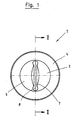
- Figure 1 shows a plan view of a first embodiment the device 1 in a closed representation and Figure 2 a Sectional view according to section line I-I of Figure 1.
- the device 1 has two centrally arranged Jaws 2, 3 on a support body in the form a support plate 4.
- the jaws 2, 3 are mutually arranged opposite and point in this first embodiment of the invention one in essential spherical cross section of a quarter ball on, wherein one of the side surfaces 5, 6 of the Clamping jaws 2, 3 to lie on the carrier plate 4 comes and slide back and forth on the carrier plate can.
- the two opposite inner surfaces 7, 8 of the jaws 2, 3 are perpendicular to the side surfaces 5, 6 arranged and are mirror images.
- the carrier plate 4 has a round shape that however, can be changed as desired, as it is in the Invention not on the outer shape of the support body 4 arrives, so that a round, triangular, square or other type of carrier into consideration can be pulled.
- the clamping jaws 2, 3 have on their lower surface 5, 6 one essentially rectangular guide base 15, 16 on the in a groove or slot 17 of the support plate is guided, the slot continuously or can be made in two parts. Furthermore located a console on each of the guide bases 15, 16 18, 19, for example the slot 17 of the carrier plate 4 reaches behind to form a kind of sliding shoe and slipping or falling out of the jaws 2, 3 to prevent.
- the carrier plate 4 has its underside also two support brackets 20, 21 for End of the slot 17 and a peripheral edge 22 on.
- the support brackets 20, 21 and the edge 22 are generally integrally formed on the support plate 4.
- the carrier plate is additionally marked by a Base plate 25, which is supported by a spring 26 in a groove 27 is kept closed so that no contamination impair the functioning of the device 1 can.
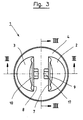
- Figure 3 shows a plan view of a second embodiment the device 1 in an open representation and Figure 4 is a sectional view according to the section line II-II of Figure 3.
- Die second embodiment of the device 1 also has a round support plate 4 and rounded jaws 2, 3 on, both together the shape of a Form hemisphere.
- a difference from the figure 1 and 2 consists of the selection of a different spring arrangement.
- the jaws 2, 3 are with their guide bases 15, 16 also in a slot 17 performed, the molded bracket 18, 19 each has a bore 30, 31 cut open downward, in which a bolt 32 lies, which in turn is in two holes 33, 34 of the support bracket 20, 21 of the support plate 4 is held captive. Alternatively there is the possibility of the bolt 32 in the edge 22 of the carrier plate 4 to attach.
- the jaws 2, 3 are during assembly simply through the cut down Bores 30, 31 clamped on the bolt 32.
- On the bolt 32 lies between each Support brackets 20, 21 of the support plate 4 and the brackets 18, 19 of the jaws 2, 3 a spring 23, 24, which in the open representation of the device 1 are compressed.
- the jaws 2, 3 point an inner surface 7, 8 as shown in FIGS. 1 and 2, being characterized by the hemispherical shape the two clamping jaws 2, 3 the middle regions 11, 12 opens in a ring on the surface of the sphere and the Bevels 9, 10 each form a circular section.
- Figure 5 shows a sectional view of the device 1 along the section line III-III from Figure 3, from the the guide slot 17 of the carrier plate is particularly good 4 and the guide base 5 of the jaws 2, 3 is recognizable.
- the console is on the guide base 5 18 and 19 formed in one piece, the guide slot 17 engages behind, so that the jaws 2, 3 are not can fall out of the leadership and that in the Center has the bore 30 or 31 in which the bolt 32 is mounted together with the springs 23, 24.
- the Carrier plate has on its underside, as already in FIG.
- a base plate 25, by a spring 26 in a groove 27 of the carrier plate 4 is held, the circular shape of the Carrier plate 4 and the bottom plate 25 the device is rotatable and the position of the jaws 2, 3 can be changed in one level.
- the carrier plate 4 in a large bore be included with spring 26, which in any Base body can be provided.
- Figure 6 shows a single rectangular support plate 4 of the jaws 2, 3, in which a split Slot 17 for receiving a guide base 5 of the jaws 2 or 3 is present.
- FIG. 7 shows a top view of a further exemplary embodiment the device 1 in a closed representation.
- the device 1 has two centrally arranged clamping jaws 40, 41 on a carrier body arranged as a round carrier plate 40.
- the outer shape of the jaws 41, 42 or the carrier plate 40 can again be chosen freely become.
- the jaws 41, 42 are opposite one another arranged and are in by spring force a rest position compressed.
- the difference to the first embodiment according to FIG Jaws 41, 42 each have a semicircular shape Recess 43, 44, which in the rest position of the compressed jaws 41, 42 one circular opening 45 result, the wall cylindrical or conical, as shown in Figure 8, can be trained.
- the carrier plate in a bottom plate is attached, for example on an inkwell can be designed to be screwed on or with the carrier plate 40 itself a corresponding internal thread can have.
- This continues to be flat Objects can be pinched easily the inner surfaces 46, 47 each have a bevel 48, 49 on.
- the inner surfaces 46, 47 can in the middle Area additionally rounded or alternatively elliptical be, as in the embodiment of Figure 1 to place items even across the jaws 41, 42 record.
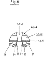
- FIG. 8 shows a single jaw 41, 42 in a side view with a view of the inner surface 46, 47 shown.
- the inner surface 46, 47 has a conical Recess 43, 44, being perpendicular to the recess 43, 44 the inner surface 46, 47 is additionally round is. So that it can be inserted vertically the object is created is the jaw 41, 42 off-center with two guide bases 50, 51 in two guide slots 52, 53 of the carrier plate 40 guided, which are parallel and spaced from each other run, as can be seen from Figure 9.
- the carrier plate 40 also has a central through hole of the object.
- Possibility not two, but three or four jaws to use which are arranged in a star shape are and an angular distance of 120 or 90 degrees exhibit. The guidance of these jaws can then each from a single guide base and Guide slot exist, which are also star-shaped are arranged.
- two guide blocks each 50, 51 and two bolts are provided for fastening.
- the guide bases are designed to accommodate the bolts 50, 51 each have a bore cut open downwards 54, 55 in which the eccentrically mounted Bolts are included.
- FIG. 9 shows the carrier plate 40 with the two in parallel arranged guide slots 52, 53 and one central bore 58 to insert through the object to be able to.
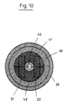
- Figure 10 shows a section of the assembled device 1 through the carrier plate 40, which additionally a Has chamfer 59. In the middle of the device the opening 45 can be seen, which between the Guide slots 51, 52 lies in which the clamping jaws 41, 42 are guided.
- the aforementioned embodiments of the device 1 can be combined with each other or in multiple arrangement on a carrier plate 4, 40 or be a carrier body.
Landscapes
- Engineering & Computer Science (AREA)
- Mechanical Engineering (AREA)
- Clamps And Clips (AREA)
- Supports Or Holders For Household Use (AREA)
- Eye Examination Apparatus (AREA)
- Manipulator (AREA)
Applications Claiming Priority (4)
| Application Number | Priority Date | Filing Date | Title |
|---|---|---|---|
| DE4338052A DE4338052C2 (de) | 1993-11-08 | 1993-11-08 | Vorrichtung zur Aufnahme und Halterung von runden oder eckigen Gegenständen |
| DE4338052 | 1993-11-08 | ||
| DE9406937U | 1994-04-27 | ||
| DE9406937U DE9406937U1 (de) | 1993-11-08 | 1994-04-27 | Vorrichtung zur Aufnahme und Halterung von runden oder eckigen Gegenständen |
Publications (3)
| Publication Number | Publication Date |
|---|---|
| EP0651966A1 EP0651966A1 (de) | 1995-05-10 |
| EP0651966B1 EP0651966B1 (de) | 1998-12-02 |
| EP0651966B2 true EP0651966B2 (de) | 2003-03-12 |
Family
ID=25931050
Family Applications (1)
| Application Number | Title | Priority Date | Filing Date |
|---|---|---|---|
| EP94117346A Expired - Lifetime EP0651966B2 (de) | 1993-11-08 | 1994-11-03 | Vorrichtung zur Aufnahme und Halterung von runden und eckigen Gegenständen |
Country Status (3)
| Country | Link |
|---|---|
| EP (1) | EP0651966B2 (es) |
| AT (1) | ATE173900T1 (es) |
| ES (1) | ES2128489T5 (es) |
Cited By (1)
| Publication number | Priority date | Publication date | Assignee | Title |
|---|---|---|---|---|
| DE202015004430U1 (de) | 2015-06-23 | 2015-08-17 | Erich Mekyska | Klemmvorrichtung |
Families Citing this family (4)
| Publication number | Priority date | Publication date | Assignee | Title |
|---|---|---|---|---|
| DE20118073U1 (de) * | 2001-11-08 | 2002-02-21 | Erich Mekyska KG, 75177 Pforzheim | Halterung für sphärische und flache Gegenstände |
| US7356883B2 (en) | 2001-11-08 | 2008-04-15 | Erich Mekyska | Holder for securing objects |
| CN108092119B (zh) * | 2016-11-23 | 2024-02-27 | 阿特斯阳光电力集团股份有限公司 | 连接器紧固装置 |
| CN115284240B (zh) * | 2022-09-28 | 2022-12-27 | 山西天宝集团有限公司 | 一种基于风电法兰摆放用的固定装置及其方法 |
Family Cites Families (22)
| Publication number | Priority date | Publication date | Assignee | Title |
|---|---|---|---|---|
| DE8220423U1 (de) * | 1982-10-21 | Hetal-Werke Franz Hettich Gmbh & Co, 7297 Alpirsbach | Rasterung zur Fixierung verschwenkbarer Teile | |
| DE7415942U (de) * | 1974-09-26 | Springfix Befestigungstechnik Gmbh | Federnde Halteklammer | |
| DE355861C (de) * | 1922-07-03 | Robert Herold Jr | Waescheklammer aus Holz | |
| DE343584C (es) * | ||||
| DE7905903U1 (de) | 1979-05-31 | Fa. H.D. Grossmann, 5760 Arnsberg | Klammer | |
| US670446A (en) * | 1900-02-08 | 1901-03-26 | Patent Case Company | Holding-block for cases and boxes. |
| GB355585A (en) * | 1930-10-31 | 1931-08-27 | Daniel Nachtigal | Improvements in and relating to broom or like holders |
| US2622835A (en) * | 1950-10-06 | 1952-12-23 | Ippolito Domenick | Doll stand |
| CH342339A (de) * | 1956-03-28 | 1959-11-15 | Stadelmann Weber Elisabeth | Vorrichtung zum Aufhängen von mit Stielen versehenen Geräten aller Art |
| DE6813372U (de) * | 1968-12-27 | 1969-04-10 | Robert Sen Bihler | Selbstklemmende haltevorrichtung fuer tuben, becher od. dgl, toilette-bedarfsartikel |
| DE7340820U (de) * | 1973-11-15 | 1974-02-21 | Beyertz K | Klammer zur Befestigung von Gegenständen an gespannten Leinen, Drähten od. dgl |
| GB2029490B (en) * | 1978-09-06 | 1982-07-14 | Mcdowall K | Clamp |
| SE8302522L (sv) * | 1983-05-03 | 1984-11-04 | Martin Nilsson | Klemanordning |
| US4635801A (en) * | 1983-05-17 | 1987-01-13 | Meir Oren | Device for holding and storing articles |
| DE3437806C2 (de) * | 1984-10-16 | 1986-10-16 | Dieter 3052 Bad Nenndorf Rasche | Schloß |
| DE8530432U1 (de) | 1985-10-23 | 1985-12-19 | Heidt, Geza, Dr., 1000 Berlin | Klammer |
| DE3818031A1 (de) * | 1988-05-27 | 1989-11-30 | Brauckmann & Proebsting | Vorrichtung zur halterung von werkzeugen |
| DE3941925A1 (de) * | 1988-12-20 | 1990-06-21 | Bergmann Franz | Zahnpastahalter |
| US4909467A (en) * | 1989-02-09 | 1990-03-20 | Shan Pao Chang | Holder for bottles and tools |
| US5154380A (en) * | 1990-08-31 | 1992-10-13 | Mihai Risca | Container holder |
| DE9216190U1 (de) * | 1992-11-27 | 1993-01-21 | Wang, Chin-Yang, Panchiao, Taipeh | Halterung für ein Mobiltelefon |
| DE9216626U1 (de) * | 1992-12-05 | 1993-04-08 | Wang, Chin-Yang, Panchiao, Taipeh | Vorrichtung zur Halterung eines Mobiltelefons |
-
1994
- 1994-11-03 EP EP94117346A patent/EP0651966B2/de not_active Expired - Lifetime
- 1994-11-03 ES ES94117346T patent/ES2128489T5/es not_active Expired - Lifetime
- 1994-11-03 AT AT94117346T patent/ATE173900T1/de not_active IP Right Cessation
Cited By (1)
| Publication number | Priority date | Publication date | Assignee | Title |
|---|---|---|---|---|
| DE202015004430U1 (de) | 2015-06-23 | 2015-08-17 | Erich Mekyska | Klemmvorrichtung |
Also Published As
| Publication number | Publication date |
|---|---|
| ES2128489T5 (es) | 2003-12-16 |
| EP0651966A1 (de) | 1995-05-10 |
| ES2128489T3 (es) | 1999-05-16 |
| EP0651966B1 (de) | 1998-12-02 |
| ATE173900T1 (de) | 1998-12-15 |
Similar Documents
| Publication | Publication Date | Title |
|---|---|---|
| DE4338052C2 (de) | Vorrichtung zur Aufnahme und Halterung von runden oder eckigen Gegenständen | |
| DE69316423T2 (de) | Ablagemechanismus für den Eingabestift an einem Gerät mit einer Eingabefläche | |
| DE3690023C1 (de) | Vorrichtung zum Eindrehen von Schrauben mit Unterlegscheiben | |
| DE3710016A1 (de) | Aufnahmeelement, insbesondere fuer die medizintechnik | |
| EP2039566B1 (de) | Vorrichtung zum Halten von Getränkebehältern | |
| DE4313718C2 (de) | Vorrichtung zur Halterung eines Sägeblattes | |
| EP2199001B1 (de) | Stichsäge mit einer Sägeblattaufnahme | |
| DE3141248C2 (de) | Einrichtung zum Zuführen von Schrauben für einen motorbetriebenen Schraubenzieher | |
| EP0651966B2 (de) | Vorrichtung zur Aufnahme und Halterung von runden und eckigen Gegenständen | |
| DE19708587C1 (de) | Lösbare Halterung für ein Blatt am Haltearm eines chirurgischen Retraktors | |
| EP1888280B1 (de) | Verbindung zwischen zwei werkzeugteilen | |
| EP0611535A1 (de) | An einer Begrenzungswand einer Abstell-/Ablagefläche anzubringender positionierbarer Teiler für diese Fläche | |
| EP0094561A2 (de) | Handvorrichtung für die Handhabung von Reisszwecken, Reissnägeln, Heftzwecken od. dgl. Nägeln | |
| DE20105767U1 (de) | Tragbare Werkzeugmaschine mit integrierter Bitschublade | |
| DE10011479A1 (de) | Klemmvorrichtung | |
| EP2845693B1 (de) | Adapterverbindung für ein Werkzeug | |
| DE69809550T2 (de) | Klemmvorrichtung | |
| DE19725401C1 (de) | Bohrvorrichtung mit Begrenzung des Bohrweges | |
| DE2511319C3 (de) | Nasenplatte für ein Eintreibgerät | |
| DE8815530U1 (de) | Schraubenzieher | |
| DE1554253C3 (de) | Dose für Möbelscharniere | |
| DE4241493C2 (de) | Werkzeughalter | |
| DE3037426C2 (de) | Zwinge für das Bauwesen | |
| DE1921823C3 (de) | Hin und her bewegbare, gleitende Verbindung mit Verriegelung und Entriegelung des Gleitens sowie Zirkel mit einer solchen Verbindung | |
| DE3234773A1 (de) | Werkzeugablageeinrichtung |
Legal Events
| Date | Code | Title | Description |
|---|---|---|---|
| PUAI | Public reference made under article 153(3) epc to a published international application that has entered the european phase |
Free format text: ORIGINAL CODE: 0009012 |
|
| AK | Designated contracting states |
Kind code of ref document: A1 Designated state(s): AT BE CH DE DK ES FR GB IT LI NL SE |
|
| 17P | Request for examination filed |
Effective date: 19950930 |
|
| GRAG | Despatch of communication of intention to grant |
Free format text: ORIGINAL CODE: EPIDOS AGRA |
|
| 17Q | First examination report despatched |
Effective date: 19970804 |
|
| GRAG | Despatch of communication of intention to grant |
Free format text: ORIGINAL CODE: EPIDOS AGRA |
|
| TPAD | Observations filed by third parties |
Free format text: ORIGINAL CODE: EPIDOS TIPA |
|
| GRAG | Despatch of communication of intention to grant |
Free format text: ORIGINAL CODE: EPIDOS AGRA |
|
| GRAH | Despatch of communication of intention to grant a patent |
Free format text: ORIGINAL CODE: EPIDOS IGRA |
|
| GRAH | Despatch of communication of intention to grant a patent |
Free format text: ORIGINAL CODE: EPIDOS IGRA |
|
| GRAA | (expected) grant |
Free format text: ORIGINAL CODE: 0009210 |
|
| AK | Designated contracting states |
Kind code of ref document: B1 Designated state(s): AT BE CH DE DK ES FR GB IT LI NL SE |
|
| REF | Corresponds to: |
Ref document number: 173900 Country of ref document: AT Date of ref document: 19981215 Kind code of ref document: T |
|
| REG | Reference to a national code |
Ref country code: CH Ref legal event code: EP |
|
| REF | Corresponds to: |
Ref document number: 59407387 Country of ref document: DE Date of ref document: 19990114 |
|
| ITF | It: translation for a ep patent filed | ||
| PG25 | Lapsed in a contracting state [announced via postgrant information from national office to epo] |
Ref country code: SE Free format text: LAPSE BECAUSE OF FAILURE TO SUBMIT A TRANSLATION OF THE DESCRIPTION OR TO PAY THE FEE WITHIN THE PRESCRIBED TIME-LIMIT Effective date: 19990302 Ref country code: DK Free format text: LAPSE BECAUSE OF FAILURE TO SUBMIT A TRANSLATION OF THE DESCRIPTION OR TO PAY THE FEE WITHIN THE PRESCRIBED TIME-LIMIT Effective date: 19990302 |
|
| GBT | Gb: translation of ep patent filed (gb section 77(6)(a)/1977) |
Effective date: 19990304 |
|
| ET | Fr: translation filed | ||
| REG | Reference to a national code |
Ref country code: CH Ref legal event code: NV Representative=s name: R. A. EGLI & CO. PATENTANWAELTE |
|
| REG | Reference to a national code |
Ref country code: ES Ref legal event code: FG2A Ref document number: 2128489 Country of ref document: ES Kind code of ref document: T3 |
|
| PLBQ | Unpublished change to opponent data |
Free format text: ORIGINAL CODE: EPIDOS OPPO |
|
| PLBI | Opposition filed |
Free format text: ORIGINAL CODE: 0009260 |
|
| 26 | Opposition filed |
Opponent name: HERBERT RICHTER METALLWAREN-APPARATEBAU GMBH & CO. Effective date: 19990706 |
|
| PLBF | Reply of patent proprietor to notice(s) of opposition |
Free format text: ORIGINAL CODE: EPIDOS OBSO |
|
| PLBF | Reply of patent proprietor to notice(s) of opposition |
Free format text: ORIGINAL CODE: EPIDOS OBSO |
|
| PLBF | Reply of patent proprietor to notice(s) of opposition |
Free format text: ORIGINAL CODE: EPIDOS OBSO |
|
| PLBQ | Unpublished change to opponent data |
Free format text: ORIGINAL CODE: EPIDOS OPPO |
|
| PLAB | Opposition data, opponent's data or that of the opponent's representative modified |
Free format text: ORIGINAL CODE: 0009299OPPO |
|
| R26 | Opposition filed (corrected) |
Opponent name: HERBERT RICHTER METALLWAREN-APPARATEBAU GMBH & CO. Effective date: 19990706 |
|
| NLR1 | Nl: opposition has been filed with the epo |
Opponent name: HERBERT RICHTER METALLWAREN-APPARATEBAU GMBH & CO. |
|
| REG | Reference to a national code |
Ref country code: GB Ref legal event code: IF02 |
|
| PLAW | Interlocutory decision in opposition |
Free format text: ORIGINAL CODE: EPIDOS IDOP |
|
| PLAW | Interlocutory decision in opposition |
Free format text: ORIGINAL CODE: EPIDOS IDOP |
|
| PUAH | Patent maintained in amended form |
Free format text: ORIGINAL CODE: 0009272 |
|
| STAA | Information on the status of an ep patent application or granted ep patent |
Free format text: STATUS: PATENT MAINTAINED AS AMENDED |
|
| 27A | Patent maintained in amended form |
Effective date: 20030312 |
|
| AK | Designated contracting states |
Designated state(s): AT BE CH DE DK ES FR GB IT LI NL SE |
|
| REG | Reference to a national code |
Ref country code: CH Ref legal event code: AEN Free format text: AUFRECHTERHALTUNG DES PATENTES IN GEAENDERTER FORM |
|
| NLR2 | Nl: decision of opposition |
Effective date: 20030312 |
|
| NLR3 | Nl: receipt of modified translations in the netherlands language after an opposition procedure | ||
| ET3 | Fr: translation filed ** decision concerning opposition | ||
| REG | Reference to a national code |
Ref country code: ES Ref legal event code: DC2A Date of ref document: 20030703 Kind code of ref document: T5 |
|
| PGFP | Annual fee paid to national office [announced via postgrant information from national office to epo] |
Ref country code: FR Payment date: 20061117 Year of fee payment: 13 |
|
| PGFP | Annual fee paid to national office [announced via postgrant information from national office to epo] |
Ref country code: BE Payment date: 20061122 Year of fee payment: 13 Ref country code: AT Payment date: 20061122 Year of fee payment: 13 |
|
| PGFP | Annual fee paid to national office [announced via postgrant information from national office to epo] |
Ref country code: GB Payment date: 20061123 Year of fee payment: 13 Ref country code: ES Payment date: 20061123 Year of fee payment: 13 Ref country code: CH Payment date: 20061123 Year of fee payment: 13 |
|
| PGFP | Annual fee paid to national office [announced via postgrant information from national office to epo] |
Ref country code: IT Payment date: 20061130 Year of fee payment: 13 |
|
| PGFP | Annual fee paid to national office [announced via postgrant information from national office to epo] |
Ref country code: NL Payment date: 20080220 Year of fee payment: 14 |
|
| BERE | Be: lapsed |
Owner name: *MEKYSKA ERICH Effective date: 20071130 |
|
| GBPC | Gb: european patent ceased through non-payment of renewal fee |
Effective date: 20071103 |
|
| PG25 | Lapsed in a contracting state [announced via postgrant information from national office to epo] |
Ref country code: LI Free format text: LAPSE BECAUSE OF NON-PAYMENT OF DUE FEES Effective date: 20071130 Ref country code: CH Free format text: LAPSE BECAUSE OF NON-PAYMENT OF DUE FEES Effective date: 20071130 |
|
| REG | Reference to a national code |
Ref country code: CH Ref legal event code: PL |
|
| PG25 | Lapsed in a contracting state [announced via postgrant information from national office to epo] |
Ref country code: AT Free format text: LAPSE BECAUSE OF NON-PAYMENT OF DUE FEES Effective date: 20071103 |
|
| PG25 | Lapsed in a contracting state [announced via postgrant information from national office to epo] |
Ref country code: BE Free format text: LAPSE BECAUSE OF NON-PAYMENT OF DUE FEES Effective date: 20071130 |
|
| REG | Reference to a national code |
Ref country code: FR Ref legal event code: ST Effective date: 20080930 |
|
| PG25 | Lapsed in a contracting state [announced via postgrant information from national office to epo] |
Ref country code: GB Free format text: LAPSE BECAUSE OF NON-PAYMENT OF DUE FEES Effective date: 20071103 |
|
| REG | Reference to a national code |
Ref country code: ES Ref legal event code: FD2A Effective date: 20071105 |
|
| PG25 | Lapsed in a contracting state [announced via postgrant information from national office to epo] |
Ref country code: FR Free format text: LAPSE BECAUSE OF NON-PAYMENT OF DUE FEES Effective date: 20071130 Ref country code: ES Free format text: LAPSE BECAUSE OF NON-PAYMENT OF DUE FEES Effective date: 20071105 |
|
| PG25 | Lapsed in a contracting state [announced via postgrant information from national office to epo] |
Ref country code: NL Free format text: LAPSE BECAUSE OF NON-PAYMENT OF DUE FEES Effective date: 20090601 |
|
| NLV4 | Nl: lapsed or anulled due to non-payment of the annual fee |
Effective date: 20090601 |
|
| PG25 | Lapsed in a contracting state [announced via postgrant information from national office to epo] |
Ref country code: IT Free format text: LAPSE BECAUSE OF NON-PAYMENT OF DUE FEES Effective date: 20071103 |
|
| PGFP | Annual fee paid to national office [announced via postgrant information from national office to epo] |
Ref country code: DE Payment date: 20140130 Year of fee payment: 20 |
|
| REG | Reference to a national code |
Ref country code: DE Ref legal event code: R071 Ref document number: 59407387 Country of ref document: DE |