EP0652081A1 - Werkzeugverlängerungseinrichtung - Google Patents
Werkzeugverlängerungseinrichtung Download PDFInfo
- Publication number
- EP0652081A1 EP0652081A1 EP93308883A EP93308883A EP0652081A1 EP 0652081 A1 EP0652081 A1 EP 0652081A1 EP 93308883 A EP93308883 A EP 93308883A EP 93308883 A EP93308883 A EP 93308883A EP 0652081 A1 EP0652081 A1 EP 0652081A1
- Authority
- EP
- European Patent Office
- Prior art keywords
- tool
- cradle
- spar
- control arm
- main spar
- Prior art date
- Legal status (The legal status is an assumption and is not a legal conclusion. Google has not performed a legal analysis and makes no representation as to the accuracy of the status listed.)
- Granted
Links
- 230000009467 reduction Effects 0.000 claims description 2
- 238000009966 trimming Methods 0.000 description 11
- 239000004033 plastic Substances 0.000 description 3
- 229920003023 plastic Polymers 0.000 description 3
- 229910000838 Al alloy Inorganic materials 0.000 description 2
- 230000000712 assembly Effects 0.000 description 2
- 238000000429 assembly Methods 0.000 description 2
- 239000011449 brick Substances 0.000 description 2
- 238000010276 construction Methods 0.000 description 2
- 230000009977 dual effect Effects 0.000 description 2
- 230000005484 gravity Effects 0.000 description 2
- 238000001746 injection moulding Methods 0.000 description 2
- 238000004519 manufacturing process Methods 0.000 description 2
- 238000000034 method Methods 0.000 description 2
- OKTJSMMVPCPJKN-UHFFFAOYSA-N Carbon Chemical compound [C] OKTJSMMVPCPJKN-UHFFFAOYSA-N 0.000 description 1
- 230000009471 action Effects 0.000 description 1
- 230000008901 benefit Effects 0.000 description 1
- 229910052799 carbon Inorganic materials 0.000 description 1
- 238000002485 combustion reaction Methods 0.000 description 1
- 239000002131 composite material Substances 0.000 description 1
- 239000004020 conductor Substances 0.000 description 1
- 238000004512 die casting Methods 0.000 description 1
- 239000000835 fiber Substances 0.000 description 1
- 239000003562 lightweight material Substances 0.000 description 1
- 239000000463 material Substances 0.000 description 1
- 238000012986 modification Methods 0.000 description 1
- 230000004048 modification Effects 0.000 description 1
- 230000007935 neutral effect Effects 0.000 description 1
- 239000003973 paint Substances 0.000 description 1
- 238000013138 pruning Methods 0.000 description 1
- 230000000717 retained effect Effects 0.000 description 1
- 239000000243 solution Substances 0.000 description 1
- 238000005507 spraying Methods 0.000 description 1
Images




Classifications
-
- A—HUMAN NECESSITIES
- A01—AGRICULTURE; FORESTRY; ANIMAL HUSBANDRY; HUNTING; TRAPPING; FISHING
- A01G—HORTICULTURE; CULTIVATION OF VEGETABLES, FLOWERS, RICE, FRUIT, VINES, HOPS OR SEAWEED; FORESTRY; WATERING
- A01G3/00—Cutting implements specially adapted for horticultural purposes; Delimbing standing trees
- A01G3/04—Apparatus for trimming hedges, e.g. hedge shears
- A01G3/047—Apparatus for trimming hedges, e.g. hedge shears portable
- A01G3/053—Apparatus for trimming hedges, e.g. hedge shears portable motor-driven
Definitions
- This invention relates to an attachment for a tool, (typically a power tool) to extend the normal range of operation to an increased distance from the user, especially in height.
- a tool typically a power tool
- the invention is of particular application to a power pruning saw or more especially a hedge trimmer, but is not limited to such devices which are mentioned by way of example only.
- a tool extension attachment comprising a main spar, a cradle pivotally mounted at a forward end of the main spar for detachably holding the tool, handle means joined to the spar at a position intermediate the ends thereof, control means on or adjacent the handle means for controlling operation of the tool, control arm means mounted for movement relative to the main spar and force transfer means interconnecing the control arm and the tool cradle whereby at least the angle of tilt of the axis of the tool can be adjusted relative to the axis of the main spar.
- the cradle and the control arm are pivotally mounted relative to the main spar and interconnected so that not only the tilt but also the pan of for example a cutting blade driven by the tool can be adjusted, i.e. the angle of orientation of the cutting blade of the tool about its axis can be adjusted.
- Tilt of the tool cradle is preferably controlled by pivotal forward and backward movement of the control arm relative to the length of the main spar, whilst pan may be controlled by rotation of the control arm about the main spar.
- This control can be enabled by use of two force transfer means interconnecting the control arm and the cradle.
- the control means may for example control the supply of electrical power to an electrically powered tool from the region of the handle, where a socket may be provided for connection of a power supply lead.
- a socket may be provided for connection of a power supply lead.
- the in-built power switch on the tool may be fixed in the "on" condition, and a power connecting lead extending from the handle region through the said control means will plug into the in-built power supply socket on the power tool.
- This connecting lead may incorporate a coiled section to accommodate expansion and reduction in length when the power tool is adjusted in position.
- the degree of tilt available will preferably be at least 90 degrees so that, in the case of a hedge trimmer for example, the horizontal flat top of a high hedge can be trimmed as well as its vertical sides.
- the rear end of the main spar is adapted to carry a counterweight.
- a shoulder strap may be provided for assistance in supporting the weight of the equipment.
- a shoulder pad or harness may be fitted to the spar between the handle means and the rear end of the main spar, so that the latter can be supported on the shoulder of a user.
- the control arm preferably extends laterally on opposite sides of the spar and includes downward extensions forming two handles on opposite sides of the main spar, to be gripped by both hands of the user in much the same way as a bicycle handlebar is held by a cyclist, to enable the user to both lift, control and stee the main spar and the tool hand grips may be provided on the lower ends of the downwardly extending handles.
- the position of the control arm and/or handle means along the length of the spar may be adjustable, as may be the position and/or weight of the counterweight, to enclose different tool weights to be balanced.
- the force transfer means may comprise rods or cables or levers or any combination thereof.
- the control arm may for example comprise a lever pivotally mounted on the spar on the handle means or a pistol grip and trigger likewise mounted.
- Quick release locking means may be provided to allow the control means and/or the control arm to be secured in a desired position.
- the invention also extends to a kit of parts for construction of the afore-described tool extension attachment.
- a kit of parts comprising a main spar which can be assembled from two or more spar lengths, means for assembly of a tool cradle and for mounting said cradle to a forward end of the main spar, handle means mounted on or mountable on the main spar intermediate the ends thereof said handle incorporating a control means for controlling operation of a tool carried by the cradle, and either comprising or having mounted near thereto control arm means movable relative to the main spar and at least one force transfer means interconnectable between the control arm means and the cradle to enable at least the tilt of a tool carried thereon to be adjusted.
- the invention has particular applicability to an extension attachment for a hedge trimmer but any power tool may be fitted to an extension attachment embodying the invention.
- the device is especially intended to be supplied in a part-assembled form, so that the packaged product is no longer than 1250 mm, for convenience of palleted transport, and easy display on shop shelving.
- the drawings show a typical and commonly used model of hedge trimmer, but the device is adaptable to enable a range of different models to be mounted thereto.
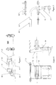
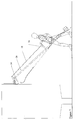
- the device or attachment comprises a main spar 10, a cradle 12 for the trimmer 14 pivotally mounted at the front end of the main spar, a control arm 16, two thrust transmitting means such as rods 18 interconnecting the control arm 16 and the cradle 12, a handle 20, an on/off switch 22 on the handle, a cable 24 connecting a power input socket 26 on the handle with a power input socket on the trimmer 14, a counterweight carrier 28 and a shoulder strap 30.
- the main spar 10 is made of tube, in three pieces that fit inside each other, and bolted together by the user, of strong, lightweight material, e.g. heat treated aluminium alloy or carbon fibre composite.
- the trimmer cradle 12 is a fabricated assembly made up of an inverted "U", of a channel section 32, that fits over the cross handle of the trimmer. Aircraft type rigging pins 34 with sprung ball detents are inserted through holes in this U member, to allow quick attachment or removal of the trimmer. Holes in different positions as necessary can be used for different models of trimmer. Extended side plates are permanently attached to the U member, and have pivots for a tubular axle beam 35, and clevis bearings 36 for control rods at the top. The axle beam has an offset clevis bracket, which is attached to the main spar pivotally at right angles to the axle.
- the control arm 16 is a bent tube of inverted "L" shape, fitted with a cycle type handgrip 38, that is mounted pivotally and axial vertically in a trunnion 40 that is pivotally attached to the main spar, in a direction parallel to the trimmer cradle axle.
- the position of this pivot is approximately two thirds of the way along the main spar, from the trimmer end.
- a cross tree beam 42 is pivotally mounted parallel to the trunnion axis, which carries a control rod clevis at each end.
- the thrust transmitting rods 18 are preferably also made of tube, each in two main parts, bolted together by the strong material, e.g. aluminium alloy.
- a through hole is drilled near to each end, parallel in axis.
- a domed plastics insert fits in each end, and is secured by the pivot pin fitted through the clevises at the control arm and trimmer cradle assemblies.
- the clevises form universal joints, with horizontal "U" members that pivot around their respective axles and plastics shoulder bushes, retained by pivot pins, with the domed inserts bearing against the axles, as indicated at 44.
- the thrust transmitting rods 18 may be replaced by levers or cables, typically a Bowden cable or cables.
- the handle 20 is made of non-conducting material for electrical safety, and is typically a two part injection moulding.
- the handle 20 is bolted to the main spar 10 a short way behind the control arm, and incorporates a momentary action push button switch 22, a standard garden appliance connector 26, internal cable clamp 46, and a grommeted cable outlet 48. Internal wiring connects the connector to the switch, where the outlet cable is also connected, and clamped before its outlet through the grommeted hole at the front.
- the cable 24 is routed from the handle around the main spar to a cable clamp on the bottom surface, and thence to the trimmer, terminating in a standard garden appliance connector. It can thus be seen that the supply cable lead can conveniently be plugged directly into the trimmer for independent use, or into the handle of the extension arm for use in that mode.
- the outlet cable has part of its length formed into a lightly sprung coiled length 50, which helps to tidily manage the variance in distance between the trimmer and the control arm during operation.
- the counterweight carrier 28 is a formed tray, mounted to the extreme end of the main spar, and is proportioned to accept a weight to counterbalance the moment of the front extension with the trimmer attached.
- This weight can conveniently be, e.g., two house bricks, which are commonly available. An elastic strap retains the bricks properly in place.
- the shoulder strap 30 is a golf bag type strap, suitably padded for comfort, and pivotally connected to an eye-bolt on the main spar, between the control arm and the handle, at the notional centre of gravity of the assembled device.
- the integral switch on the hedge trimmer is set to permanently on and, for safety, before the supply cable lead is plugged into the handle of the extension arm device.
- Some trimmers cannot be switched permanently on, so a supplied plastic clamp would be used in this case.
- the device should approximately balance horizontally for the most convenient use.
- the user When the mode is for trimming the extremes in height, the user has to lift the device via the handle, to obtain extra reach. The effort in doing this is more than for the lower areas, as the benefit of support from the shoulder strap is lost, but would be occasional, not continuous effort.
- the overall weight of the device with trimmer and counterbalance is approximately the same as a full set of golf clubs, and for the average hedge, the time spent trimming would be minutes rather than hours.
- spar 10' of the extension attachment is supported on a padded shoulder harness 53, with a quick release compliant pivot at its longitudinal centre of gravity. Operation of the attachment is achieved by use of the handle assembly 55 as shown in Figure 10.
- the handle assembly 55 includes dual control arms 57, 57' with hand grips 38, 38' connected by a torsion bar 59. Differential fore and aft movement of the arms 57, 57', enables pan adjustment. The arms 57, 57' spring back to their neutral position on relase due to the torsion bar.
- a switch 62 is provided on the handle assembly to control the supply of power to the tool.
- This embodiment of the invention provides greater reach due to the pivot point being on the shoulder, less chance of the conterbalance weight hitting the ground due to increased elevation of the pivot point, and greater control as all functions are controlled by dual handles.
- the opposed ends 64, 66 of the two control lever arms 57, 57' are received in a bearing tube 68 which is carried transversely relative to the spar 10' by a bracket 70 to which is secured a clamp 72 for clamping around the tubular spar 10'.
- the ends 64, 66 are hollow to allow the strip torsion bar 59 to extend therethrough as shown in Figure 10.
- Pins 74, 76 driven through holes in the tubular lever ends 64, 66 and through aligned holes in the ends of the torsion bar 59, not only key the lever arms to the bar, but also retain the lever in the sleeve (tube) 68.
- the tool may be electrically powered as illustrated herein, or air-line powered or self-powered for example by an internal combustion engine or by any other known power means.
Landscapes
- Life Sciences & Earth Sciences (AREA)
- Biodiversity & Conservation Biology (AREA)
- Ecology (AREA)
- Forests & Forestry (AREA)
- Environmental Sciences (AREA)
- Harvester Elements (AREA)
Priority Applications (3)
| Application Number | Priority Date | Filing Date | Title |
|---|---|---|---|
| GB9209949A GB2266682B (en) | 1992-05-08 | 1992-05-08 | Power tool extension attachment |
| DE69327652T DE69327652D1 (de) | 1993-11-08 | 1993-11-08 | Werkzeugverlängerungseinrichtung |
| EP93308883A EP0652081B1 (de) | 1992-05-08 | 1993-11-08 | Werkzeugverlängerungseinrichtung |
Applications Claiming Priority (2)
| Application Number | Priority Date | Filing Date | Title |
|---|---|---|---|
| GB9209949A GB2266682B (en) | 1992-05-08 | 1992-05-08 | Power tool extension attachment |
| EP93308883A EP0652081B1 (de) | 1992-05-08 | 1993-11-08 | Werkzeugverlängerungseinrichtung |
Publications (2)
| Publication Number | Publication Date |
|---|---|
| EP0652081A1 true EP0652081A1 (de) | 1995-05-10 |
| EP0652081B1 EP0652081B1 (de) | 2000-01-19 |
Family
ID=26134536
Family Applications (1)
| Application Number | Title | Priority Date | Filing Date |
|---|---|---|---|
| EP93308883A Expired - Lifetime EP0652081B1 (de) | 1992-05-08 | 1993-11-08 | Werkzeugverlängerungseinrichtung |
Country Status (2)
| Country | Link |
|---|---|
| EP (1) | EP0652081B1 (de) |
| GB (1) | GB2266682B (de) |
Cited By (2)
| Publication number | Priority date | Publication date | Assignee | Title |
|---|---|---|---|---|
| GB2417182A (en) * | 2004-08-17 | 2006-02-22 | Brian Hartley | Hedge trimmer with extension handle |
| ES2258882A1 (es) * | 2003-11-25 | 2006-09-01 | Jose Ramon Bernal Valderrama | Dispositivo recogedor perfeccionado. |
Families Citing this family (10)
| Publication number | Priority date | Publication date | Assignee | Title |
|---|---|---|---|---|
| GB2266682B (en) * | 1992-05-08 | 1995-06-07 | Peter John Dennis Bailey | Power tool extension attachment |
| TW292965B (en) * | 1995-08-07 | 1996-12-11 | Fiskars Inc | Tool for performing lopping, trimming, pruning and similar cutting operations |
| GB2325387A (en) * | 1997-05-23 | 1998-11-25 | Black & Decker Inc | Hedge trimmer |
| US8186066B2 (en) | 2002-11-19 | 2012-05-29 | Husqvarna Ab | Motor driven tool such as a pole hedge trimmer with a locking mechanism for the turnable cutting unit |
| US7093366B2 (en) | 2003-06-23 | 2006-08-22 | William Edward Black | Ground supported portable tool guide |
| US7752760B2 (en) * | 2005-06-30 | 2010-07-13 | Black & Decker, Inc. | Portable trimmer having rotatable power head |
| US7640941B2 (en) | 2006-03-22 | 2010-01-05 | Black & Decker, Inc. | Brush and roller cleaner |
| USD560045S1 (en) | 2006-03-22 | 2008-01-15 | Black & Decker | Brush and roller cleaner |
| GB2554741A (en) * | 2016-10-07 | 2018-04-11 | John Belfield Timothy | Universal pole adapter for sander |
| CN111509619A (zh) * | 2020-05-22 | 2020-08-07 | 广东电网有限责任公司 | 一种拉树器 |
Citations (9)
| Publication number | Priority date | Publication date | Assignee | Title |
|---|---|---|---|---|
| CH196896A (de) * | 1937-11-27 | 1938-04-15 | Karl Kaercher | Stangen-Baumschere. |
| US2698034A (en) * | 1950-02-20 | 1954-12-28 | Eino A Jakku | Portable chain saw with detachable guards |
| US3236036A (en) * | 1962-03-07 | 1966-02-22 | Northwestern Motor Company | Chain saws |
| US4207675A (en) * | 1978-05-15 | 1980-06-17 | Clarence Burchell | Adjustable utility extension handle for electrically powered handtool |
| US4359822A (en) * | 1979-03-15 | 1982-11-23 | Kolodziejczyk John P | Power chain saw handle attachment |
| US4760646A (en) * | 1987-01-09 | 1988-08-02 | Frederick Siegler | Tree pruner and hedge trimmer |
| DE3904965A1 (de) * | 1989-02-18 | 1990-08-30 | Uhmann Guenther Dipl Ing | Motorbetriebene ast- und baumsaege |
| GB2233599A (en) * | 1989-07-04 | 1991-01-16 | Simon Richard Pallister | Pole-mounted chain saw for tree pruning |
| GB2266682A (en) * | 1992-05-08 | 1993-11-10 | Peter John Dennis Bailey | Power tool extension attachment |
Family Cites Families (2)
| Publication number | Priority date | Publication date | Assignee | Title |
|---|---|---|---|---|
| US4916818A (en) * | 1989-03-27 | 1990-04-17 | Panek Gregory E | Long reach tree trimmer |
| DK452389A (da) * | 1989-09-14 | 1991-03-15 | Preben Jensen Nygaard | Redskab til faeldning af traeer, fortrinsvis juletraeer |
-
1992
- 1992-05-08 GB GB9209949A patent/GB2266682B/en not_active Expired - Fee Related
-
1993
- 1993-11-08 EP EP93308883A patent/EP0652081B1/de not_active Expired - Lifetime
Patent Citations (9)
| Publication number | Priority date | Publication date | Assignee | Title |
|---|---|---|---|---|
| CH196896A (de) * | 1937-11-27 | 1938-04-15 | Karl Kaercher | Stangen-Baumschere. |
| US2698034A (en) * | 1950-02-20 | 1954-12-28 | Eino A Jakku | Portable chain saw with detachable guards |
| US3236036A (en) * | 1962-03-07 | 1966-02-22 | Northwestern Motor Company | Chain saws |
| US4207675A (en) * | 1978-05-15 | 1980-06-17 | Clarence Burchell | Adjustable utility extension handle for electrically powered handtool |
| US4359822A (en) * | 1979-03-15 | 1982-11-23 | Kolodziejczyk John P | Power chain saw handle attachment |
| US4760646A (en) * | 1987-01-09 | 1988-08-02 | Frederick Siegler | Tree pruner and hedge trimmer |
| DE3904965A1 (de) * | 1989-02-18 | 1990-08-30 | Uhmann Guenther Dipl Ing | Motorbetriebene ast- und baumsaege |
| GB2233599A (en) * | 1989-07-04 | 1991-01-16 | Simon Richard Pallister | Pole-mounted chain saw for tree pruning |
| GB2266682A (en) * | 1992-05-08 | 1993-11-10 | Peter John Dennis Bailey | Power tool extension attachment |
Cited By (3)
| Publication number | Priority date | Publication date | Assignee | Title |
|---|---|---|---|---|
| ES2258882A1 (es) * | 2003-11-25 | 2006-09-01 | Jose Ramon Bernal Valderrama | Dispositivo recogedor perfeccionado. |
| ES2258882B1 (es) * | 2003-11-25 | 2007-11-16 | Jose Ramon Bernal Valderrama | Dispositivo recogedor perfeccionado. |
| GB2417182A (en) * | 2004-08-17 | 2006-02-22 | Brian Hartley | Hedge trimmer with extension handle |
Also Published As
| Publication number | Publication date |
|---|---|
| GB9209949D0 (en) | 1992-06-24 |
| GB2266682B (en) | 1995-06-07 |
| EP0652081B1 (de) | 2000-01-19 |
| GB2266682A (en) | 1993-11-10 |
Similar Documents
| Publication | Publication Date | Title |
|---|---|---|
| EP0652081B1 (de) | Werkzeugverlängerungseinrichtung | |
| US4848504A (en) | Convertible walking/riding golf cart | |
| US4531350A (en) | Universal wheeled assembly for grass trimmers | |
| US6182367B1 (en) | Power-driven work tool | |
| US5265341A (en) | Battery powered line trimmer arm rest | |
| US4874055A (en) | Chariot type golf cart | |
| US4829755A (en) | Trimmer wheels | |
| US5613354A (en) | Clearing apparatus and carriage for clearing apparatus | |
| US7703211B1 (en) | Easy lift saw platform | |
| US7093366B2 (en) | Ground supported portable tool guide | |
| EP2050327B1 (de) | Buschschneider | |
| US5970694A (en) | Quick mount leveling, adjustable and retractable roller stabilizer for string trimmers | |
| EP0648073A1 (de) | Freischneidegerät und sein fahrgestell | |
| WO2002098204A1 (en) | Articularly mounted battery-powered walk-behind reel lawnmower | |
| AU2002346241A1 (en) | Articularly mounted battery-powered walk-behind reel lawnmower | |
| US5884462A (en) | Wheeled support for lawn maintenance equipment | |
| EP3046408A1 (de) | Griffkonfiguration für elektrische vorrichtungen | |
| CA2022718C (en) | Tool-supporting attachment for a vehicle | |
| US20050109806A1 (en) | Device for attaching a tool to harness | |
| CN112004405B (zh) | 手持式工具机、尤其是打草机或者割灌机 | |
| US5001858A (en) | Tree trimming apparatus and method | |
| WO2011113445A1 (en) | Tools | |
| EP2492070A1 (de) | Kettensäge, insbesondere zum Beschneiden von Bäumen und Büschen | |
| CN116868749A (zh) | 呈打草机或者割灌机形式的手持式工具机 | |
| CN115533834A (zh) | 操作装置 |
Legal Events
| Date | Code | Title | Description |
|---|---|---|---|
| PUAI | Public reference made under article 153(3) epc to a published international application that has entered the european phase |
Free format text: ORIGINAL CODE: 0009012 |
|
| AK | Designated contracting states |
Kind code of ref document: A1 Designated state(s): DE FR GB NL |
|
| RBV | Designated contracting states (corrected) |
Designated state(s): DE FR GB NL |
|
| 17P | Request for examination filed |
Effective date: 19951103 |
|
| 17Q | First examination report despatched |
Effective date: 19980119 |
|
| GRAG | Despatch of communication of intention to grant |
Free format text: ORIGINAL CODE: EPIDOS AGRA |
|
| GRAG | Despatch of communication of intention to grant |
Free format text: ORIGINAL CODE: EPIDOS AGRA |
|
| GRAH | Despatch of communication of intention to grant a patent |
Free format text: ORIGINAL CODE: EPIDOS IGRA |
|
| GRAH | Despatch of communication of intention to grant a patent |
Free format text: ORIGINAL CODE: EPIDOS IGRA |
|
| GRAA | (expected) grant |
Free format text: ORIGINAL CODE: 0009210 |
|
| AK | Designated contracting states |
Kind code of ref document: B1 Designated state(s): DE FR GB NL |
|
| PG25 | Lapsed in a contracting state [announced via postgrant information from national office to epo] |
Ref country code: NL Free format text: LAPSE BECAUSE OF FAILURE TO SUBMIT A TRANSLATION OF THE DESCRIPTION OR TO PAY THE FEE WITHIN THE PRESCRIBED TIME-LIMIT Effective date: 20000119 Ref country code: FR Free format text: LAPSE BECAUSE OF FAILURE TO SUBMIT A TRANSLATION OF THE DESCRIPTION OR TO PAY THE FEE WITHIN THE PRESCRIBED TIME-LIMIT Effective date: 20000119 |
|
| REF | Corresponds to: |
Ref document number: 69327652 Country of ref document: DE Date of ref document: 20000224 |
|
| PG25 | Lapsed in a contracting state [announced via postgrant information from national office to epo] |
Ref country code: DE Free format text: LAPSE BECAUSE OF FAILURE TO SUBMIT A TRANSLATION OF THE DESCRIPTION OR TO PAY THE FEE WITHIN THE PRESCRIBED TIME-LIMIT Effective date: 20000420 |
|
| EN | Fr: translation not filed | ||
| NLV1 | Nl: lapsed or annulled due to failure to fulfill the requirements of art. 29p and 29m of the patents act | ||
| PLBE | No opposition filed within time limit |
Free format text: ORIGINAL CODE: 0009261 |
|
| STAA | Information on the status of an ep patent application or granted ep patent |
Free format text: STATUS: NO OPPOSITION FILED WITHIN TIME LIMIT |
|
| 26N | No opposition filed | ||
| PGFP | Annual fee paid to national office [announced via postgrant information from national office to epo] |
Ref country code: GB Payment date: 20011105 Year of fee payment: 9 |
|
| REG | Reference to a national code |
Ref country code: GB Ref legal event code: IF02 |
|
| PG25 | Lapsed in a contracting state [announced via postgrant information from national office to epo] |
Ref country code: GB Free format text: LAPSE BECAUSE OF NON-PAYMENT OF DUE FEES Effective date: 20021108 |
|
| GBPC | Gb: european patent ceased through non-payment of renewal fee |